A Real-Time Computer Control Platform for an Experimental ... - CTR
A Real-Time Computer Control Platform for an Experimental ... - CTR
A Real-Time Computer Control Platform for an Experimental ... - CTR

Create successful ePaper yourself
Turn your PDF publications into a flip-book with our unique Google optimized e-Paper software.
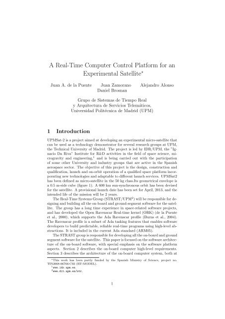
A <strong>Real</strong>-<strong>Time</strong> <strong>Computer</strong> <strong>Control</strong> <strong>Plat<strong>for</strong>m</strong> <strong>for</strong> <strong>an</strong><strong>Experimental</strong> Satellite ∗Ju<strong>an</strong> A. de la Puente Ju<strong>an</strong> Zamor<strong>an</strong>o Alej<strong>an</strong>dro AlonsoD<strong>an</strong>iel Brosn<strong>an</strong>Grupo de Sistemas de Tiempo <strong>Real</strong>y Arquitectura de Servicios Telemáticos,Universidad Politécnica de Madrid (UPM)1 IntroductionUPMSat-2 is a project aimed at developing <strong>an</strong> experimental micro-satellite thatc<strong>an</strong> be used as a technology demonstrator <strong>for</strong> several research groups at UPM,the Technical University of Madrid. The project is led by IDR/UPM, the ”IgnacioDa Riva” Institute <strong>for</strong> R&D activities in the field of space science, microgravity<strong>an</strong>d engineering, 1 <strong>an</strong>d is being carried out with the participationof some other University <strong>an</strong>d industry groups that are active in the Sp<strong>an</strong>ishaerospace sector. The objective of this project is the design, construction <strong>an</strong>dqualification, launch <strong>an</strong>d on-orbit operation of a qualified space plat<strong>for</strong>m incorporatingnew technologies <strong>an</strong>d adaptable to different launch services. UPMSat2has been defined as micro-satellite in the 50 kg class.Its geometrical envelope isa 0.5 m-side cube (figure 1). A 600 km sun-synchronous orbit has been devised<strong>for</strong> the satellite. A provisional launch date has been set <strong>for</strong> April, 2013, <strong>an</strong>d theintended life of the mission will be 2 years.The <strong>Real</strong>-<strong>Time</strong> Systems Group (STRAST/UPM 2 ) will be responsible <strong>for</strong> designing<strong>an</strong>d building all the on-board <strong>an</strong>d ground-segment software <strong>for</strong> the satellite.The group has a long time experience in space-related software projects,<strong>an</strong>d has developed the Open Ravenscar <strong>Real</strong>-time kernel (ORK) (de la Puenteet al., 2000), which supports the Ada Ravenscar profile (Burns et al., 2004).The Ravenscar profile is a subset of Ada tasking features that enables softwaredevelopers to build predictable, reliable real-time programs using high-level abstractions.It is included in the current Ada st<strong>an</strong>dard (ARM05).The STRAST group is responsible <strong>for</strong> developing all the on-board <strong>an</strong>d groundsegment software <strong>for</strong> the satellite. This paper is focused on the software architectureof the on-board software, with special emphasis on the software plat<strong>for</strong>maspects. Section 2 describes the on-board computer high-level requirements.Section 3 describes the architecture of the on-board computer system, both at∗ This work has been partly funded by the Sp<strong>an</strong>ish Ministry of Science, project no.TIN2008-06766-C03 (RT-MODEL).1 www.idr.upm.es.2 www.dit.upm.es/str.1
Figure 1: UPMSat2 external view.the hardware <strong>an</strong>d software levels. Section 4 summarizes the methodological aspectsof the on-board software development. Finally, some conclusions <strong>an</strong>d asummary of the remaining work to be done are recorded in section 6.2 On-Board <strong>Computer</strong> requirements2.1 On-board computer functionalityAll the computer-related functions on board of the UPMSat2 satellite are executedon a single computer plat<strong>for</strong>m, called the On-Board <strong>Computer</strong> (OBC).Its main functions are:Attitude determination <strong>an</strong>d control (ADCS). The attitude of the satellite(i.e. its orientation with respect to the Earth surface) is computed fromthe signals provided by a set of three sensors that measure the intensity ofthe Earth magnetic field on the plat<strong>for</strong>m reference axes (magnetometers).The attitude is controlled most of the time by me<strong>an</strong>s of a passive mech<strong>an</strong>ism,consisting on three sets of perm<strong>an</strong>ent magnets that tend to alignwith the Earth magnetic field. When this is not enough, a set of threemagnetic coils (magneto-torquers) are used as actuators in order to adjustthe attitude to the required <strong>an</strong>gle values.Telemetry <strong>an</strong>d telecomm<strong>an</strong>d m<strong>an</strong>agement (TMTC). The satellite communicateswith the Earth station by me<strong>an</strong>s of two radio links. Telemetrydata (i.e. in<strong>for</strong>mation sent by the satellite to ground) are coded <strong>an</strong>d packagedby the OBC software according to st<strong>an</strong>dard protocols, <strong>an</strong>d sent to thecommunications hardware (TMC) in order to enable the ground operatorsto monitor the operation of the satellite <strong>an</strong>d its orbital parameters.Telecomm<strong>an</strong>ds are produced by the ground equipment <strong>an</strong>d sent by radioto the satellite. Upon reception by the communications hardware, theyare <strong>for</strong>warded to the OBC <strong>for</strong> decoding <strong>an</strong>d execution.<strong>Plat<strong>for</strong>m</strong> monitoring <strong>an</strong>d control. This function includes periodic operational<strong>an</strong>d navigational data measurements (e.g. temperatures <strong>an</strong>d voltagesat various points, orbit <strong>an</strong>d attitude parameters), which are sent to2
TMC!sensors!- magnetometers!SW system!ADCS!TC!TM!actuators!magneto-torquers!plat<strong>for</strong>m!monitoring!payloadmgt!sensors!- temperature!- voltage!- intensity!OBC!payload!Figure 2: OBC context diagram.the ground station by telemetry. Monitoring functions also include detectingsome possible incorrect situations <strong>an</strong>d signalling them to ground.Basic plat<strong>for</strong>m control functions (e.g. power supply <strong>an</strong>d temperature) aremostly carried out directly in hardware. The computer functionality consistson setting references <strong>an</strong>d ch<strong>an</strong>ging operation modes when necessary(e.g. low battery voltage).Fault detection, isolation, <strong>an</strong>d recovery (FDIR). One import<strong>an</strong>t functionis to detect <strong>an</strong>d recover from faults of the computer system itself. The approachto FDIR in the project is mostly based on constructive mech<strong>an</strong>isms,e.g. decoupling of software modules, software cheeks <strong>an</strong>d redund<strong>an</strong>cy.Payload data m<strong>an</strong>agement. The payload is the part of the satellite thatcarries out the mission objectives. Possible payloads <strong>for</strong> the UPMSat2mission include <strong>an</strong> Earth observation system <strong>an</strong>d a marine emergencysurveill<strong>an</strong>ce system.Figure 2 shows a context diagram of the system including its main functionality.2.2 Software requirementsBased on the required functionality, a software system specification document(SSS) has been produced, according to the st<strong>an</strong>dards commonly used in theEurope<strong>an</strong> space industry (ECSS40). The document also includes some nonfunctionalrequirements, including temporal requirements <strong>for</strong> some functions,3
<strong>an</strong>d the requirement to use Ada <strong>an</strong>d open source software to the largest possibleextent.3 <strong>Computer</strong> system architectureThe hardware architecture is based on a LEON3 computer 3 implemented on <strong>an</strong>FPGA, with a clock frequency of 266 MHz. The computer board includes 1 GBof SDRAM, a 1 GB solid state disk, <strong>an</strong>d a number of <strong>an</strong>alog <strong>an</strong>d digital input<strong>an</strong>d output lines.The software architecture is based on the functional components of the system,as depicted on figure 3.sensors!MT!ADCS!plat<strong>for</strong>m!monitoring!TMTC!TMC!MM!OBC!payload!m<strong>an</strong>ager!Figure 3: UPMSat2 software architecture.4 Software development methodology4.1 Model-driven software engineeringFollowing previous experience in the ASSERT 4 <strong>an</strong>d CHESS 5 projects, a modeldrivenengineering approach (Schmidt, 2006; Zamor<strong>an</strong>o <strong>an</strong>d de la Puente, 2010)will be used to develop the on-board software system. Accordingly, the system isfirst described as a high-level plat<strong>for</strong>m-independent model (PIM), which is latertr<strong>an</strong>s<strong>for</strong>med to a plat<strong>for</strong>m-specific model (PSM), including all implementation3 See www.gaisler.com.4 Automated proof-based System <strong>an</strong>d Software Engineering <strong>for</strong> <strong>Real</strong>-<strong>Time</strong> systems. FP7IST IP004033. http://www.assert-project.net5 Composition with Guar<strong>an</strong>tees <strong>for</strong> High-integrity Embedded Software Components Assembly.Artemis JU gr<strong>an</strong>t no. 216882. www.chess.project.ning.com.4
Modelling phase!PIM!PSM!Functionalview"Interfaceview"Deploymentview"Model tr<strong>an</strong>s<strong>for</strong>mation!Concurrencyview"Feasibility <strong>an</strong>alysis!Code generation!Sourcecode"Figure 4: Software development process.details. The system is implemented by automatically generating code from thePSM. Figure 4 shows the main elements of the development process.An import<strong>an</strong>t aspect of such a process is the emphasis on separation ofconcerns. The functional aspects of a system are modelled first, as a set ofcomponents connected by functional interfaces. Non-functional aspects, such astiming properties, are specified as <strong>an</strong>notations of the corresponding operations.Concurrency <strong>an</strong>d real-time behaviour is added at the PSM level, which implementsthe PIM by embedding functional behaviour in containers that exhibitpre-determined properties. Examples are periodic <strong>an</strong>d sporadic tasks, <strong>an</strong>d protected<strong>an</strong>d unprotected passive data objects. A key aspect of the PSM is thatAda source c<strong>an</strong> be generated <strong>for</strong> all kinds of containers (see e.g. Pulido et al.,2007; P<strong>an</strong>unzio <strong>an</strong>d Vard<strong>an</strong>ega, 2011). Another import<strong>an</strong>t point is the availabilityof <strong>an</strong> execution environment that c<strong>an</strong> guar<strong>an</strong>tee that the behaviour exhibitedby the PIM model is really implemented at the plat<strong>for</strong>m level. GNAT/ORK+is <strong>an</strong> example of such <strong>an</strong> execution environment (de la Puente et al., 2008).5 Functional model of the UPMSat2 ADCSThe above ideas have been applied to the development of the attitude determination<strong>an</strong>d control subsystem of the satellite. In order to keep up with thegeneral practice of control engineers, the attitude dynamics <strong>an</strong>d the controls systemhave been modelled using Simulink, 6 as part of the plat<strong>for</strong>m-independentmodel. This high-level model has been used to develop the ADCS code bycarrying out the following steps:6 www.mathworks.com/products/simulink.5
• C sequential code <strong>for</strong> the control algorithm has been automatically generatedfrom the dynamic model using the appropriate Simulink toolkit.• Sequential code is embedded into a cyclic container at the PSM level,using TASTE tools. 7• Final code <strong>for</strong> the full subsystem is generated from the PSM, again usingTASTE tools.• The code is uploaded to the computer board <strong>for</strong> testing. The Simulinkhardware-in-the loop facilities c<strong>an</strong> be used to test the subsystem <strong>an</strong>d validateits operation against a dynamic model of the satellite attitude.6 ConclusionThe UPMSat2 project is <strong>an</strong> excellent occasion <strong>for</strong> our group to apply recentresearch on real-time software engineering to a real space mission. Althoughthe scope <strong>an</strong>d size of <strong>an</strong> academic system is limited, it is still a real developmentwhich will give us the opportunity to show that the ORK+ technology <strong>an</strong>dmodern software engineering methods c<strong>an</strong> be successfully applied in such adem<strong>an</strong>ding kind of applications.We expect to devote the next months until the launch date to completingthe development of the software, <strong>an</strong>d to carry out all the necessary verification<strong>an</strong>d validation activities that will ensure that the software is correct in its final<strong>for</strong>m.AcknowledgmentsThe authors wish to acknowledge the collaboration of the rest of the UPMSat2team, especially Eduardo Ser<strong>an</strong>tes, M<strong>an</strong>uel Rodríguez (RETEMSA), <strong>an</strong>d ÁngelS<strong>an</strong>z, Gustavo Alonso, Ali Rav<strong>an</strong>bakhsh, <strong>an</strong>d Assal Farrahi (IDR/UPM).ReferencesARM05. ISO/IEC 8652:1995(E)/TC1(2000)/AMD1(2007): In<strong>for</strong>mation Technology— Programming L<strong>an</strong>guages — Ada.Al<strong>an</strong> Burns, Bri<strong>an</strong> Dobbing, <strong>an</strong>d Tullio Vard<strong>an</strong>ega. Guide <strong>for</strong> the use of theAda Ravenscar profile in high integrity systems. Ada Letters, XXIV:1–74,June 2004. ISSN 1094-3641. doi: http://doi.acm.org/10.1145/997119.997120.URL http://doi.acm.org/10.1145/997119.997120.Ju<strong>an</strong> A. de la Puente, José F. Ruiz, <strong>an</strong>d Ju<strong>an</strong> Zamor<strong>an</strong>o. An open Ravenscarreal-time kernel <strong>for</strong> GNAT. In Hubert B. Keller <strong>an</strong>d Erhard Plödereder,editors, Reliable Software Technologies — Ada-Europe 2000, number 1845 inLNCS, pages 5–15. Springer-Verlag, 2000.7 Downloadable from www.assert-project.net/-TASTE-.6
Ju<strong>an</strong> A. de la Puente, Ju<strong>an</strong> Zamor<strong>an</strong>o, José A. Pulido, <strong>an</strong>d S<strong>an</strong>tiago Urueña.The ASSERT Virtual Machine: A predictable plat<strong>for</strong>m <strong>for</strong> real-time systems.In Myung Jin Chung <strong>an</strong>d Pradeep Misra, editors, Proceedings of the 17thIFAC World Congress. IFAC-PapersOnLine, 2008.ECSS40. ECSS-E-ST-40C Space engineering — Software. Europe<strong>an</strong> Cooperation<strong>for</strong> Space St<strong>an</strong>dardization, March 2009. Available from ESA.Marco P<strong>an</strong>unzio <strong>an</strong>d Tullio Vard<strong>an</strong>ega. Charting the evolution of the AdaRavenscar code archetypes. In Proceedings of the 15th International <strong>Real</strong>-<strong>Time</strong> Ada Workshop, 2011. to appear on ACM SIGAda Ada Letters.José Pulido, Ju<strong>an</strong> A. de la Puente, Matteo Bordin, Tullio Vard<strong>an</strong>ega, <strong>an</strong>dJérôme Hugues. Ada 2005 code patterns <strong>for</strong> metamodel-based code generation.Ada Letters, XXVII(2):53–58, August 2007. Proceedings of the 13thInternational Ada <strong>Real</strong>-<strong>Time</strong> Workshop (IRTAW13).Douglas C. Schmidt. Model-driven engineering. IEEE <strong>Computer</strong>, 39(2), 2006.Ju<strong>an</strong> Zamor<strong>an</strong>o <strong>an</strong>d Ju<strong>an</strong> A. de la Puente. Design <strong>an</strong>d implementation of realtimedistributed systems with the assert virtual machine. In Emerging Technologies<strong>an</strong>d Factory Automation (ETFA), 2010 IEEE Conference on, pages1 –7, sept. 2010.7