B060-3 - Denver Winair Co.
B060-3 - Denver Winair Co.
B060-3 - Denver Winair Co.

Create successful ePaper yourself
Turn your PDF publications into a flip-book with our unique Google optimized e-Paper software.
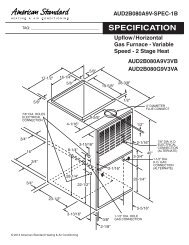
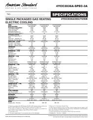
AUD2<strong>B060</strong>A9V-SPEC-1B<br />
TAG: _________________________________<br />
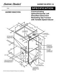
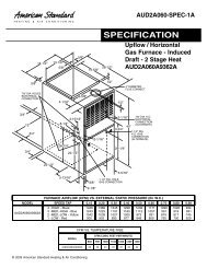
SPECIFICATION<br />
Upflow / Horizontal<br />
Gas Furnace - Variable<br />
Speed - 2 Stage Heat<br />
5/8"<br />
AUD2<strong>B060</strong>A9V3VB<br />
AUD2<strong>B060</strong>G9V3VA<br />
17-1/2"<br />
16-1/4"<br />
5/8"<br />
19-5/8"<br />
28-3/8"<br />
5/8"<br />
1/2"<br />
4" DIAMETER<br />
FLUE CONNECT<br />
7/8" DIA. HOLES<br />
ELECTRICAL<br />
CONNECTION<br />
4-1/16"<br />
9-5/8"<br />
1/2"<br />
3/4"<br />
16"<br />
3/4"<br />
8-1/4"<br />
3-15/16"<br />
2-1/16"<br />
2-1/16"<br />
3-3/4"<br />
40"<br />
7/8" DIA. K.O.<br />
ELECTRICAL<br />
CONNECTION<br />
(ALTERNATE)<br />
1-1/2" DIA.<br />
K.O. GAS<br />
CONNECTION<br />
(ALTERNATE)<br />
3/4"<br />
28-1/4"<br />
22-1/2"<br />
28-1/4"<br />
23-1/2"<br />
3-13/16"<br />
3/8"<br />
2-1/8"<br />
1-1/2" DIA. HOLE<br />
GAS CONNECTION<br />
5-5/16"<br />
© 2013 American Standard Heating & Air <strong>Co</strong>nditioning
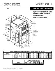
*UD2<strong>B060</strong>A9V3VB, *UD2<strong>B060</strong>G9V3VA FURNACE HEATING AIRFLOW (CFM) AND POWER (WATTS) VS. EXTERNAL STATIC<br />
PRESSURE WITH FILTER<br />
AIRFLOW<br />
SETTING<br />
DIP SWITCH SETTING<br />
EXTERNAL STATIC PRESSURE<br />
SW7 SW8 0.1 0.3 0.5 0.7 0.9<br />
LOW ON ON<br />
CFM<br />
TEMP. RISE<br />
WATTS<br />
589<br />
49<br />
65<br />
604<br />
48<br />
95<br />
619<br />
47<br />
125<br />
604<br />
48<br />
160<br />
607<br />
48<br />
200<br />
HEATING<br />
1ST<br />
STAGE<br />
MEDIUM ** ON OFF<br />
CFM<br />
TEMP. RISE<br />
WATTS<br />
663<br />
44<br />
75<br />
694<br />
42<br />
120<br />
684<br />
42<br />
145<br />
681<br />
42<br />
185<br />
686<br />
42<br />
220<br />
HIGH OFF OFF<br />
CFM<br />
TEMP. RISE<br />
WATTS<br />
775<br />
37<br />
105<br />
781<br />
37<br />
145<br />
776<br />
37<br />
180<br />
805<br />
36<br />
230<br />
811<br />
36<br />
270<br />
LOW ON ON<br />
CFM<br />
TEMP. RISE<br />
WATTS<br />
813<br />
55<br />
110<br />
818<br />
54<br />
150<br />
818<br />
54<br />
185<br />
837<br />
53<br />
240<br />
842<br />
53<br />
280<br />
HEATING<br />
2ND<br />
STAGE<br />
MEDIUM ** ON OFF<br />
CFM<br />
TEMP. RISE<br />
WATTS<br />
907<br />
49<br />
140<br />
919<br />
48<br />
200<br />
942<br />
47<br />
240<br />
958<br />
46<br />
300<br />
959<br />
46<br />
330<br />
HIGH OFF OFF<br />
CFM<br />
TEMP. RISE<br />
WATTS<br />
1038<br />
43<br />
190<br />
1066<br />
42<br />
260<br />
1086<br />
41<br />
325<br />
1089<br />
41<br />
365<br />
1079<br />
41<br />
415<br />
*UD2<strong>B060</strong>A9V3VB, *UD2<strong>B060</strong>G9V3VA FURNACE COOLING AIRFLOW (CFM) AND POWER (WATTS) VS. EXTERNAL STATIC<br />
PRESSURE WITH FILTER<br />
OUTDOOR<br />
UNIT SIZE<br />
(TONS)<br />
AIRFLOW<br />
SETTING<br />
LOW<br />
(350 CFM/ TON)<br />
DIP SWITCH SETTING<br />
EXTERNAL STATIC PRESSURE<br />
SW1 SW2 SW3 SW4 0.1 0.3 0.5 0.7 0.9<br />
ON ON OFF ON<br />
CFM<br />
WATTS<br />
499<br />
50<br />
537<br />
80<br />
520<br />
110<br />
520<br />
145<br />
500<br />
175<br />
1.5<br />
NORMAL<br />
(400 CFM/ TON)<br />
ON ON OFF OFF<br />
CFM<br />
WATTS<br />
605<br />
60<br />
610<br />
80<br />
610<br />
120<br />
597<br />
155<br />
593<br />
180<br />
HIGH<br />
(450 CFM/ TON)<br />
ON ON ON OFF<br />
CFM<br />
WATTS<br />
649<br />
75<br />
681<br />
110<br />
665<br />
145<br />
665<br />
180<br />
672<br />
220<br />
LOW<br />
(350 CFM/ TON)<br />
OFF ON OFF ON<br />
CFM<br />
WATTS<br />
680<br />
80<br />
722<br />
125<br />
680<br />
150<br />
696<br />
190<br />
696<br />
225<br />
2<br />
NORMAL<br />
(400 CFM/ TON)<br />
OFF ON OFF OFF<br />
CFM<br />
WATTS<br />
798<br />
105<br />
804<br />
145<br />
809<br />
170<br />
823<br />
235<br />
818<br />
280<br />
HIGH<br />
(450 CFM/ TON)<br />
OFF ON ON OFF<br />
CFM<br />
WATTS<br />
884<br />
145<br />
896<br />
180<br />
924<br />
240<br />
931<br />
280<br />
931<br />
330<br />
LOW<br />
(350 CFM/ TON)<br />
ON OFF OFF ON<br />
CFM<br />
WATTS<br />
858<br />
125<br />
863<br />
175<br />
882<br />
220<br />
894<br />
275<br />
895<br />
320<br />
2.5<br />
NORMAL<br />
(400 CFM/ TON)<br />
ON OFF OFF OFF<br />
CFM<br />
WATTS<br />
984<br />
170<br />
1017<br />
225<br />
1038<br />
295<br />
1017<br />
330<br />
1017<br />
375<br />
HIGH<br />
(450 CFM/ TON)<br />
ON OFF ON OFF<br />
CFM<br />
WATTS<br />
1125<br />
245<br />
1138<br />
315<br />
1150<br />
370<br />
1161<br />
435<br />
1161<br />
475<br />
LOW<br />
(350 CFM/ TON)<br />
OFF OFF OFF ON<br />
CFM<br />
WATTS<br />
1035<br />
205<br />
1056<br />
265<br />
1076<br />
330<br />
1076<br />
370<br />
1076<br />
430<br />
3 **<br />
NORMAL **<br />
(400 CFM/ TON)<br />
OFF OFF OFF OFF<br />
CFM<br />
WATTS<br />
1208<br />
300<br />
1247<br />
360<br />
1268<br />
440<br />
1278<br />
485<br />
1200<br />
490<br />
HIGH<br />
(450 CFM/ TON)<br />
OFF OFF ON OFF<br />
CFM<br />
WATTS<br />
NOTES:<br />
1. *FIRST LETTER MAY BE "A" OR "T"<br />
2. **FACTORY SETTING.<br />
3. CONTINUOUS FAN SETTING: HEATING OR COOLING AIRFLOW IS APPROXIMATELY 50% OF SELECTED COOLING VALUE.<br />
4. LOW 350 CFM/TON IS RECOMMENDED FOR VARIABLE SPEED APPLICATION FOR COMFORT & HUMID CLIMATE SETTING:<br />
NORMAL IS 400 CFM/TON: HIGH 450 CFM/TON IS FOR DRY CLIMATE SETTING.<br />
1380<br />
440<br />
1410<br />
500<br />
1402<br />
550<br />
1350<br />
550<br />
1235<br />
525
INDOOR BLOWER TIMING<br />
Heating: The ECM Fan <strong>Co</strong>ntrol controls the variable speed<br />
indoor blower. The blower "on" time is fixed at 45 seconds after<br />
ignition. The FAN-OFF period is field selectable by dip switches<br />
#2 and #3 on the Integrated Furnace <strong>Co</strong>ntrol at 60, 100, 140,<br />
or 180 seconds. The factory setting is 100 seconds, (See unit<br />
wiring diagram).<br />
<strong>Co</strong>oling: The fan delay-off period is set by dip switches on the<br />
ECM Fan <strong>Co</strong>ntrol board connected to the Integrated Furnace<br />
<strong>Co</strong>ntrol. The options for cooling delay off is field selectable by<br />
dip switches #5 and #6. However, dip switch #1 on the Integrated<br />
Furnace <strong>Co</strong>ntrol must be set to "ON" for cooling mode to<br />
function properly.<br />
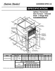
The following table and graph explain the delay-off settings:<br />
** - This selection provides a ramping up and ramping down<br />
of the blower speed to provide improved comfort, quietness, and<br />
potential energy savings. The graph below shows the ramping<br />
process.<br />
COOLING OFF - DELAY OPTIONS<br />
NOMINAL-<br />
SWITCH SETTINGS SELECTION<br />
AIRFLOW<br />
5 - OFF 6 - OFF NONE SAME<br />
5 - ON 6 - OFF 1.5 MINUTES 100% *<br />
5 - OFF 6 - ON 3 MINUTES 50%<br />
5 - ON 6 - ON ** 50 - 100%<br />
* - This setting is equivalent to BAY24X045 relay benefit<br />
** - This selection provides ENHANCED MODE, which<br />
is a ramping up and ramping down of the blower speed to<br />
provide improved comfort, quietness, and potential energy<br />
savings. See Wiring Diagram notes on the unit or in the Service<br />
Facts for complete wiring setup for ENHANCED MODE.<br />
The graph which follows, shows the ramping process.<br />
100% if necessary<br />
80%<br />
50%<br />
Dehumidify<br />
50%<br />
Fast <strong>Co</strong>il <strong>Co</strong>oling<br />
Efficiency<br />
OFF<br />
OFF<br />
1<br />
minute<br />
7.5<br />
minutes<br />
3<br />
minutes<br />
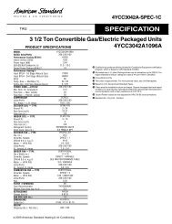
General Data 1<br />
TYPE<br />
RATINGS 2<br />
1st Stage Input BTUH<br />
1st Stage Capacity BTUH (ICS) 3<br />
2nd Stage Input BTUH<br />
2nd Stage Capacity BTUH (ICS) 3<br />
Temp. rise (Min.-Max.) °F.<br />
BLOWER DRIVE<br />
Diameter-Width (In.)<br />
No. Used<br />
Speeds (No.)<br />
CFM vs. in. w.g.<br />
Motor HP<br />
R.P.M.<br />
Volts/Ph/Hz<br />
FLA<br />
COMBUSTION FAN - Type<br />
Drive - No. Speeds<br />
Motor HP - RPM<br />
Volts/Ph/Hz<br />
F.L. Amps<br />
FILTER — Furnished?<br />
Type Recommended<br />
Hi Vel. (No.-Size-Thk.) Shipped<br />
Upflow / Horizontal<br />
39,000<br />
31,200<br />
60,000<br />
48,000<br />
30 - 60<br />
DIRECT<br />
10 x 7<br />
1<br />
VARIABLE SPEED<br />
See Fan Performance<br />
1/2<br />
VARIABLE<br />
115/1/60<br />
7.7<br />
Centrifugal<br />
Direct - 2<br />
1/100 - 2543 / 1727<br />
115/1/60<br />
0.70 / 0.40<br />
Yes<br />
High Velocity<br />
1 - 17 x 25 - 1in.<br />
VENT COLLAR — Size (in.)<br />
HEAT EXCHANGER<br />
Type-Fired<br />
-Unfired<br />
Gauge (Fired)<br />
ORIFICES — Main<br />
Nat.Gas. Qty. — Drill Size<br />
L.P. Gas Qty. — Drill Size<br />
GAS VALVE<br />
PILOT SAFETY DEVICE<br />
Type<br />
BURNERS — Type<br />
Number<br />
POWER CONN. — V/Ph/Hz 4<br />
Ampacity (In Amps)<br />
Max. Overcurrent Protection (amps)<br />
PIPE CONN. SIZE (IN.)<br />
DIMENSIONS<br />
Crated (In.)<br />
Uncrated (In.)<br />
WEIGHT<br />
Shipping (Lbs.) / Net (Lbs)<br />
4 Round<br />
Alum. Steel<br />
20<br />
3 — 45<br />
3 — 56<br />
Redundant - Two Stage<br />
Hot Surface Ignition<br />
Multiport Inshot<br />
3<br />
115/1/60<br />
10.5<br />
15<br />
1/2<br />
H x W x D<br />
41- 3/4 x 19-1/2 x 30-1/2<br />
40 x 17-1/2 x 28-1/2<br />
136 / 126<br />
1 Central Furnace heating designs are certified to ANSI Z21.47 / CSA 2.3<br />
2 Ratings shown are for elevations up to 2000 feet. For elevations above 2000 feet; Ratings should be reduced at the rate of 4% for each 1000 feet above sea level.<br />
3 Based on U.S. Government Standard Tests.<br />
4 The above wiring specifications are in accordance with National Electrical <strong>Co</strong>de; however, installations must comply with local codes.
Mechanical Specifications<br />
NATURAL GAS MODELS — Central heating<br />
furnace designs are certified to ANSI Z21.47<br />
/ CSA 2.3 for both natural and L.P. gas. Limit<br />
setting and rating data were established and<br />
approved under standard rating conditions<br />
using American National Standards Institute<br />
standards.<br />
SAFE OPERATION — The Integrated System<br />
<strong>Co</strong>ntrol has solid state devices, which<br />
continuously monitor for presence of flame,<br />
when the system is in the heating mode of<br />
operation. Dual solenoid combination gas<br />
valve and regulator provide extra safety.<br />
QUICK HEATING— Durable, cycle tested,<br />
heavy gauge aluminized steel heat exchanger<br />
quickly transfers heat to provide<br />
warm conditioned air to the structure. Low<br />
energy power vent blower, to increase efficiency<br />
and provide discharge of gas fumes<br />
to the outside, allows common venting with<br />
hot water heater.<br />
BURNERS — Multi-port, in-shot burners will<br />
give years of quiet and efficient service. All<br />
models can be converted to L.P. gas without<br />
changing burners.<br />
INTEGRATED SYSTEM CONTROL— Exclusively<br />
designed operational program provides<br />
total control of furnace limit sensors, blowers,<br />
gas valve, flame control and includes self<br />
diagnostics for ease of service.<br />
AIR DELIVERY — The variable speed, directdrive<br />
blower motor, with sufficient airflow<br />
range for most heating and cooling requirements,<br />
will switch from heating to cooling<br />
speeds on demand from room thermostat.<br />
The blower door safety switch will prevent or<br />
terminate furnace operation when the blower<br />
door is removed. (Fan relay and 35VA control<br />
transformer is standard).<br />
STYLING — Heavy gauge steel and "wraparound"<br />
cabinet construction is used in<br />
the cabinet with baked-on enamel finish for<br />
strength and beauty. The heat exchanger<br />
section of the cabinet is completely lined with<br />
foil-faced fiberglass insulation. This results<br />
in quiet and efficient operation due to the<br />
excellent acoustical and insulating qualities<br />
of fiberglass.<br />
FEATURES AND GENERAL OPERATION<br />
— These High Efficiency Gas Furnaces<br />
employ a Hot Surface Ignition system, which<br />
eliminates the waste of a constantly burning<br />
pilot. The integrated system control lights<br />
the main burners upon a demand for heat<br />
from the room thermostat. <strong>Co</strong>mplete front<br />
service access.<br />
a. Low energy power venter.<br />
b. Vent proving differential switch.<br />
Since American Standard Heating & Air <strong>Co</strong>nditioning has<br />
a policy of continuous product and product data improvement,<br />
it reserves the right to change specifications and<br />
design without notice.<br />
Technical Literature - Printed in U.S.A.<br />
American Standard<br />
Heating & Air <strong>Co</strong>nditioning<br />
6200 Troup Highway<br />
Tyler, TX 75707<br />
www.americanstandardair.com<br />
Library<br />
Product Section<br />
Product<br />
Model<br />
Literature Type<br />
Sequence<br />
Date<br />
File No.<br />
Supersedes<br />
-<br />
Furnaces<br />
Furnace<br />
AUD2-9V<br />
Submittal<br />
-<br />
08/13<br />
AUD2<strong>B060</strong>A9V-SPEC-1B<br />
AUD2<strong>B060</strong>A9V-SPEC-1A