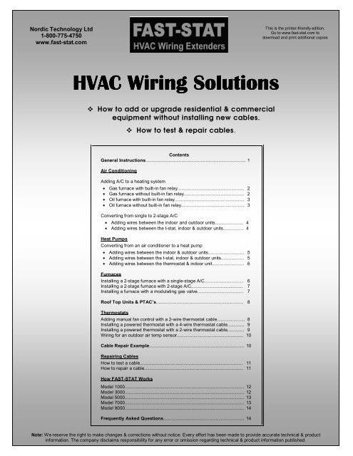
Fast Stat Wiring Solutions
Fast Stat Wiring Solutions
Fast Stat Wiring Solutions
Create successful ePaper yourself
Turn your PDF publications into a flip-book with our unique Google optimized e-Paper software.
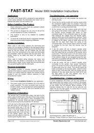
General InstructionsWhen used at a thermostat, the Sender wires are connectedto the thermostat and thermostat cable. The Sender isinserted into the wall space behind the thermostat. Thethermostat is then mounted to the wall. as usual.The Receiver is installed at the indoor or outdoor unit. It isthen connected to the thermostat or condenser cable and thecontrol board.Page 1
Air Conditioning – Gas furnace with built-in fan relayProject: Adding a single-stage air conditioner to aheating system with a 2-wire thermostat cable.Problem: Not enough wires between the thermostatand indoor unit.Solution: Use a Model 3000 to make a 2-wirethermostat cable into a 4-wire cable.ThermostatGYRWGreenYellowRedWhiteSenderPurpleRedThermostatCableReceiverFAST-STAT3000Details: Install the Sender into the wall space behindthe thermostat. Connect 2 wires from the Sender tothe thermostat cable and the other 4 wires to thethermostat. Install the Receiver in the indoor unitnear the control board. Connect 2 wires from theReceiver to the thermostat cable, 2 wires totransformer power (R & C) and the remaining 3wires to the fan (G), condenser (Y) and heat (W)connections.RedRedPurpleYellowBlackWhiteGreenRYCWGYCCompressorTransformerHeatFanOutdoor UnitL1L2 (N)Indoor UnitAir Conditioning – Gas furnace without built-in fan relayProject: Adding a single-stage air conditioner to aheating system with a 2-wire cable.Problem: Not enough wires between the thermostatand indoor unit.Solution: Use a Model 3000 to make a 2-wirethermostat cable into a 4-wire cable. A fan centerand a relay are required for this installation.ThermostatGYRWGreenYellowRedWhiteSenderPurpleRedThermostatCableReceiverFAST-STAT3000Details: Install the fan center according to themanufacturer’s instructions. Install the Sender intothe wall space behind the thermostat. Connect 2wires from the Sender to the thermostat cable andthe other 4 wires to the thermostat. Install theReceiver in the indoor unit. Connect 2 wires fromthe Receiver to the thermostat cable, 2 wires to thefan center transformer power (R & C) and 2 wires tothe fan center fan (G) & condenser (Y) connections.The Receiver white wire is connected to a relay. Therelay is used to control heat (W). The relay is used toisolate the two transformers from each other. The120 volt wiring for the fan is not shown – see the fancenter instructions.YCRRedYYellowCRedBlackGPurpleGreenRWhiteRelayWCompressorTransformerFanTransformerHeatOutdoor UnitL1 L2 (N) Fan CenterL1L2 (N)Indoor UnitPage 2
Air Conditioning – Oil furnace with built-in fan relayProject: Adding a single-stage air conditioner to aheating system with a 2-wire cable.Problem: Not enough wires between the thermostatand indoor unit.Solution: Use a Model 3000 to make a 2-wirethermostat cable into a 4-wire cable. A relay may berequired for this installation.ThermostatGYRWGreenYellowRedWhiteSenderPurpleRedThermostatCableReceiverFAST-STAT3000Details: Install the Sender into the wall spacebehind the thermostat. Connect 2 wires from theSender to the thermostat cable and the other 4 wiresto the thermostat. Install the Receiver in the indoorunit near the control board. Connect 2 wires fromthe Receiver to the thermostat cable, 2 wires totransformer power (R & C) and 2 wires to the fan(G), condenser (Y) connections. Install a relay andconnect the Receiver white wire to it. The relay isused to complete the circuit between the T1 & T2terminals on a call for heat. If the furnace has one“W” terminal instead of 2 – “T” terminals then therelay is not required and the white wire is thendirectly connected to the “W” terminal.Y CCompressorRRedYellowYTransformerRedCPurpleBlackRelayTHeatTWhiteGFanGreenOutdoor UnitL1L2 (N)Indoor UnitAir Conditioning – Oil furnace without built-in fan relayProject: Adding a single-stage air conditioner to aheating system with a 2-wire cable.Problem: Not enough wires between the thermostatand indoor unit.Solution: Use a Model 3000 to make a 2-wirethermostat cable into a 4-wire cable. A fan center anda relay are required for this installation.ThermostatGYRWGreenYellowRedWhiteSenderPurpleRedThermostatCableReceiverFAST-STAT3000Details: Install the fan center according to themanufacturer’s instructions. Install the Sender intothe wall space behind the thermostat. Connect 2wires from the Sender to the thermostat cable and theother 4 wires to the thermostat. Install the Receiverin the indoor unit. Connect 2 wires from the Receiverto the thermostat cable, 2 wires to the fan centertransformer power (R & C) and 2 wires to the fancenter fan (G) & condenser (Y) connections. TheReceiver white wire is connected to a relay. Therelay is used to control heat (W). The 120 volt wiringfor the fan is not shown – see fan center instructions.RRedYYellowCRedBlackGPurpleGreenWhiteRelayTTY CCompressorOutdoor UnitTransformerFanL1 L2 (N) Fan CenterHeatIndoor UnitPage 3
Air Conditioning – Adding wires between the indoor & outdoor units.Project: Replacing a single-stage A/C with a 2-stage A/C.Problem: Not enough wires between the indoor andoutdoor units.Solution: Use a Model 1000 to make a 2-wirethermostat cable into a 4-wire cable.Details: Install the Sender at the furnace / airhandler. Connect the Sender green wire to thefurnace Y2 terminal, the yellow wire to the Y1terminal and the purple wire to the Receiver purplewire using one of the wires in the existingcondenser cable. Use the other condenser cable wireto connect “R” from the indoor unit to the outdoorunit “R” connection. Install the Receiver in theoutdoor unit and connect the green wire to “Y2”,the yellow wire to “Y1”, the black wire to “C”, andthe red wire to “R”. At both the indoor and outdoorunits install a jumper between the “C” connectionsand electrical ground.GreenFAST-STAT1000Y2YellowBlackY1RedCRPurpleGWCY2Y1RExistingCondenserCableThermostatPurpleSenderGreenYellowR Y1 Y2CWGStage 2 Stage 1 Control BoardConnect Commons toelectrical ground.TransformerHeatFanOutdoor UnitL1L2 (N)Indoor UnitAir Conditioning – Adding wires between the t-stat, indoor & outdoor units.Project: Replacing a single-stage A/C with a 2-stageA/C.Problem: Not enough wires between the thermostatand indoor unit and also between the indoor andoutdoor units.Solution: Use 2 - Model 1000’s.ThermostatWGCRY2Y1GreenYellowSenderPurpleThermostatCableDetails: Install the Sender at the thermostat. Connectthe Sender green wire to the Y2 terminal, the yellowwire to the Y1 terminal and the purple wire to theReceiver purple wire using one of the wires in thethermostat cable. Install one receiver at the indoorunit to control the fan speed. Use one of thecondenser cable wires to connect the purple of onereceiver to the purple wire of the other receiver. Usethe other condenser cable wire to connect “R” fromthe indoor unit to the outdoor unit “R” connection.Install the Receiver in the outdoor unit and connectthe green wire to “Y2”, the yellow wire to “Y1”, theblack wire to “C”, and the red wire to “R”. At boththe indoor and outdoor units install a jumper betweenthe “C” connections and electrical ground.ReceiverFAST-STAT1000PurpleBlackRedGreenYellowExistingcondensercableY1 Y2R C G WTransformerFanControlFurnace /Air HandlerHeatControlReceiverFAST-STAT1000PurpleRedBlackYellowGreenY2Y1CRConnect indoor & outdoor unitcommons "C" to electrical ground.Stage 2Stage 1ControlBoardCondenserPage 4
Heat Pumps – Adding wires between the indoor & outdoor units.Project: Replacing an A/C with a single or 2-stage heat pump.Problem: Not enough wires between theindoor unit and the outdoor unit.Solution: Use a Model 9000.Details: Install the Indoor Unit Module at theindoor unit. Connect yellow to Y1, brown toY2, blue to O/B, white to W, & Red to R.Connect one Black to C & the other black toground. Connect the orange wire to theorange wire of the outdoor unit module usingone of the wires in the existing condensercable. Use the other condenser cable wire toconnect “R” from the indoor unit to theoutdoor unit “R” connection. Install theOutdoor Unit Module in the outdoor unit andconnect yellow to Y1, brown to Y2, blue toO/B, white to W, & red to R. Connect oneBlack to C & the other black to ground. If thebuilt-in dual fuel controller is not used, thenleave the grey, green, & purple wires as theyare.FAST-STAT9000Heat PumpModuleReversingValveBlueGreen - Cut for "Fossil Fuel" modeBrownPurple - Cut for "cool active reversing valve"YellowHeat PumpBlackRedOB Y2 Y1 W C RCompressorStage 2CompressorStage 1Heat PumpControl BoardGreyGreyOrangeWhiteRemoteBulbThermostat(optional use)DefrostHeat30 40205010 600ThermostatGY1Y2CWRO/BMount bulb out of directsunlight and in an areafree of snow build up.BlackExistingCondenserCableOrangeFAST-STAT9000Indoor UnitModuleHeat Pumps – adding wiring between the t-stat, indoor & outdoor unitsThermostatProject: Replacing an A/C with a single or 2-stage heat pump.Problem: Not enough wires between thethermostat, indoor unit and the outdoor unit.Solution: Use a Model 7000. A 4-wirethermostat & a 2-wire condenser cable isrequired.CRGWY1Y2O/BW2, H, D, L etc.BlackRedGreenWhiteYellowBrownBlueBlackRedGrayPurpleNote:Extra wires can beused for otherfunctions. Connectdirectly to thermostatand load as indicated.Details: Connect the Sender and install it inthe wall space behind the thermostat. Installthe Furnace/ Air Handler and Heat PumpModules as shown below. Connect oneBlack wire to C & the other black to groundat both modules. For single-stage use join theyellow & brown wires together onto the “Y”connections. If the built-in dual fuelcontroller is not used, then leave the grey,green, & purple wires as they are.FAST-STATHeat PumpModuleGreen - Cut for "Fossil Fuel" modePurple - Cut for "cool active reversing valve"GreyGreyRemote BulbThermostat(optional use)30 40205010 600OrangeSenderExistingCondenserCableExistingThermostatCablePurpleGrayRedBlackOrangeFAST-STATFurance /Air HandlerModuleBlackBlackFor Single-Stage joinyellow & brown wirestogether onto the "Y1"connection at bothmodules.BlueBrownYellowBlackWhiteRedRWHeat ControlTransformerCY1 Y2 GFan ControlFurnace /Air HandlerL1BlueBrownYellowWhiteBlackRedNOB Y2 Y1 W C RBlackRRedWhiteBlackGreenWCGBrownY2ReversingValveStage 2Stage 1DefrostHeatHeat PumpControl BoardTransformerHeat ControlFan ControlHeat PumpL1 N Furnace / Air HandlerPage 5
Heat Pumps – adding wiring between t-stat and indoor unitProject: Replacing an A/C with a single or 2-stageheat pump.Problem: Not enough wires between the thermostatand the indoor unit.Solution: Use a Model 5000.Details: The drawing below is for a “fossil-fuel”connection. The heat pump is shut off when thethermostat W1 and/or W2 is on. Connect theSender and install it in the wall space behind thethermostat. Install the Receiver in the Furnace/ AirHandler and connect as shown below. Forsupplemental heat operation (heat pump staysrunning when W1 and/or W2 is on) a relay wouldneed to added at the Receiver to provide power toY1 when W1 and/or W2 is on. For a single stagefurnace or strip heater, join the white and bluewires together onto the “W” connections.Y2O/BRGYW1W2CThermostatW3,Y2,H,C, etc.RedGreenYellowWhiteBlueBlackSenderFAST-STAT5000RedPurpleNote:Extra wires can be used for otherfunctions. Connect directly tothermostat and load as indicated.ExistingThermostatCablePurpleRedReceiverYellowBlackRedGreenWhiteBlueY1CRGW1 W2Y2OB Y2Y1CRTransformerFanControlHeatStage 1HeatStage 2Heat PumpIndoor UnitFurnaces – 2-stage heat with single-stage coolProject: Installing a 2-stage furnace with a singlestageair conditioner.Problem: Not enough wires between the thermostatand indoor unit.Solution: Use a Model 5000. Requires a minimumof a 2-wire thermostat cable.Details: Install the Sender at the thermostat and theReceiver at the indoor unit. Connect wires as shownbelow. Extra thermostat cable wires can be used forother functions such as Y2 etc.RGYW1W2CThermostatW3,Y2,O/B,H,C, etc.RedGreenYellowWhiteBlueBlackSenderNote:Extra wires can be used for otherfunctions. Connect directly tothermostat and load as indicated.RedPurpleExistingThermostatCableRedPurpleReceiverFAST-STAT5000YellowBlackRedGreenWhiteY C R G W1 W2BlueCompressorControlTransformerFanControlHeatStage 1HeatStage 2Furnace <strong>Wiring</strong>Page 6
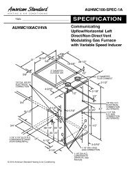
Furnaces – 2-stage heat & coolProject: Installing a 2-stage furnace with a 2-stageair conditioner.Problem: Not enough wires between the thermostatand indoor unit.Solution: Use a Model 5000. Requires a minimumof a 3-wire thermostat cable for this application.Details: Install the Sender at the thermostat and theReceiver at the indoor unit. Connect wires as shownbelow.Y2RGY1W1W2CThermostatRedGreenYellowWhiteBlueBlackSenderRedPurpleExistingThermostatCableRedPurpleReceiverFAST-STAT5000Y2YellowBlackRedGreenWhiteY1 C R G W1 W2BlueY2CompressorControlTransformerFanControlHeatStage 1HeatStage 2Furnace <strong>Wiring</strong>Furnaces – modulating gas valveProject: Installing a furnace with a modulating gasvalve.Problem: Not enough wires between the thermostatand indoor unit.Solution: Use a Model 1000.Details: By combining the Fan “G” andCompressor “Y” together on one wire, a wire ismade available for use to connect the modulatinggas valve connection to the thermostat.GYWW-modCRThermostatGreenYellowSenderRedPurplePurpleThermostatCableReceiver1000FAST-STATYellowBlackGreenYRCWM WGTransformerHeatFanPage 13L1L2 (N)Indoor UnitPage 7
Roof Top Units & PTAC’sProject: Upgrading a RTU or PTAC.Problem: Not enough wires between the thermostatand unit.Solution: The Model to use depends on the numberof additional wires that are required. To add onemore wire use a Model 1000.To add two wires usea Model 3000. To add four wires use a Model 5000.More than one FAST-STAT wiring extender can beused on the same system. For example, with a 4-wire cable a Model 1000 and a Model 3000 couldboth be used if needed.ThermostatGY2RW2Y1W1GreenYellowRedWhiteSenderPurpleRedThermostatCableRedPurpleReceiverFAST-STAT3000Details: Connect the Sender and install it in thewall space behind the thermostat. Install theReceiver in the RTU/PTAC. In the example below,a Model 3000 is used to add 2-stage heating and 2-stage cooling control to a unit using a 4-wire cable.RedRCBlackWhiteGreenW1 W2GY1YellowY2Project: Adding manual fan control with a 2-wirecable.Problem: Not enough wires between the thermostatand indoor unit.Solution: Use a Model 1000.GWRGreenYellowSenderPurpleThermostatCableDetails: Connect the Sender and install it in thewall space behind the thermostat. Install theReceiver in the Furnace/ Air Handler and connect asshown below.ThermostatPurpleReceiver1000FAST-STATRedBlackYellowGreenTransformerL1L2 (N)Heat FanStage 1HeatStage 2UnitCompressorStage 1CompressorStage 2Thermostats – adding manual fan controlRCWGTransformerHeatFanL1L2 (N)Indoor UnitPage 8
Thermostats – installing a powered thermostatProject: Installing a powered thermostat with a 4-wire cable.Problem: Not enough wires between the thermostatand the indoor unit.Solution: Use a Model 1000.Details: By combining the Fan “G” andCompressor “Y” together on one wire, a wire ismade available for use to connect the commonconnection to the thermostat.GYWCRThermostatGreenYellowSenderPurpleRedPurpleThermostatCableReceiver1000FAST-STATProject: Installing a powered thermostat with a 2-wire cable.CWBlackWhiteSenderPurpleProblem: Not enough wires between the thermostatand the indoor unit.RThermostatCableSolution: Use a Common Maker. (This is a specialorder product)ThermostatPurpleReceiverDetails: The Sender of the Common Maker createsa common connection with only a 2-wire cable.Connect as shown below.RedFAST-STATCommonMakerBlackYellowBlackGreenYRCWGTransformerHeatFanL1L2 (N)Indoor UnitThermostats - Installing a powered thermostat with a 2-wire cable.RCWTransformerHeatL1L2 (N)Indoor UnitPage 9
Thermostats – adding an outdoor temperature sensorProject: <strong>Wiring</strong> for an outdoor temperature sensor.Problem: Not enough wires between the thermostatand the indoor unit.Solution: Use a Model 3000. A 4-wire thermostatcable is required.Details: The Model 3000 is used to combine R, G,Y & W together on two wires. This provides twowires that can be used to connect the outdoor airtemperature sensor.ThermostatGYRWSensorGreenYellowRedWhiteSenderPurpleRedThermostatCableRedPurpleReceiverFAST-STAT3000SensorRedYellowBlackWhiteGreenRYCWGYCCompressorTransformerHeatFanOutdoor UnitL1L2 (N)Indoor UnitCable Repair ExampleProject: Repairing a cable with 1 broken wire.Solution: Use a Model 1000.Details: The wire that was used for “Y” has beencut and no longer functions. A Model 1000 is usedto combine G & Y together on 1 wire. The 3-wirecable now operates as a 4-wire cable again.GYWRGreenYellowSenderPurpleThermostatCableThermostatPurpleReceiverRed1000FAST-STATYellowBlackGreenYRCWGTransformerHeatFanL1L2 (N)Indoor UnitPage 10
How To Test a CableStep 1Disconnect the cable from the thermostat and indoor unit terminals.Step 2Make a chart similar to the example. List each wire in order from L to R & topto bottom. The last column is always “Grd” which stands for “Ground”.Step 3At the indoor unit, set meter to ohms and measure from test wire to each otherwire. Using the chart as an example, measure from red to white, red to green,red to black & red to ground. Once a row is completed move down to next row.Record the results in the left side square for each wire. The blacked-out squaresdo not need to be tested. Good wires should read “infinity” when tested thisway. Once completed do step 4.Step 4At one end of the cable join together the red & white wires together. Go to theother end of the cable and measure the ohms. Repeat this for all the wires in therow. When completed, move down to the next row and repeat. Good wires willalways have a 1 to 50 ohms reading. Record the results in right side square foreach wire.NotesIn the chart examples “in” stands for “infinity”. Any reading above 100K ohmscould be considered the same as infinity. The actual ohms measured willdepend on cable length.RedWhiteGreenBlackRed White Green Black GrdExample: Results of a good cableRed White Green Black GrdRed in 8 in 7 in 8 inWhite in 8 in 6 inGreen in 7 inBlackinExample: White is broken (open circuit)Red White Green Black GrdRed in in in 9 in 8 inWhite In in In In InGreen In 8 InBlackinRepairing CablesGeneral Rules1. Wires shorted to ground can only be used for Common “C” connections.Some equipment might not function properly with a grounded common.2. Any wires shorted together can still be used, however they must be used asone single wire. Reliability might be an issue if the wire breaks later on. If a nailor screw has gone through the cable and has shorted two or more wires together,there is no way to determine to what degree the copper wires have beendamaged. Any subsequent movement of the cable might cause the wire to breakwhere the nail/screw is.3. Wires that test as broken or open cannot be used.Problem: Two wires are shorted together on a 4-wire cable.Solution: If two wires out of a 4-wire cable are shorted together then the cableis used as if it is a 3-wire cable. To repair this cable a Model 1000 could be usedto provide 4-wire control again.Example: Green is shorted to groundRed White Green Black GrdRed in 8 in 7 in 8 inWhite in 8 in 6 InGreen in 7 5BlackInExample: Black & Red are shorted togetherRed White Green Black GrdRed in 7 in 7 8 8 inWhite in 8 in 6 inGreen in 7 inBlackinProblem: Three wires are shorted together on a 4-wire cable.Solution: This cable is used as if it was a 2-wire. If it is a thermostat cable then a Model 3000 could be used toprovide 4-wire control for most applications. If it is a condenser cable then a Model 1000 or 3000 could be used.Problem: All the wires are shorted together on a cable.Solution: If it is a thermostat cable then the cable would need to be replaced. If it is a condenser cable a Model1000, 3000 or 9000 could be used depending if the outdoor unit was an air conditioner or heat pump and whether isit single or 2-stage unit. A transformer would need to be installed in the outdoor unit as part of the repair.Problem: The cable has been spliced and the color coding is different for each cable used.Solution: Follow steps 1-3 above on “How to test a cable”. Do this to make sure that there are no shorts orgrounded wires. Replace “Step 4” with the following:A) Pick one wire in the cable and connect it to ground.B) Go to the other end of the cable and test each wire for resistance (ohms) to ground. One wire in the cable shouldprovide a reading of 1 to 50 ohms. This is the “mate” for the wire that is grounded. Write down this result.C) Go back to the grounded wire and remove the connection to ground. Connect another wire to ground. Repeatstep B above and this step (step C) until all the wires have been tested.When completed you will have a list that indicates how the cable wire colors have been paired. If a “mate” for awire cannot be found then it was not connected when the splice was made or has become damaged. In either casethe wire cannot be used.Page 11
How FAST-STAT Works – Model 1000Function: Multipurpose wiring extenderApplication Examples:• 2-stage air conditioning• Adding manual fan control• Installing a powered thermostat• Cable repair.How It Works• A 24 volt input on the Sender yellow wirecauses a 24 volt output on the Receiveryellow wire.PurpleSenderYellowGreenInputs• A 24 volt input on the Sender green wirecauses a 24 volt output on the Receivergreen wire.Thermostat / Condenser Cable• The yellow & green channels areindependent. Either one can be on or offwithout affecting the other channel.RedPurpleReceiver• The Receiver needs to have 24 volt powerapplied to the red and black wires in order tooperate.OutputsBlackYellowGreenRelayRelayHow FAST-STAT Works – Model 3000Function: Multipurpose wiring extenderApplication Examples:• 2-stage air conditioning• Adding Air Conditioning• Heat Pump Conversions• Cable repair.How It Works• A 24 volt input on the Sender green wirecauses a 24 volt output on the Receivergreen wire.PurpleRedSenderWhiteYellowGreenRedInputsto "R"• A 24 volt input on the Sender yellow wirecauses a 24 volt output on the Receivergreen and yellow wires.Thermostat / Condenser Cable• The yellow & green channels areindependent of the white channel. Eitherone can be on or off without affecting theother channel.• The Receiver needs to have 24 volt powerapplied to the red and black wires in orderto operate.To 24 volt powerOutputsRedBlackYellowGreenWhiteRedPurpleRelayReceiverRelayRelayPage 12
How FAST-STAT Works – Model 5000Function: Multipurpose wiring extenderApplication Examples:• 2-stage heating• Installing a powered thermostat• Cable repair.How It Works• A 24 volt input on the Sender green wire causesa 24 volt output on the Receiver green wire.• A 24 volt input on the Sender yellow wirecauses a 24 volt output on the Receiver greenand yellow wires.• A 24 volt input on the Sender white wire causesa 24 volt output on the Receiver white wire.The voltage output of the green & yellow wireswill shut off when the white wire output is on.• A 24 volt input on the Sender blue wire causesa 24 volt output on the Receiver white and bluewires.To 24 volt powerRed - RBlack - CPurpleRedRedPurpleSenderThermostat CableRelayGreen - GYellow - YWhite - W1 InputsBlue - W2Red - RBlack - CPowerReceiverControl BrdRelayRelayRelayOutputsYellow - YGreen - GWhite - W1Blue - W2How FAST-STAT Works – Model 7000Function: Air conditioner to heat pump conversions• Single or 2-stage units• Built-in dual fuel controller• 4-wire thermostat & 2-wire heat pump cablerequiredGreyPurpleRedBlackSenderYellow - Y1Brown - Y2White - W InputsGreen - GBlue - O/BRed - RBlack - CPowerTo 24 volt powerOutputsRed - RBlack - CBrown - Y2Green - GWhite - WThermostat CableIndoor Unit ModuleBlackRedPurpleControl BrdGreyOrangeBlackRelayRelayRelayHow It Works• A 24 volt input on any of the Sender input wirescauses a 24 volt output on the correspondingwires at the indoor & outdoor modules.• The dual fuel (fossil fuel kit) allows forconnections for a thermostat located at the heatpump. When the temperature falls to thethermostat set point, the compressor will shutoff and start the indoor unit or keep thecompressor running while strip heaters areswitched on at the indoor unit. The installerselects which mode of operation is needed.To 24 volt powerOutputsInputRed -RBlack -CYellow - Y1Brown - Y2Blue - O/BWhite - WHeat Pump CableBlackOrangeGreyRelayThermostat for dual fuel controller(optional use)Control BrdRelayOutdoor Unit ModuleRelayPage 13
How FAST-STAT Works – Model 9000Function: Air conditioner to heat pump conversions• Single or 2-stage units• Built-in dual fuel controller• 2-wire heat pump cable requiredInputsYellow - Y1Brown - Y2Blue - O/BControl BrdIndoor Unit ModuleTo 24 volt powerRed - RBlack - CRelayOutputsWhite - WOrangeBlackHeat Pump CableGreyThermostat for dual fuel controller(optional use)How It Works• A 24 volt input on any of the Indoor Moduleinput wires causes a 24 volt output on thecorresponding wires at the Outdoor Module.• The dual fuel (fossil fuel kit) allows forconnections for a thermostat located at the heatpump. When the temperature falls to thethermostat set point, the compressor will shutoff and start the indoor unit or keep thecompressor running while strip heaters areswitched on at the indoor unit. The installerselects which mode of operation is needed.Frequently Asked QuestionsTo 24 volt powerOutputsInputRed -RBlack -CYellow - Y1Brown - Y2Blue - O/BWhite - WBlackOrangeRelayControl BrdRelayOutdoor Unit ModuleThe diagram is for a 2-transformer installation. By connecting a black wire at each module toground, the 2 nd wire in the heat pump cable can be used to send transformer power “R” outsidewhich eliminates the need for a transformer at the heat pump.What is the maximum distance between the Sender and Receiver?Generally, you can expect the wiring extender to work with distances up to 500 feet. The actual distance depends on thetransformer. A transformer with a low output voltage (20 – 23 volts) may not provide for the maximum distance.Can I use more than 1 FAST-STAT in the same building?Yes, you can use as many as you want. FAST-STAT wiring extenders do not “listen” to radio frequencies and they are notaffected by them. Also, they do not generate signals that would affect other electronic devices.How close together can they be located?They can be located side by side if desired. It is a good idea to leave a 1 inch gap between them to aid in cooling.Can they be used in metal buildings?Yes, metal structures do not affect them.The transformer has a voltage output over 30 volts. Will this cause a problem?The maximum transformer voltage should not exceed 30 volts. If it does, then reliable operation could not be expected.The transformer voltage should be between 20 to 30 volts for proper operation.The Sender is warm when operating. Is this normal?It is normal that the Senders of the FAST-STAT models 3000, 5000 & 7000 produce heat in some modes of operation.For this reason it is recommended that the Sender lead wires be left as long as possible so that the Sender will be as far aspossible from the thermostat once installed. If the Sender is close to the thermostat, the heat from the Sender could affectoperation of the thermostat. The Senders produce less than 1 watt of heat, however this is enough to affect the thermostatif they are close together.What other products are available?There is a Model 7000X and a 9000X which are for single-stage heat pumps. The dual fuel controller is removed fromthese models. These models are used for larger projects and provide a cost savings. There is also a Common Maker modelused to provide a common connection to a thermostat when there is only a 2-wire thermostat cable. The 7000X, 9000X &Common Maker are special order products.Tech Support: 1-800-775-4750Monday to Friday9:00am to 5:00pm Pacific Standard Time Page 14Relay


