
You also want an ePaper? Increase the reach of your titles
YUMPU automatically turns print PDFs into web optimized ePapers that Google loves.
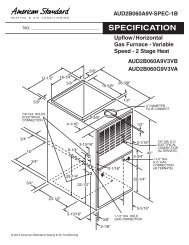
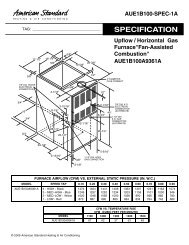
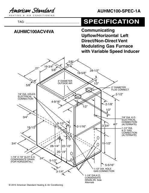
AUHMC100-SPEC-1ATAG: _________________________________AUHMC100ACV4VASPECIFICATION<strong>Co</strong>mmunicatingUpflow/Horizontal LeftDirect/Non-Direct VentModulating Gas Furnacewith Variable Speed Inducer5/8"21"19-3/4"5/8"19-5/8"28-1/2"5/8"3" DIAMETEROUTSIDE AIR1/2"2" DIAMETERFLUE CONNECT7/8" DIA. HOLESELECTRICALCONNECTION4-9/16"9"1/2"2-1/8"1/2"2-1/2"3/4"19-1/2"9-1/2"2-1/16"3-3/4"40"7/8" DIA. K.O.ELECTRICALCONNECTION(ALTERNATE)1-1/2" DIA.K.O. GASCONNECTION(ALTERNATE)3/4"28-1/4"22-1/2"19-1/2"20-1/4"1-7/8" X 7/8" SLOT K.O.CONDENSATE DRAIN(FOR HORIZONTAL)24"5-1/2"3-1/4"© 2010 American Standard Heating & Air <strong>Co</strong>nditioning5-5/16"1-1/2" DIA. HOLEGAS CONNECTION1-1/8" DIA.K.O.CONDENSATEDRAIN (Rt. SideAlternate
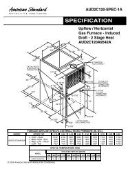
AUHMC100 Airflow - HeatingHeating*UHMC100ACV4VA** Furnace Heating Airflow (CFM) and Power (Watts) vs. External Static Pressure With FilterAirflow Target AirflowSetting (See Note 5)40% (low)Heat65%(medium)Heat100%(high)HeatLowMedium LowMedium**606639672High 743Low 1051Medium Low 1109Medium** 1166High 1289Low 1460Medium Low 1540Medium** 1620High 1790External Static Pressure0.1 0.3 0.5 0.7 0.9CFM 592 617 623 617 606Temp. Rise 61 59 58 59 60Watts 78 109 141 173 233CFM 626 651 655 649 639Temp. Rise 58 56 55 56 57Watts 79 110 142 175 236CFM 660 684 688 682 671Temp. Rise 55 53 53 53 54Watts 81 111 144 177 241CFM 732 755 757 751 739Temp. Rise 50 48 48 48 49Watts 87 115 149 185 254CFM 1048 1065 1060 1052 1038Temp. Rise 60 59 59 60 61Watts 149 169 208 252 358CFM 1107 1123 1116 1108 1094Temp. Rise 57 56 56 57 58Watts 167 186 226 271 386CFM 1165 1181 1173 1165 1150Temp. Rise 54 53 54 54 55Watts 187 204 245 292 417CFM 1291 1304 1293 1284 1269Temp. Rise 49 48 49 49 50Watts 236 250 293 343 490CFM 1466 1476 1461 1451 1435Temp. Rise 60 59 60 60 61Watts 319 330 374 430 613CFM 1548 1556 1540 1529 1512Temp. Rise 57 56 57 57 58Watts 364 373 419 476 679CFM 1629 1637 1618 1608 1590Temp. Rise 54 54 54 54 55Watts 413 419 467 527 750CFM 1803 1807 1785 1774 1755Temp. Rise 49 48 49 49 50Watts 529 532 582 646 864Notes:1. * First letter may be "A" or "T".2. ** Factory setting.3. <strong>Co</strong>ntinuous Fan Setting: Heating or cooling airflow is approximately 50% of selectedcooling value.4. LOW 350 cfm/ton is recommended for variable speed application for COMFORT & HUMIDCLIMATE setting; NORMAL is 400 cfm/ton; HIGH 450 cfm/ton is for DRY CLIMATE setting.5. Target airflow is field selectable for third stage heating. Target airflow for first and secondstage heating are percentages of third stage target and are not field selectable.<strong>Co</strong>olingAUHMC100 Airflow - <strong>Co</strong>oling*UHMC100ACV4VA** Furnace <strong>Co</strong>oling Airflow (CFM) and Power (Watts) vs. External StaticPressure With FilterUnit AirflowExternal Static PressureOutdoor Setting0.1 0.3 0.5 0.7 0.9290 CFM/ton310 CFM/ton330 CFM/tonCFMCFMCFM714765816734784834739789838733782831722770819WattsWattsWatts7988961181281381571681791942062202312442582.5350 CFM/tonCFM 868 884 887 880 867Watts 103 149 192 234 273370 CFM/tonCFM 919 934 936 929 916Watts 117 161 205 249 290400 CFM/ton430 CFM/ton450 CFM/ton290 CFM/ton310 CFM/ton330 CFM/tonCFMCFMCFMCFMCFMCFM99510721123862924985100910841134879939999100910831132882941100010021075112487593499298910611110863921979WattsWattsWattsWattsWattsWatts1351561711051181331812042201481621782272532711902072242743023222322502703163463682722913133350 CFM/tonCFM 1046 1059 1059 1051 1037Watts 149 196 244 292 336370 CFM/tonCFM 1108 1119 1117 1109 1095Watts 167 215 265 316 362400 CFM/ton430 CFM/ton450 CFM/ton290 CFM/ton310 CFM/ton330 CFM/tonCFMCFMCFMCFMCFMCFM120012921353101110821154120912991359102410941164120612941353102410931162119712851344101710851153118312701328100310711139WattsWattsWattsWattsWattsWatts1972322581391591812482863141852072313013433732322562833554004322793063354044534883223513823.5350 CFM/tonCFM 1225 1234 1230 1222 1207Watts 206 258 312 367 417370 CFM/tonCFM 1297 1304 1299 1290 1275Watts 234 288 345 402 455400 CFM/ton430 CFM/ton450 CFM/ton290 CFM/ton310 CFM/ton330 CFM/tonCFMCFMCFMCFMCFMCFM140415121583115912411323140915141584116912491329140215051574116712451324139314951564115812361315137714781546114412211299WattsWattsWattsWattsWattsWatts2813363771832122443403994442332643004004645122853193584625305803373744165205956503854254704350 CFM/tonCFM 1404 1409 1402 1393 1377Watts 281 340 400 462 520370 CFM/tonCFM 1486 1489 1481 1471 1454Watts 322 384 448 513 576400 CFM/ton430 CFM/ton450 CFM/tonCFMCFMCFM160917321813160917301810159917161795158817051783157116871765WattsWattsWatts393475536461550617530624694599698772671781864Notes:1. * First letter may be "A" or "T".2. ** Factory setting.3. <strong>Co</strong>ntinuous Fan Setting: Heating or cooling airflow is approximately 50% of selectedcooling value.4. LOW 350 cfm/ton is recommended for variable speed application for COMFORT & HUMIDCLIMATE setting; NORMAL is 400 cfm/ton; HIGH 450 cfm/ton is for DRY CLIMATE setting.NOTE:CONTINUOUS fan mode during COOLING operationmay not be appropriate in humid climates. Ifthe indoor air exceeds 60% relative humidity orsimply feels uncomfortably humid, it is recommendedthat the fan only be used in the AUTOmode.
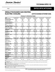
Airflow AdjustmentCheck inlet and outlet air temperatures to make sure theyare within the range specified on the Furnace rating nameplate.If the airflow needs to be increased or decreased,see the Airflow Label on the Furnace or the unit’s ServiceFacts for information on changing the speed of the BlowerMotor for your specific model. Blower speed changes aremade on the User Interface.INDOOR BLOWER TIMINGHeating: The Integrated Furnace <strong>Co</strong>ntrol module controlsthe Indoor Blower. The Blower start is fixed at 45 secondsafter ignition. The FAN-OFF period is field selectable by theUser Interface at 60, 100, 140, or 180 seconds. The factorysetting is 100 seconds.MODELTYPERATINGS 240% (low) heat Input BTUH40% (low) heat Capacity BTUH (ICS) 3100% (high) heat Input BTUH100% (high) heat Capacity BTUH (ICS) 3Temp. rise (Min.-Max.) °F.AFUEBLOWER DRIVEDiameter - Width (In.)No. UsedSpeeds (No.)CFM vs. in. w.g.Motor HPR.P.M.Volts / Ph / HzCOMBUSTION FAN - TypeDrive - No. SpeedsMotor HP - RPMVolts / Ph / HzFLAFILTER — Furnished?Type RecommendedHi Vel. (No.-Size-Thk.)VENT — Size (in.)HEAT EXCHANGERType -Fired-UnfiredGauge (Fired)ORIFICES — MainNat. Gas. Qty. — Drill SizeL.P. Gas Qty. — Drill Size 5GAS VALVEPILOT SAFETY DEVICETypeBURNERS — TypeNumberPOWER CONN. — V / Ph / Hz 4Ampacity (In Amps)Max. Overcurrent Protection (Amps)PIPE CONN. SIZE (IN.)DIMENSIONSCrated (In.)WEIGHTShipping (Lbs.) / Net (Lbs)AUHMC100ACV4VAUpflow/ Horizontal Left40,00038,000100,00095,00035 - 6595.0DIRECT10 x 101VariableSee Fan Performance Table1Variable115/1/60CentrifugalDirect - Variable1/50 - 500033 - 110/3/60 - 1801.0YesHigh Velocity1 - 20x25 - 1 in.3 RoundAluminized Steel - Type I205 — 455 — 56Redundant - Three StageHot Surface IgniterMultiport Inshot5115/1/6013.5201/2H x W x D41-3/4 x 23 x 30-1/2197 / 1851 Central Furnace heating designs are certified to ANSI Z21.47 / CSA 2.3.2 For U.S. applications, above input ratings (BTUH) are up to 2,000 feet, derate 4%per 1,000 feet for elevations above 2,000 feet above sea level.For Canadian applications, above input ratings (BTUH) are up to 4,500 feet, derate4% per 1,000 feet for elevations above 4,500 feet above sea level.3 Based on U.S. government standard tests.4 The above wiring specifications are in accordance with National Electrical <strong>Co</strong>de;however, installations must comply with local codes.5 Furnace ships in natural gas configuration. The LP conversion kit used with themodulating furnace is BAYLPSS220B or BAYLPKT220B.
Mechanical SpecificationsMODULATING OPERATIONThe modulating gas valve provideslonger heating cycles for more consistentheating comfort. Modulates from40% to 100% of the normal firing ratesin less than 1% increments of the furnace'sheating capacity saving energy,while at the same time providing maximumhomeowner comfort.COMMUNICATING MODEFurnace is shipped ready to be connectedin communicating mode usingthree wire hook-up using ACONT900comfort control.ALTERNATE 24V MODEFurnace is field cofigurable to 24Vnon-communicating mode.COMFORT CONTROLAcculink II TM <strong>Co</strong>mmunicating furnacedesign, offers plug and play – walkaway installation. Assures the entireheating and air conditioning systemis set up in the proper modes to optimizethe engineered performance ofthe matched system installed. Thefurnace can also be connected in24V mode.NATURAL GAS MODELSCentral Heating furnace designs arecertified by the American Gas Associationfor both natural and L.P. gas. Limitsetting and rating data were establishedand approved under standardrating conditions using American NationalStandards Institute standards.SAFE OPERATIONThe Integrated System <strong>Co</strong>ntrol hassolid state devices, which continuouslymonitor for presence of flame, whenthe system is in the heating mode ofoperation. Dual solenoid combinationgas valve and regulator provide additionalsafety.QUICK HEATINGDurable, cycle tested, heavy gaugealuminized steel heat exchanger quicklytransfers heat to provide warmconditioned air to the structure. Lowenergy power vent blower, to increaseefficiency and provide a positive dischargeof gas fumes to the outside.BURNERSMulti-port In-shot burners will giveyears of quiet and efficient service. Allmodels can be converted to L.P. gaswithout changing burners.INTEGRATED SYSTEM CONTROLExclusively designed operational programprovides total control of furnacelimit sensors, blowers, gas valve,flame control and includes self diagnosticsfor ease of service. Alsocontains connection points for EACand Humidifier.AIR DELIVERYThe variable speed blower motor hassufficient airflow for most heating andcooling requirements and will switchfrom heating to cooling speeds on demandfrom room thermostat. Theblower door safety switch will preventor terminate furnace operation whenthe blower door is removed.SECONDARY HEAT EXCHANGERThe Freedom 95 has a special type29-4C stainless steel secondaryheat exchanger to reclaim heat fromflue gases which would normally belost.STYLINGHeavy gauge steel and “wrap-around”cabinet construction is used in the cabinetwith baked-on enamel finish forstrength and beauty. The heat exchangersection of the cabinet is completelylined with foil faced fiberglass insulation.This results in quiet and efficient operationdue to the excellent acoustical andinsulating qualities of fiberglass. Built-inbottom pan and alternate bottom, left orright side return air connection provision.FEATURES AND GENERALOPERATIONThe Freedom 95 High Efficiency GasFurnaces utilize an Adaptive Heat UpSilicon Nitride Hot Surface Ignition system,which eliminates the waste of aconstant burning pilot. The integratedsystem control lights the main burnersupon a demand for heat from the roomthermostat. <strong>Co</strong>mplete front service access.a. Low energy power venterb. Vent proving pressure switch.American Standard Heating & Air <strong>Co</strong>nditioning has a policyof continuous product and product data improvement and itreserves the right to change specifications and design withoutnotice.American StandardHeating & Air <strong>Co</strong>nditioning6200 Troup HighwayTyler, TX 75711www.americanstandardair.com