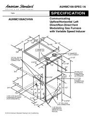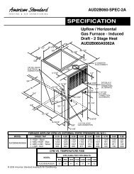
American Standard ACONT802AS32DA Touch Screen and ...
American Standard ACONT802AS32DA Touch Screen and ...
American Standard ACONT802AS32DA Touch Screen and ...
- No tags were found...

You also want an ePaper? Increase the reach of your titles
YUMPU automatically turns print PDFs into web optimized ePapers that Google loves.
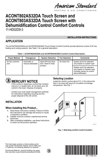
<strong>ACONT802AS32DA</strong> <strong>Touch</strong> <strong>Screen</strong> <strong>and</strong>ACONT803AS32DA <strong>Touch</strong> <strong>Screen</strong> withDehumidification Control Comfort Controls11-HD02D9-3APPLICATIONINSTALLATION INSTRUCTIONSThe <strong>ACONT802AS32DA</strong> <strong>and</strong> ACONT803AS32DA <strong>Touch</strong> <strong>Screen</strong> Comfort Controls provide electronic control of 24 Vacheating <strong>and</strong> cooling systems. See Table 1 for a general description.Table 1. <strong>ACONT802AS32DA</strong> <strong>and</strong> ACONT803AS32DA Comfort Control Description.Power Method Changeover System Selection Fan Selection Comments24 Vac commonwireAutomatic ormanual selectableHeat-Off-Cool-Auto(Em. Heat for heatpumps)On-Auto-CircSystem <strong>and</strong> Fan selectionvary based on system typeSystem <strong>and</strong> Fan selectionvary based on System type.Humidity sensor to controldehumidification.MERCURY NOTICEIf this control is replacing a control that containsmercury in a sealed tube, do not place your oldcontrol in the trash. Dispose of properly.Selecting LocationInstall the comfort control about 5 ft. (1.5m) above thefloor in an area with good air circulation at averagetemperature. See Fig. 1.Contact your local waste management authorityfor instructions regarding recycling <strong>and</strong> theproper disposal of the old control.INSTALLATIONYESNOWhen Installing this Product...1. Read these instructions carefully. Failure to followthe instructions can damage the product or causea hazardous condition.2. Installer must be a trained, experienced servicetechnician.3. After completing installation, use these instructionsto check out the product operation.NONO5 FEET[1.5 METERS]M19925Fig. 1. Selecting comfort control location.This thermostat contains a Lithium battery whichmay contain Perchlorate material. Due to State Lawin California, the following statement is required:Perchlorate Material—special h<strong>and</strong>ling may apply,See www.dtsc.ca.gov/hazardouswaste/perchlorate69-1788-03
<strong>ACONT802AS32DA</strong> TOUCH SCREEN AND ACONT803AS32DA TOUCH SCREEN WITH DEHUMIDIFICATIONHEAT/COOLHEAT/COOLY2W2S1S21RCRW1YGBY2W2S1S21RCRW1YGB2T2TRYGW1W2W3B/CAIRHANDLERRBKOYLOYGW1W2B/CVARIABLE SPEEDTWO-STAGEFURNACE/VARIABLESPEED AIR HANDLERINDOOROUTDOORINDOOROUTDOORYODTBCOOLING UNITO.D. SECTION(SINGLE STAGE)Y1Y2BCOOLING UNITO.D. SECTION(TWO STAGE)TO POWER SUPPLYPER LOCAL CODES(3 PHONLY)TO POWER SUPPLYPER LOCAL CODES(3 PHONLY)1FACTORY INSTALLED JUMPER.OPTIONAL OUTDOOR OR INDOOR REMOTE SENSOR. AVAILABLE2 ON SELECT MODELS. WIRES MUST HAVE A CABLE SEPARATEFROM THE THERMOSTAT CABLE.M22637Fig. 5. Typical hookup of single-stage heat <strong>and</strong> coolsystem with single transformer (1H/1C).1FACTORY INSTALLED JUMPER.2 OPTIONAL OUTDOOR OR INDOOR REMOTE SENSOR. AVAILABLEON SELECT MODELS. WIRES MUST HAVE A CABLE SEPARATEFROM THE THERMOSTAT CABLE.M22640Fig. 7. Typical hookup of two-stage indoor <strong>and</strong> twostagecooling unit in a single transformer system (2H/2C or 2H/1C or 1H/2C).HEAT/COOLHEAT/COOLY2W2S1S21TRCRW1YGBY2W2S1S223T1RCRW1YGBRYGTTWB/COILFURNACERBKOYLOYGW1W2B/CVARIABLE SPEEDTWO STAGEFURNACEYOIL BURNER PRIMARYINDOOROUTDOORTO POWER SUPPLYPER LOCAL CODESB(3 PHONLY)COOLING UNITO.D. SECTION(SINGLE STAGE)1Y2Y1TO POWER SUPPLYPER LOCAL CODESFACTORY INSTALLED JUMPER.B(3 PHONLY)INDOOROUTDOOR16 SEERCOOLING UNITO.D. SECTION(TWO STEP)1OPTIONAL OUTDOOR OR INDOOR REMOTE SENSOR. AVAILABLEON SELECT MODELS. WIRES MUST HAVE A CABLE SEPARATEFROM THE THERMOSTAT CABLE.M2263823OPTIONAL OUTDOOR OR INDOOR REMOTE SENSOR. AVAILABLEON SELECT MODELS. WIRES MUST HAVE A CABLE SEPARATEFROM THE THERMOSTAT CABLE.THE INSTALLER MUST JUMPER AT THE LVTB “R” TO “O”.M24231Fig. 6. Typical hookup of single-stage heat <strong>and</strong> coolsystem with two transformers (1H/1C).Fig. 8. Typical hookup of two-stage indoor <strong>and</strong>two-step scroll cooling unit in a single transformersystem (2H/2C or 2H/1C or 1H/2C).3 69-1788—03
<strong>ACONT802AS32DA</strong> TOUCH SCREEN AND ACONT803AS32DA TOUCH SCREEN WITH DEHUMIDIFICATIONHEAT PUMPY2FX2W1S1S21RCROYGB2TI-PFPM-ARYOGW1ODT-1ODT-2INDOOROUTDOORW2W3SUPPL. HTR.CONTROL BOXREQ.FORTO POWER 3 PHSUPPLY PERLOCALCODES ANDAS DEFINEDIN FIELDWIRING TABLEB/CTAIRHANDLERRYOX2/BKBR(T)BHEAT PUMPO.D. SECTION(SINGLE STAGE)TO POWER SUPPLYPER LOCAL CODES(3 PHONLY)12FACTORY INSTALLED JUMPER.OPTIONAL OUTDOOR OR INDOOR REMOTE SENSOR. AVAILABLEON SELECT MODELS. WIRES MUST HAVE A CABLE SEPARATEFROM THE THERMOSTAT CABLE.M22641Fig. 9. Typical hookup of single-stage heat pump with auxiliary/backup heat (2H/1C heat pump).HEAT PUMPY2FX2W1S1S21RCROYGB2TI-PFPM-ARBKYYLOOGW1ODT-1ODT-2INDOOROUTDOORW2W3SUPPL. HTR.CONTROL BOXREQ.FORTO POWER 3 PHSUPPLY PERLOCALCODES ANDAS DEFINEDIN FIELDWIRING TABLEB/CTVARIABLESPEED AIRHANDLERRY2Y1OX2/BKBR(T)FBHEAT PUMPO.D. SECTION(TWO STAGE)TO POWER SUPPLYPER LOCAL CODES(3 PHONLY)1 FACTORY INSTALLED JUMPER.2 OPTIONAL OUTDOOR OR INDOOR REMOTE SENSOR. AVAILABLE ON SELECT MODELS.WIRES MUST HAVE A CABLE SEPARATE FROM THE THERMOSTAT CABLE.M22642Fig. 10. Typical hookup of multistage heat pump with auxiliary/backup heat (3H/2C heat pump).69-1788—03 4
<strong>ACONT802AS32DA</strong> TOUCH SCREEN AND ACONT803AS32DA TOUCH SCREEN WITH DEHUMIDIFICATIONHEAT PUMPY2FX2W1S1S21RCROYGB2T3RBKOGYLOYW1W2B/CVARIABLE SPEEDAIR HANDLERINDOOROUTDOORR Y2 Y1 O X2/BK BR(T)TO POWER SUPPLYPER LOCAL CODESB(3 PHONLY)16 SEERHEAT PUMPO.D. SECTION(TWO STEP)123FACTORY INSTALLED JUMPER.OUTDOOR REMOTE SENSOR. WIRES MUST HAVE A CABLESEPARATE FROM THE THERMOSTAT CABLE.THE INSTALLER MUST JUMPER AT THE LVTB “R” TO “O”.M24230Fig. 11. Typical hookup of multistage two-step scroll heat pump with auxiliary/backup heat (3H/2C heat pump).HEAT PUMPY2FX2W11RCROY2TS1S2GBRG Y W1 W2 B/CNON-V.S.ONE OR TWOSTAGE GASFURNACEINDOOROUTDOORR Y O X2/BK BR(T)BHEAT PUMPO.D. SECTION(SINGLE STAGE)12TO POWER SUPPLYFACTORY INSTALLED JUMPER. PER LOCAL CODESOUTDOOR REMOTE SENSOR. WIRES MUST HAVE ACABLE SEPARATE FROM THE THERMOSTAT CABLE.(3 PHONLY)M24200Fig. 12. Typical hookup of singe-stage heat pump with non-variable speed gas furnace.5 69-1788—03
<strong>ACONT802AS32DA</strong> TOUCH SCREEN AND ACONT803AS32DA TOUCH SCREEN WITH DEHUMIDIFICATIONHEAT PUMPY2FX2W11RCROY2TS1S2GB1RBK O G YLO Y W1 W2 B/CVARIABLESPEEDTWO STAGEFURNACEINDOOROUTDOORR Y O BR/X2 BR(T)OR BKBHEAT PUMPO.D. SECTION(SINGLE STAGE)12TO POWER SUPPLYFACTORY INSTALLED JUMPER. PER LOCAL CODESOUTDOOR REMOTE SENSOR. WIRES MUST HAVE ACABLE SEPARATE FROM THE THERMOSTAT CABLE.(3 PHONLY)M24201Fig. 13. Typical hookup of single-stage heat pump with two-stage variable speed gas furnace(2H/1C heat pump).69-1788—03 6
<strong>ACONT802AS32DA</strong> TOUCH SCREEN AND ACONT803AS32DA TOUCH SCREEN WITH DEHUMIDIFICATIONHEAT PUMPY2FX2W11RCROY2TS1S2GB1RBKOGY1/Y/Y2 W1 W2 B/CYLOVARIABLESPEEDTWO STAGEFURNACEINDOOROUTDOORR Y2 Y1 O X2/BK BR(T)FBHEAT PUMPO.D. SECTION(TWO STAGE)12TO POWER SUPPLYFACTORY INSTALLED JUMPER. PER LOCAL CODESOUTDOOR REMOTE SENSOR. WIRES MUST HAVE ACABLE SEPARATE FROM THE THERMOSTAT CABLE.(3 PHONLY)M24202Fig. 14. Typical hookup of multistage heat pump with two-stage variable speed gas furnace (3H/2C heat pump).7 69-1788—03
<strong>ACONT802AS32DA</strong> TOUCH SCREEN AND ACONT803AS32DA TOUCH SCREEN WITH DEHUMIDIFICATIONHEAT PUMPY2FX2W11RCROY2TS1S2GB1RBK O G YLO Y W1 W2 B/C3VARIABLESPEEDTWO STAGEFURNACEINDOOROUTDOORR Y2 Y1 O X2/BK BR(T)B16 SEERHEAT PUMPO.D. SECTION(TWO STEP)123TO POWER SUPPLYFACTORY INSTALLED JUMPER.PER LOCAL CODESOUTDOOR REMOTE SENSOR. WIRES MUST HAVE ACABLE SEPARATE FROM THE THERMOSTAT CABLE.REMOVE / CUT JUMPER FROM R TO BK.(3 PHONLY)M24203Fig. 15. Typical hookup of multistage two-step scroll heat pump with two-stage variable speed gas furnace(3H/2C heat pump).Powering the Comfort ControlThe comfort control can be powered with 24 Vac.24 Vac Common Power (Recommended)Wire the common side of the transformer to the B screwof the comfort control wallplate. When installing in a singletransformer system, keep the jumper wire between the R<strong>and</strong> Rc screws. When installing in a two-transformersystem, use the common from the cooling transformer toconnect to the B screw <strong>and</strong> remove the jumper wirebetween the R <strong>and</strong> Rc screws.Three AAA alkaline batteries can be used to power thecomfort control for armchair programming only. To preventthe comfort control <strong>and</strong> heating/cooling system fromshutting down due to lack of battery power, it is notrecommended that the comfort control be solely poweredwith the three AAA batteries during normal systemoperation. When using batteries, make sure positive <strong>and</strong>negative terminals are oriented correctly, as marked onthe device. See Fig. 16.Battery Power (Optional)CAUTIONEquipment or Property Damage Hazard.Using battery power only may not provideadequate power to comfort control <strong>and</strong> cancause damage during freezing conditions.Connect the 24 Vac Common (B) wire from thesystem transformer to the comfort control forproper operation when the battery power isdrained.BATTERIES (3)M19918Fig. 16. Installing batteries on comfort control back.69-1788—03 8
<strong>ACONT802AS32DA</strong> TOUCH SCREEN AND ACONT803AS32DA TOUCH SCREEN WITH DEHUMIDIFICATIONMounting the Comfort Control1. Align the terminal screw blocks with the pins on theback of the comfort control.2. Push the comfort control straight onto the wallplate.See Fig. 17.This comfort control is designed to automatically keep thecurrent time <strong>and</strong> day in memory for up to ten years undernormal use once the calendar is set. When the comfortcontrol is first powered, the display is ready for thecalendar date to be entered. See Fig. 19.WALLSET CURRENT DAYSET MONTHWED MON TUE THU FRI SATSUNDONEREMOVE DURINGINSTALLATIONUSE ARROWS TO SET YEAR AND TIMEM22643Fig. 17. Mounting comfort control on wallplate.Adjusting Real-Time ClockSetting Calendar <strong>and</strong> TimeLocate <strong>and</strong> remove the tab labeled Remove in the lowerleft corner on the comfort control back. The tab must beremoved to activate the real-time clock. See Fig. 18.MON WED THU FRI SATOK TO PICK MULTIPLE DAYS SCREEN LOCKEDCHANGE FILTER UV LAMP HUMIDIFIER PADDONESUNM22645REMOVE TAB TO ACTIVATE REAL TIME CLOCKFig. 19. Setting calendar <strong>and</strong> time after initialpowerup.REMOVE DURINGINSTALLATIONREMOVE DURINGINSTALLATIONM22644Fig. 18. Removing tab to activate real-time clock.IMPORTANTThe tab on the back of the comfort control in thelower left corner must be removed for thisfeature to be active.Using the Comfort ControlThe comfort control has a touch screen interface. Wordsor symbols appear, highlighting the keys as necessary tocomplete tasks. Always press the keys with yourfingertips. Sharp instruments like a pen or pencil point c<strong>and</strong>amage the comfort control.1. Use the arrow keys to set the Year, Month <strong>and</strong> Day,as shown in Fig. 19.2. Press the Done key.3. Use the arrow keys to set the current time. SeeFig. 19.4. Press the Done key.9 69-1788—03
<strong>ACONT802AS32DA</strong> TOUCH SCREEN AND ACONT803AS32DA TOUCH SCREEN WITH DEHUMIDIFICATIONOPERATIONSystem <strong>and</strong> Fan SettingsThe System default setting is Heat <strong>and</strong> the Fan defaultsetting is Auto.SYSTEM SETTINGSHeat: controls heating system.Off: heating <strong>and</strong> cooling are off.Cool: controls cooling system.Auto: automatically changes between heating <strong>and</strong> coolingsystems, depending on indoor temperature. (See InstallerSetup section.)Em Heat: emergency heat cycles to maintaintemperature. Compressor is locked out. (Used only forheat pump systems with backup heat.)CFEQUIPMENTMONITORTO CTO RM22646Fig. 20. F terminal switch to R (power) side of systemtransformer.Preprogrammed SettingsTable 3 shows the default program settings. See Owners’Guide for complete instructions on changing the program.FAN SETTINGSThe Fan setting can be programmed into the comfortcontrol schedule for each period (Wake, Leave, Return,Sleep). See the Owners’ Guide for additional information.LED Indication (Requires 24 Vac CommonConnection)An LED indicator is located in the upper right corner of thecomfort control. It is only visible when lighted:• It indicates when the comfort control is in theEmergency Heat mode. When in Em. Ht. mode, the Fterminal is continuously energized <strong>and</strong> the LED is on.• When the F terminal is wired to an equipment monitor,the LED signals when a check or fail signal is sent tothe comfort control from the system. See Fig. 20. (Thiscan occur only when the comfort control is not in Em.Ht. mode.)Table 3. Default Program Settings.SchedulePeriod Time HeatWake 6:00AM 70 ° F(21 ° C)Leave 8:00AM 62 ° F(16.5 ° C)Return 6:00PM 70 ° F(21 ° C)Sleep10:00PM 62 ° F(16.5 ° C)SetpointsCool78 ° F(25.5 ° C)85 ° F(29.5 ° C)78 ° F(25.5 ° C)82 ° F(28 ° C)FanSettingAutoAutoAutoAuto69-1788—03 10
<strong>ACONT802AS32DA</strong> TOUCH SCREEN AND ACONT803AS32DA TOUCH SCREEN WITH DEHUMIDIFICATIONINSTALLER SETUPThe comfort control works with many different systemtypes. To operate correctly, the comfort control must beset up to operate the installed heating <strong>and</strong>/or coolingsystem.4. Release the two blank keys when the screen on thecomfort control matches the screen below.Follow these steps to enter the Installer Setup:1. Be sure the comfort control is powered.2. Press <strong>and</strong> release the System Key.THUFANON InsideAUTOSet ToDONESYSTEMEM HEATFollowingScheduleOFFCOOLAMM22649SCHED HOLD CLOCK SCREEM226473. Press <strong>and</strong> hold the two blank keys on either side ofthe center blank key for approximately five secondsuntil screen changes.5. See screen below to review how the comfort controlkeys are used during Installer Setup. See Table 4for the Installer Setup Numbers <strong>and</strong> Settings.INSTALLERSETUPNUMBERADVANCE TO NEXTINSTALLER SETUPCURRENTSETTINGMO TU WE TH FR SA SUInsideSet ToSYSTEMEMHEATFollowingScheduleMON WED THU FRI SATSUNOFFDONECANCDONEM22648PRESS TO EXITINSTALLER SETUPCHANGE THECURRENTSETTINGM226506. Press the Done key to exit the Installer Setupscreen.11 69-1788—03
<strong>ACONT802AS32DA</strong> TOUCH SCREEN AND ACONT803AS32DA TOUCH SCREEN WITH DEHUMIDIFICATIONIMPORTANTThe Installer Setup Menu (Table 4) shows all the available options. These options customize themselves asyou make selections to the Installer Setup. Therefore, not all Installer Setup Selections are shown or are availableto change.Table 4. Installer Setup Menu.Factory SettingOther ChoicesSelectNot used.Date (YearUpper)Date (YearLower)InstallerSetupNumber1 thru0099Option Description Options DescriptionComments— — — — —0120 20 Set first two digits ofcurrent calendar year(20 for year 2005, etc)0130 05 Represents last twodigits of currentcalendar year (2005).Date (Month) 0140 6 Digit(s) representscurrent calendarmonth.Date 0150 15 Digit(s) represents(Day)current calendar date.ScheduleOptionsSystem TypeSelection21 21 —first two digits of currentcalendar year (21xx)00 -99 Select last two digits of currentcalendar year.1-12 Select number that representscurrent calendar month.2000 -2178 available2000 -2178 available1-31 Select number that represents —current calendar date.0160 4 7-day programming 0 0—nonprogrammable —0170 1 1 Heat/1Cool 1-12 1—1heat/1coolAvailable options <strong>and</strong>2—single-stage heat pump (no defaults vary byaux. heat)3—heat only (no fan)4—heat only (with fan)comfort controlSystem selectionautomatically5—hot water Series 20 (3-wire modifies someor normally open zone valves)6—cool only7—2 heat/1cool heat pump8—2 heat/2 cooldefault settings <strong>and</strong>/or hides otherInstaller Setupoptions.9—2 heat/1cool10—1 heat/2 cool oil furnaceor 0H/2C11—2 heat/2 cool heat pump(with no auxiliary heat)12—3 heat/2 cool heat pump(with auxiliary heat)Fan Operation 0180 0 Heat/Coolapplications whereequipment controlsfan operation in heatmode.Backup HeatSource(AuxiliaryHeat)ExternalFossil Fuel KitCycles perhour (cph) for1st StageCompressorCycles perhour (cph) for2nd StageCompressor1 Heat pump or electric heatapplications where comfortcontrol controls fan operationin heat mode.0200 0 Heat pump backup 1 Heat pump backup heatheat source is electric. source is fossil fuel.0210 1 External fossil fuel kitis controlling heatpump backup heat(recommended).0220 3 Compressor Stage 1cycles per hour (cph)0230 3 Compressor Stage 2cycles per hour (cph)—Only shown if heat/cool system isselected. If heatpump is chosen, f<strong>and</strong>efaults to electric.Only shown if 2 heat/1 cool or 3 heat/2cool heat pump ischosen.0 No external fossil fuel kit iscontrolling heat pump backupheat. This comfort controlcontrols the backup fossil fuelheat with outdoor sensor.Only shown if fossilfuel is chosen asbackup heat source.1-6 1-6 available;3 is recommended.1-6 1-6 available;3 is recommended.—Only shown if twostages of cool areselected.69-1788—03 12
<strong>ACONT802AS32DA</strong> TOUCH SCREEN AND ACONT803AS32DA TOUCH SCREEN WITH DEHUMIDIFICATIONTable 4. Installer Setup Menu. (Continued)Factory SettingOther ChoicesSelectCycles perhour (cph) for1st StageHeatCycles perhour (cph) for2nd StageHeatCycles perhour (cph) for3rd StageHeatNumber0240 5 Heat Stage 1 cyclesper hour (cph)0250 5 Cycles per hour (cph)for 2nd Stage Heat orAuxiliary Heat for2 H/1C Heat PumpSystems0260 9 Cycles per hour (cph)for Auxiliary Heat in3H/2C Heat PumpSystemsCycles per 0270 9 Cycles per hour (cph)hour (cph) forfor Emergency HeatEm HeatContinuousBacklightInstallerSetupOption Description Options Description0280 0 Backlight not oncontinuously. Comfortcontrol backlightcomes on with eachkey press.Comments1-12 1-12 available; typical settings: Not shown if system1—1 cph used for steam or selection is heatgravity system.pump. Selection in3—3 cph used for 2-stage this stage changesfossil fuel forced air systems or default cph for 2ndhot water systems.stage heat.5—5 cph used for single-stagefossil fuel forced air systems.9—9 cph used for electricforced air heat systems(electric auxiliary heat for heatpump systems).1-12 1-12 available; typical settings: Only shown if two1—1 cph used for steam or stages of heat aregravity system.selected.3—3 cph used for 2-stagefossil fuel forced air systems orhot water systems.5—5 cph used for single-stagefossil fuel forced air systems.9—9 cph used for electricforced air heat systems(electric auxiliary heat for heatpump systems).1-12 1-12 available; typical settings: Only shown if 3H/2C1—1cph used for steam or heat pump system isgravity system.selected.3—3 cph used for 2-stagefossil fuel forced air systems orhot water systems.5—5 cph used for single-stagefossil fuel forced air systems.9—9 cph used for electricforced air heat systems.(electric auxiliary heat for heatpump systems).1-12 1-12 is available; typicalsettings:3—3 cph used for 2-stagefossil fuel forced air systems orhot water systems.5—5 cph used for single-stagefossil fuel forced air systems.9—9 cph used for electricforced air heat systems(electric auxiliary heat for heatpump systems).1 Backlight is on continuously(comfort control must have acommon wire attached for thisfunction).Only shown if 2 heat/1 cool or 3 heat/2cool heat pump isselected.Option is alwaysshown; however,continuously onbacklight works only ifcomfort control iswired with 24 VacCommon.Changeover 0300 0 Manual changeover 1 1—auto changeover —13 69-1788—03
<strong>ACONT802AS32DA</strong> TOUCH SCREEN AND ACONT803AS32DA TOUCH SCREEN WITH DEHUMIDIFICATIONTable 4. Installer Setup Menu. (Continued)Factory SettingOther ChoicesSelect NumberDeadb<strong>and</strong> 0310 2 thru 9 Heating <strong>and</strong> coolingsetpoints can be setno closer than chosenvalue:2—2 ° F (1 ° C)3—3 ° F (2 ° C)4—4 ° F (2.5 ° C)5—5 ° F (3 ° C)6—6 ° F (3.5 ° C)7—7 ° F (4 ° C)8—8 ° F (4.5 ° C)9—9 ° F (5 ° C)TemperatureIndicationScaleDaylightSavingsRemoteTemperatureSensor(Outdoor orIndoor)Heat PumpCompressorLockoutHeat PumpAuxiliaryLockoutOption Description Options Description3 Heating <strong>and</strong> cooling setpointscan be set no closer than 3 ° F(1.5 ° C).0320 0 Temperature isdisplayed in ° F.0330 1 Daylight savingsenabled (use through2006 <strong>and</strong> for areasthat do not use thenew 2007 DSTcalendar).0340 0 No remotetemperature sensor.0350 0 No compressorlockout.0360 0 No heat pumpauxiliary lockout.Indoor 0380 0 No indoorDehumidificatidehumidificationon Controlcontrol.Furnace FilterChangeReminderHumidifierPadReplacementReminderInstallerSetup0500 0 Furnace filter changereminder off.0510 0 Humidifier padreplacement reminderoff.CommentsShown only ifautomaticchangeover isselected.The deadb<strong>and</strong> isrestricted to the rangeof 5 to 9 if ISU 0380 isset todehumidificationdroop control.1 Temperature is displayed in ° C. —0, 2 0—daylight savings isdisabled.2—daylight savings enabled(use starting in 2007 for areasthat use the new 2007 DSTcalendar).1-3 1—outdoor temperaturesensor for display only.2—outdoor temperaturesensor for system control—used for select heat pumpsystems. (See Special HeatPump Features section formore details.)3—indoor temperature sensor15, 20,25, 30,35, 40,4540, 45,50, 55,6015 ° F (-9.5 ° C)20 ° F (-6.5 ° C)25 ° F (-4 ° C)30 ° F (-1 ° C)35 ° F (1.5 ° C)40 ° F (4.5 ° C)45 ° F (7 ° C)40 ° F (4.5 ° C)45 ° F (7 ° C)50 ° F (10 ° C)55 ° F (13 ° C)60 ° F (15.5 ° C)1 1—dehumidification droopcontrol.1-6 1—10 run time days2—30 run time days3—60 run time days4—90 run time days5—120 run time days6—365 run time days1-3 1— 90 calendar days2—180 calendar days3—365 calendar daysSet to 0 in areas thatdo not follow daylightsavings.Defaults <strong>and</strong> Optionsdepend on SystemType selection.Indoor TemperatureSensor uses anaveraging network<strong>and</strong> does not includeon-board sensor.Default depends onother selections.Shown if OutdoorTemperature forcontrol is selected.Shown if electric ischosen for backupheat source <strong>and</strong>outdoor temperaturesensor for control isselected.Available on modelswith humidity sensor.Run time based oncall for fan.—69-1788—03 14
<strong>ACONT802AS32DA</strong> TOUCH SCREEN AND ACONT803AS32DA TOUCH SCREEN WITH DEHUMIDIFICATIONTable 4. Installer Setup Menu. (Continued)Factory SettingOther ChoicesSelectAdaptiveIntelligentRecoveryNumber ofPeriodsMinimumCompressorOff TimeHeatTemperatureRange StopCoolTemperatureRange StopNumber0530 1 Adaptive IntelligentRecovery control isactivated (systemstarts early so setpointis reached by start ofprogram period).Option Description Options Description0 0—conventional recovery(system starts recovery atprogrammed time)0540 4 Four periods available(Wake, Leave, Return,Sleep)0580 5 Five minute minimumoff time forcompressor.0600 90 Highest heatingsetpoint.0610 50 Lowest coolingsetpoint.2 Two periods available (Wake<strong>and</strong> Sleep)0, 2, 3,4Minimum number of minutescompressor is off betweencalls for compressor.40 to 89 Temperature range (1°Fincrements) of heatingsetpoint.51 to 99 Temperature range (1°Fincrements) of coolingsetpoint.Comments—Not shown ifnon-programmable isselected. 2 or 4applies to all days ofthe week.Five minutesrecommendedShown in 1/2 °C.Shown in 1/2 °C.Clock Format 0640 12 12-hour clock format. 24 24-hour clock format —Extended Fanon time HeatExtended Fanon time CoolKeypadLockoutInstallerSetup0650 0 No extended fanoperation after call forheat ends.0660 0 No extended fanoperation after call forcool ends.90 Fan operation is extended 90seconds after call for heatends.90 Fan operation is extended 90seconds after call for coolends.0670 0 Unlocked keypad. 1, 2 1—partially locked keypad2—fully locked keypadNot shown if fanoperation is set tofossil fuel or in CoolOnly SystemsNot shown in HeatOnly Systems.Unlocked—allfunctions areavailable.Partially locked—onlytemperature up <strong>and</strong>down keys <strong>and</strong> abilityto enter <strong>and</strong> modifyInstaller Setup modeare available. Fullylocked—only ability toenter <strong>and</strong> modifyInstaller Setup modeare available.15 69-1788—03
<strong>ACONT802AS32DA</strong> TOUCH SCREEN AND ACONT803AS32DA TOUCH SCREEN WITH DEHUMIDIFICATIONTable 4. Installer Setup Menu. (Continued)Factory SettingOther ChoicesSelectTemperatureControl inHeatTemperatureControl inCoolInstallerSetupNumber0680 2 <strong>St<strong>and</strong>ard</strong> temperaturecontrol in heating.Option Description Options Description0690 2 <strong>St<strong>and</strong>ard</strong> temperaturecontrol in cooling.1, 3 1—less aggressivetemperature control (couldcause temperatureundershoot)3—more aggressivetemperature control (couldcause temperature overshoot)1, 3 1—less aggressivetemperature control (couldcause temperatureundershoot)3—more aggressivetemperature control (couldcause temperature overshoot)Temperature 0700 0 No difference in -3, -2, -3 ° F (-1.5 ° C)Display Offsetdisplayed temperature -1, 0, 1, -2°F (-1°C)<strong>and</strong> actual room 2, 3 -1°F (-.5°C)temperature.0°F (0°C)1°F (.5°C)2°F (1°C)3°F (1.5°C)Reset Comfort 0710 0 No comfort controlControlreset.1 Resets all Installer SetupOptions to default values <strong>and</strong>resets schedule to defaultsetting.CommentsApplies to recoveryramp <strong>and</strong> use ofauxiliary heat duringrecovery.Choose 1 if gettingtemperatureovershoot.Choose 3 if gettingtemperatureundershoot.Applies to recoveryramp.Choose 1 if gettingtemperatureovershoot.Choose 3 if gettingtemperatureundershoot.—Only calendarsettings <strong>and</strong> time areretained.69-1788—03 16
<strong>ACONT802AS32DA</strong> TOUCH SCREEN AND ACONT803AS32DA TOUCH SCREEN WITH DEHUMIDIFICATIONSYSTEM CHECKOUTInstaller System TestThe Installer System Test mode is used to test the HVACsystem(s). See Table 5. While in System Test mode,minimum off-time for compressors is bypassed.The Installer Test is part of the Installer Setup options.Enter Installer Setup screen <strong>and</strong> press the Down arrowkey to bring up the test selection(s) quickly.CAUTIONEquipment Damage Hazard.Minimum compressor off-time is bypassedduring Installer System Test.Avoid cycling compressor quickly.Table 5. System Test(s).SelectInstallerTest CoolInstallerTest FanInstallerTest HeatInstallerTest Em HtInstallerSetupNumberFactory SettingOther ChoicesOptions Description Options DescriptionTest 1 0 Cool is off 1,2 0—cool off1—cool stage 1 turns on2—cool stages 1 <strong>and</strong> 2 onTest 2 0 Fan is off 1 0—fan off1—fan turns onTest 3 0 Heat is off 1-3 0—heat off1—stage 1 heat on2—stages 1 <strong>and</strong> 2 heat on3—stages 1, 2 <strong>and</strong> 3 (AuxHt) onTest 4 0 Emergencyheat is off1 0—emergency heat off1—emergency heat on2—emergency heat <strong>and</strong>auxiliary heat turn onCommentsSystem selectiondetermines whichtests are available<strong>and</strong> the number ofstages shown.——Available only ifheat pump withauxiliary heat isselected.17 69-1788—03
<strong>ACONT802AS32DA</strong> TOUCH SCREEN AND ACONT803AS32DA TOUCH SCREEN WITH DEHUMIDIFICATIONADVANCED FEATURESOutdoor or Indoor Temperature SensorFor accuracy, the initial reading of the indoor <strong>and</strong> outdoortemperature sensors require five minutes to stabilize. Seethe Sensor instructions for installation information.Special Heat Pump FeaturesHeat Pump with Fossil Fuel Auxiliary Heat (DualFuel) <strong>and</strong> Outdoor Temperature SensorIn this operation there is no external fossil fuel kit (dualfuel kit) installed; the comfort control controls this function.1. Choose correct heat pump application in InstallerSetup Number 0170.2. Choose Fossil Fuel Option as the backup heatsource in Installer Setup Number 0200.3. Choose No External Fossil Fuel Kit Option iscontrolling backup heat in installer Setup Number0210.4. Outdoor Temperature Sensor for Control Optionis automatically chosen in Installer Setup Number0340.5. Choose appropriate Balance Point Temperaturein Installer Setup Number 0350.OPERATION IN HEAT MODE ABOVE BALANCE POINT(OUTDOOR TEMPERATURE)When the outdoor temperature is above the selectedBalance Point Temperature (ISU 0350), only thecompressor operates <strong>and</strong> the fan (G terminal) energizeswhen the comfort control calls for heat.OPERATION IN HEAT MODE BELOW BALANCE POINT(OUTDOOR TEMPERATURE)When the outdoor temperature is below the selectedBalance Point Temperature (ISU 0350), only the FossilFuel (auxiliary heat) operates <strong>and</strong> the fan (G terminal)does not energize when the comfort control calls for heat.OPERATION IN EMERGENCY HEAT MODEThe balance point (outside) temperature is not used in theEmergency Heat mode. When the comfort control ismoved to the Emergency Heat position, the compressor islocked out. The first stage of heat is whatever isconnected to the X2 terminal. The second stage of heat iswhat is connected to the W1 terminal. Often there is onlyone source of non-compressor heat <strong>and</strong> the X2 terminal isjumpered to the W1 terminal.Heat Pump with Electric Auxiliary (Backup) Heat<strong>and</strong> Outdoor Temperature Sensor1. Choose correct heat pump application in InstallerSetup Number 0170.2. Choose Electric as Auxiliary (Backup) HeatSource in Installer Setup Number 0200.3. Choose Outdoor Temperature Sensor forControl Option in Installer Setup Number 0340.4. Choose Compressor Lockout Temperature inInstaller Setup Number 0350.5. Choose Auxiliary Lockout Temperature inInstaller Setup Number 0360.NOTE:There is a 5°F deadb<strong>and</strong> between the Compressor<strong>and</strong> Auxiliary Heat Lockout TemperaturesOPERATION IN HEAT MODEWhen the outdoor temperature is below the CompressorLockout Temperature, only the Auxiliary Heat operates.When the outdoor temperature is above the AuxiliaryLockout Temperature, only the Compressor operates.See Fig. 21.OUTDOOR TEMPERATURE5035COMPRESSOR ONLYBOTH COMPRESSOR ANDAUXILIARY HEATAUXILIARY ONLYAUXILIARYLOCKOUTTEMPERATURECOMPRESSORLOCKOUTTEMPERATUREFig. 21. Heat Pump Operation with LockoutTemperatures Set.M19950When the outdoor temperature is between the twotemperatures, both the Compressor <strong>and</strong> Auxiliary Heatoperate.OPERATION IN THE EMERGENCY HEAT MODEOnce the comfort control is placed into the EmergencyHeat mode, the compressor <strong>and</strong> auxiliary lockout featuresare turned off. In the Emergency Heat mode, thecompressor is locked out. The first stage of heat iswhatever is connected to the X2 terminal. The secondstage of heat is connected to the W1 terminal. Usually theemergency <strong>and</strong> auxiliary heat sources are electric stripheat in these cases.Dehumidification Droop ControlThe dehumidification control attempts to control to theuser's humidity setpoint by turning on the air conditioner.In extremely high humidity conditions, the comfort controlkeeps the air conditioner running for up to 3 ° F below thetemperature setpoint. It does this while trying to achievethe desired humidity setpoint <strong>and</strong> balancing that with thetemperature setpoint.69-1788—03 18
<strong>ACONT802AS32DA</strong> TOUCH SCREEN AND ACONT803AS32DA TOUCH SCREEN WITH DEHUMIDIFICATIONTROUBLESHOOTING (SEE TABLE 6)Table 6. Troubleshooting.Symptom Possible Cause ActionDisplay does not come on.Temperature settings do notchange.Heating or cooling does not comeon.Comfort control is calling for Heat(Heat on) or Cool (Cool on) but noheating or cooling is running.Comfort control does not respondwhen touch areas are pressed.Comfort control is not beingpowered.The upper or lower temperaturelimits were reached.The keypad is fully locked.Comfort control minimum offtimeis activated.System selection is not set toHeat or Cool.System type selection isincorrect.Heating or cooling equipment isnot operating.The keypad is locked.Check for 24 Vac between B <strong>and</strong> Rc.Check temperature setpoints.Check Installer Setup Numbers 0600 <strong>and</strong>0610; modify as needed.Check Installer Setup Number 0670 tochange keypad locked options.Wait up to five minutes for the system torespond.Set system Selection to correct position.Check Installer Setup Number 0170 <strong>and</strong>make sure correct System type ischosen.Check wiring.Check Installer Setup Number 0170 <strong>and</strong>make sure correct system type is chosen.Verify operation of equipment in SystemTest mode.Check Installer Setup Number 0670 tochange keypad locked options.19 69-1788—03
<strong>ACONT802AS32DA</strong> TOUCH SCREEN AND ACONT803AS32DA TOUCH SCREEN WITH DEHUMIDIFICATION® U.S. Registered Trademark • Copyright © 2008<strong>American</strong> <strong>St<strong>and</strong>ard</strong> Heating & Air Conditioning •All Rights Reserved •Pub. No. 11-HD02D9-369-1788—03 M.S. Rev. 01-08<strong>American</strong> <strong>St<strong>and</strong>ard</strong> Heating & Air ConditioningTroup HighwayTyler, TX 75711-9010