installation information emg model: emg-kfk set (emg ... - Music Station
installation information emg model: emg-kfk set (emg ... - Music Station
installation information emg model: emg-kfk set (emg ... - Music Station

You also want an ePaper? Increase the reach of your titles
YUMPU automatically turns print PDFs into web optimized ePapers that Google loves.
0230-0105A<br />
PO BOX 4394<br />
SANTA ROSA, CA<br />
95402 USA<br />
P (707) 525-9941<br />
F (707) 575-7046<br />
EMGPICKUPS.COM<br />
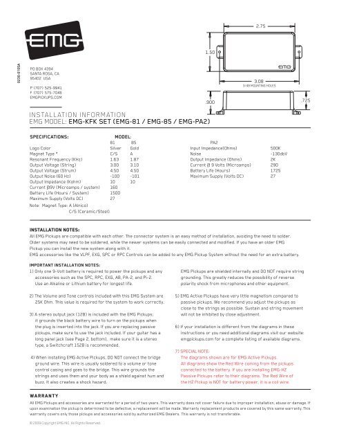
INSTALLATION INFORMATION<br />
EMG MODEL: EMG-KFK SET (EMG-81 / EMG-85 / EMG-PA2)<br />
SPECIFICATIONS: MODEL:<br />
81 85 PA2<br />
Logo Color Silver Gold Input Impedance(Ohms) 500K<br />
Magnet Type * C/S A Noise -130dbV<br />
Resonant Frequency (KHz) 1.63 1.87 Output Impedance (Ohms) 2K<br />
Output Voltage (String) 3.00 3.10 Current @ 9 Volts (Microamps) 290<br />
Output Voltage (Strum) 4.50 4.50 Battery Life (Hours) 1725<br />
Output Noise (60 Hz) -100 -101 Maximum Supply (Volts DC) 27<br />
Output Impedance (Kohm) 10 10<br />
Current @9V (Microamps / system) 160<br />
Battery Life (Hours / System) 1500<br />
Maximum Supply (Volts DC)<br />
Note: Magnet Type: A (Alnico)<br />
27<br />
C/S (Ceramic/Steel)<br />
Installation notes:<br />
All EMG Pickups are compatible with each other. The connector system is an easy method of <strong>installation</strong>, avoiding the need to solder.<br />
Older systems may need to be soldered, while the newer systems can be easily connected and modified. If you have an older EMG<br />
Pickup you can install the new system along with it.<br />
EMG accessories like the VLPF, EXG, SPC or RPC Controls can be added to any EMG Pickup System without the need for an extra battery.<br />
IMPORTANT INSTALLATION NOTES:<br />
1) Only one 9-Volt battery is required to power the pickups and any<br />
accessories such as the SPC, RPC, EXG, AB, PA-2, and Pi-2.<br />
Use an Alkaline or Lithium battery for longest life.<br />
2) The Volume and Tone controls included with this EMG System are<br />
25K Ohm. This value is required for the system to work correctly.<br />
3) A stereo output jack (12B) is included with the EMG Pickups;<br />
it grounds the black battery wire to turn on the pickups when<br />
the plug is inserted into the jack. If you are replacing passive<br />
pickups, make sure to use the jack included. If your guitar has a<br />
long panel jack (see Page 2, bottom), make sure it is a stereo<br />
type, a Switchcraft 152B is recommended.<br />
4) When installing EMG Active Pickups, DO NOT connect the bridge<br />
ground wire. This wire is usually soldered to a volume or tone<br />
control casing and goes to the bridge. This wire grounds the<br />
strings and uses them and your body as a shield against hum and<br />
buzz. It also creates a shock hazard.<br />
Warranty<br />
All EMG Pickups and accessories are warranted for a period of two years. This warranty does not cover failure due to improper <strong>installation</strong>, abuse or damage. If<br />
upon examination the pickup is determined to be defective, a replacement will be made. Warranty replacement products are covered by this same warranty. This<br />
warranty covers only those pickups and accessories sold by authorized EMG Dealers. This warranty is not transferable.<br />
© 2009 Copyright EMG INC. All Rights Reserved.<br />
1.50<br />
.900<br />
2.75<br />
3.08<br />
3/48 MOUNTING HOLES<br />
EMG Pickups are shielded internally and DO NOT require string<br />
grounding. This greatly reduces the possibility of reverse<br />
polarity shock from microphones and other equipment.<br />
5) EMG Active Pickups have very little magnetism compared to<br />
passive pickups. We recommend you adjust the pickups as<br />
close to the strings as possible. Sustain and string movement<br />
will not be inhibited by close adjustment.<br />
6) If your <strong>installation</strong> is different from the diagrams in these<br />
instructions or you need additional diagrams visit our website:<br />
<strong>emg</strong>pickups.com for a complete listing of available diagrams.<br />
7) SPECIAL NOTE:<br />
The diagrams shown are for EMG Active Pickups.<br />
All diagrams show the Red Wire coming from the pickups<br />
connected to the battery. If you are installing EMG-HZ<br />
Passive Pickups refer to their diagrams. The Red Wire of<br />
the HZ Pickup is NOT for battery power, it is a coil wire.<br />
.725
Installation Instructions:<br />
EMG Model: KFK Set (EMG-81 / 85 / PA2)<br />
General Notes:<br />
Every attempt has been made to make this a solderless <strong>installation</strong>.<br />
There are some instances where this is not possible;<br />
1) If your instrument uses the long panel output jack and you had passive pickups<br />
you will need a new stereo output jack, the Switchcraft 152B is recommended.<br />
Soldering to the new jack will be required, see diagram #2 below.<br />
2) if your instrument has a battery holder see diagram #3 below.<br />
3) Instruments with two pickups may need soldering to the selection<br />
switch in some <strong>installation</strong>s.<br />
Installation (Two Pickup Guitars with Selection switch):<br />
The KFK Set uses the EMG B157 Pickup Buss, shown in diagram #1.<br />
The Pickup Buss is a convenient way to wire your guitar without soldering.<br />
There is a separate sheet attached to these instructions that describes the<br />
Pickup Buss in detail.<br />
In all <strong>installation</strong>s it’s best to find a place to mount the Pickup Buss in the control<br />
cavity before starting. Then, after the cables are routed use the velcro to mount it<br />
securely.<br />
Diagram #2<br />
Soldering to the 152B Panel Jack:<br />
If your instrument has a long Panel Jack like the one below<br />
you will have to solder the output cable as shown.<br />
Ground (Black) to the sleeve<br />
Signal (White) to the Tip<br />
Battery Negative (Black) to the Ring<br />
- 9V +<br />
FROM TONE<br />
OR VOLUME<br />
RED to BATTERY BUSS<br />
BATTERY<br />
NEG (-)<br />
KFK INSTRUCTIONS Page 2<br />
RING<br />
SLEEVE<br />
Diagram #1<br />
BRIDGE PICKUP<br />
NECK PICKUP<br />
TIP<br />
****Tips and Tricks****<br />
Start your <strong>installation</strong> by:<br />
1) Read the General Notes on Page 2 if you haven’t already<br />
and determine if you have the right output jack for your<br />
instrument. A Stereo 12B type (Included) or a 152B Long Panel<br />
Jack will be required.<br />
2) Remove the strings<br />
3) Remove any existing Pickups and controls<br />
(remember the order and function of each control)<br />
4) Determine a good spot for the Pickup Buss and make sure the<br />
cable or wires from the selection switch will reach the Pickup Buss,<br />
5) Install the EMG Volume and Tone Controls and tighten them in.<br />
6) Then install the pickups keeping any excess cable under the pickup<br />
rather than in the control cavity.<br />
BRIDGE PICKUP INPUT (POSITION 1)<br />
NECK PICKUP INPUT (POSITION 2)<br />
OUTPUT<br />
OUTPUT TO MASTER VOLUME<br />
(POSITION 3)<br />
Diagram #3<br />
If the instrument has a Battery Holder:<br />
If your instrument has a 9 or 18 Volt battery holder you can still<br />
use the EMG Connectors to supply power to the pickups.<br />
Simply cut and strip the wires from the battery clip provided.<br />
Twist the wires together (Red to Red and Black to Black) and<br />
use the shrink tubing included to cover the connections.<br />
Soldering the wires is recommended.<br />
Cover these connections with the<br />
shrink tubing provided.<br />
9/18 VOLT<br />
BATTERY<br />
HOLDER<br />
RED to BATTERY OR PICKUP BUSS<br />
BLACK to RING terminal<br />
of the Output Jack
2 Pickups / Toggle Select Switch / Master Volume and Tone with a PA2<br />
The KFK System is shown below wired just like Kerry’s Guitar. Diagram #5 shows a<br />
toggle switch, and diagram #6 shows a lever style switch. There are two volume<br />
controls and two tone controls included with the KFK System so be sure to see<br />
Page 4 showing two alternate <strong>installation</strong> diagrams.<br />
Refer to Diagram #5<br />
1) Install the Pickups and route the Pickup cables to the control cavity.<br />
If the cables are too long, keep any excess under the pickup.<br />
2) Plug both Pickup cables onto the Pickup Buss (BLACK Shroud) as shown,<br />
Bridge Pickup to position 1. Neck Pickup to position 2.<br />
3) Plug a coax cable from the Pickup Buss (position 3) to the Master Volume.<br />
4) Plug a coax cable from the Master Volume to the Master Tone as shown.<br />
5) Plug a coax cable from the Master Tone to the PA2, and note the reversed<br />
connector on the PA2.<br />
6) Strip the insulation from the switch wires and Insert them into the GREEN<br />
Terminal Block and tighten the screws with a small screwdriver.<br />
The BR Terminal is the Bridge Pickup, The NK Terminal is the Neck Pickup, the<br />
output of the switch goes to the O terminal. Use the BLACK section of the<br />
terminal block for any ground connections.<br />
7) Plug the output cable from the PA2 to the output jack by pushing the connectors<br />
onto the output jack terminals, WHITE wire to the (T) contact, BLACK wire to the<br />
(S) contact<br />
8) Plug the BLACK Battery Negative wire onto the RING (R) contact.<br />
Diagram #5<br />
2 Pickups<br />
Toggle Style Select Switch<br />
Master Volume & Master Tone<br />
PA2<br />
GROUND<br />
NECK P/U<br />
OUTPUT<br />
- 9V +<br />
BRIDGE P/U<br />
Diagram #6<br />
2 Pickups<br />
Toggle Style Select Switch<br />
Master Volume & Master Tone<br />
PA2<br />
8<br />
7<br />
FROM NECK PICKUP<br />
FROM BRIDGE PICKUP<br />
KFK INSTRUCTIONS Page 3<br />
6<br />
1 2 3 4<br />
5<br />
GROUND<br />
OUTPUT<br />
- 9V +<br />
NECK P/U<br />
BRIDGE P/U<br />
FROM NECK PICKUP<br />
FROM BRIDGE PICKUP<br />
RED<br />
RED<br />
RED<br />
RED<br />
RED<br />
RED<br />
9) Plug the RED Wires of the pickups onto the V+ Supply Buss (RED Shroud)<br />
along with the RED wire of the PA2 and the RED wire of the battery clip.<br />
10) Put the battery in the insulating foam piece provided and place it securely in<br />
the control cavity. We suggest that you plug in the instrument and test it before<br />
closing the control cavity.<br />
BATTERY<br />
NEG (-)<br />
MASTER<br />
VOLUME<br />
MASTER<br />
TONE<br />
BATTERY<br />
NEG (-)<br />
Diagram #4<br />
Insert the plug onto the 3 pin header<br />
of the pickup as shown above.<br />
Note the orientation arrow.<br />
MASTER<br />
VOLUME<br />
MASTER<br />
TONE<br />
NOTE:<br />
REVERSED CONNECTOR<br />
OUTPUT CABLE<br />
PA2<br />
S<br />
NOTE:<br />
REVERSED CONNECTOR<br />
OUTPUT CABLE<br />
PA2<br />
OUTPUT<br />
R<br />
T<br />
S<br />
OUTPUT<br />
R<br />
T
Diagram #7<br />
2 Pickups<br />
- 9V +<br />
Toggle Style Switch<br />
Volume each Pickup (Volumes are independent)<br />
Master Tone and PA2<br />
KFK INSTRUCTIONS Page 4<br />
GROUND<br />
NECK P/U<br />
OUTPUT<br />
BRIDGE P/U<br />
Diagram #8<br />
2 Pickups<br />
2 Volume (either volume will act as a master)<br />
2 Tone<br />
Toggle Style Switch<br />
PA2<br />
FROM NECK PICKUP<br />
FROM BRIDGE PICKUP<br />
FROM NECK PICKUP<br />
FROM BRIDGE PICKUP<br />
BATTERY<br />
NEG (-)<br />
RED<br />
RED<br />
RED<br />
Refer to Diagram #7 Above:<br />
1) Install the Pickups and route the pickup cables to the control cavity.<br />
If the cables are too long, wind up any excess and keep it under the pickup.<br />
2) Plug the neck and bridge pickup cables onto the volume controls as shown.<br />
3) Plug a coax cable from the Bridge Volume to the Pickup Buss (Position 1).<br />
Plug a coax cable from the Neck Volume to the Pickup Buss (Position 2).<br />
Plug a coax cable from the Pickup Buss (Position 3) to the Master Tone.<br />
4) Plug a coax cable from the Master Tone control to the input of the PA2.<br />
Note the reversed connector.<br />
5) Strip the insulation from the switch wires and Insert them into the GREEN<br />
Terminal Block and tighten the screws with a small screwdriver.<br />
The BR Terminal is the Bridge Pickup, The NK Terminal is the Neck Pickup, the<br />
output of the switch goes to the O terminal. Use the BLACK section of the<br />
terminal block for any ground connections.<br />
6) Plug the output cable from the PA2 to the output jack and and push the<br />
connectors onto the T and S terminals of the jack.<br />
7) Plug the Battery Negative wire (Black) onto the R terminal of the output jack.<br />
8) Plug the RED Wires of the pickups onto the V+ Supply Buss (RED Shroud)<br />
along with the RED wire of the PA2 and the RED wire of the battery clip.<br />
9) Put the battery in the foam insulator provided and place it securely in the<br />
control cavity. We suggest that you plug in the instrument and test it before<br />
closing the control cavity.<br />
GROUND<br />
NECK P/U<br />
OUTPUT<br />
- 9V +<br />
BRIDGE P/U<br />
BATTERY<br />
NEG (-)<br />
RED<br />
RED<br />
RED<br />
RED<br />
MASTER<br />
TONE<br />
NECK VOLUME<br />
BRIDGE VOLUME<br />
OUTPUT CABLE<br />
NK VOLUME<br />
BR VOLUME<br />
S<br />
NOTE:<br />
REVERSED<br />
CONNECTOR<br />
OUTPUT CABLE<br />
NOTE:<br />
REVERSED<br />
CONNECTOR<br />
R<br />
T<br />
OUTPUT<br />
PA2<br />
NK TONE<br />
BR TONE<br />
S<br />
OUTPUT<br />
PA2<br />
Refer to Diagram #8 Below:<br />
1) Install the Pickups and route the cables to the control cavity.<br />
If the cables are too long, keep any excess under the pickup.<br />
2) Plug the neck and bridge pickup cables onto the Volume controls as shown.<br />
3) Plug a coax cable from each of the Volume controls to the tone controls.<br />
4) Plug a coax cable from the Bridge Volume to the Pickup Buss (Position 1).<br />
Plug a coax cable from the Neck Volume to the Pickup Buss (Position 2).<br />
Plug a coax cable from the Pickup Buss (Position 3) to the input of the PA2.<br />
Note the reversed connector on the PA2.<br />
5) Strip the insulation from the switch wires and Insert them into the GREEN<br />
and BLACK Terminal Blocks and tighten the screws with a small screwdriver.<br />
The BR Terminal is the Bridge Pickup, The NK Terminal is the Neck Pickup, the<br />
output of the switch goes to the O terminal. Use the BLACK section of the<br />
terminal block for any ground connections.<br />
6) Plug the output cable from the PA2 to the output jack and push the<br />
connectors onto the T and S terminals of the jack.<br />
7) Plug the Battery Negative wire (Black) onto the R terminal of the output jack.<br />
8) Plug the RED Wires of the pickups onto the V+ Supply Buss (RED Shroud)<br />
along with the RED wire of the PA2 and the RED wire of the battery clip.<br />
9) Put the battery in the foam insulator provided and place it securely in the<br />
control cavity. We suggest that you plug in the instrument and test it before<br />
closing the control cavity.<br />
R<br />
T