You also want an ePaper? Increase the reach of your titles
YUMPU automatically turns print PDFs into web optimized ePapers that Google loves.
<strong>PILOT</strong> <strong>150</strong><br />
PR-2<strong>150</strong><br />
This product manual contains important information about the safe installation and<br />
use of this projector. Please read and follow these instructions carefully and keep<br />
this manual in a safe place for future reference.<br />
PR LIGHTING LTD.<br />
No. 571, Yingbin Road, Dashi Panyu, Guangzhou, 511430 China<br />
http://www.pr-lighting.com
SECTION PAGE<br />
SAFE USAGE OF THE PROJECTOR 3<br />
INSTALLING THE PROJECTOR 4<br />
FITTING THE LAMP 4<br />
CONTROL CONNECTIONS 5<br />
POWER SUPPLY – MAINS 6<br />
DMX CONTROL CHANNEL FUNCTIONS 6<br />
SETUP OPTIONS – PROJECTOR CONFIGURATION 7<br />
DMX START ADDRESS 7<br />
STAND – ALONE MODE 8<br />
MASTER/SLAVE SYNCHRO MODE 8<br />
CHANGING THE GOBOS 8<br />
MAINTENANCE 9<br />
KEEPING THE PROJECTOR CLEAN 9<br />
LUBRICATION 9<br />
TROUBLESHOOTING 9<br />
TECHNICAL DATA 10<br />
ELECTRICAL DIAGRAM 11<br />
COMPONENT ORDER CODES 12<br />
Please note that as part of our ongoing commitment to continuous product development, specifications are subject to<br />
change without notice. Whilst every care is taken in the preparation of this manual we reserve the right to change<br />
specifications in the course of product improvement. The publishers cannot be held responsible for the accuracy of the<br />
information herein, or any consequence arising from them.<br />
INDEX<br />
Every unit is tested completely and packed properly by the manufacturer. Please make sure the packing and / or the unit is<br />
in good condition before installation and use. Should there be any damage caused by transportation, consult your dealer<br />
and do not use the unit. Any damage caused by improper use will not be assumed by the manufacturer and / or dealer.<br />
ACCESSORIES<br />
THESE ITEMS ARE PACKED TOGETHER WITH THE PROJECTOR<br />
Mounting Bracket (1 PCS)<br />
M8x25 for mounting bracket (2 PCS)<br />
Power-cord (1 PCS)<br />
XLR plug (1 PCS)<br />
XLR socket (1 PCS)<br />
Safety cord (1 PCS)<br />
Spare gobos (4 PCS)<br />
This manual (1 PCS)<br />
INTRODUCTION<br />
Thank you for purchasing the <strong>PILOT</strong> <strong>150</strong> PR-2<strong>150</strong>.<br />
This product manual contains important information about the safe installation and use of this<br />
projector. Please read and follow these instructions carefully and keep this manual in a safe place<br />
for future reference.<br />
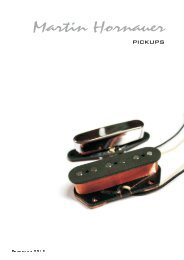
The <strong>PILOT</strong> <strong>150</strong> is an innovative projector with an elegant housing, which is made from high<br />
intensity and heat–resistant complex plastic. <strong>PILOT</strong> <strong>150</strong> compiles to CE norms and standards and<br />
uses international control protocol DMX 512. The projector may also be used as a stand-alone unit,<br />
master/slave synchro mode or controller mode if desired, controlled by sound, and/or automatic<br />
internal programmes, so it is suitable for many different applications.<br />
<strong>PILOT</strong> <strong>150</strong> features 9 dichroic colours, 7 interchangeable rotating gobos, and an independent<br />
adjustable strobe/shutter. It can be setup easily via the touch-switches and digital display screen.<br />
2/14 pilot <strong>150</strong> manual.doc
When unpacking and before disposing of the carton check there is no transportation damage before<br />
using the projector. Should there be any damage caused by transportation, consult your dealer and<br />
do not use the unit.<br />
The projector is for Indoor use only, IP20. Use only in dry locations. Keep this device away from<br />
rain and moisture, excessive heat, humidity and dust. Do not allow contact with water or any other<br />
fluids, or metallic objects.<br />
The projector is only intended for installation, operation and maintenance by qualified personnel.<br />
The projector is not designed or intended to be mounted directly on to inflammable surfaces.<br />
The projector must be installed in a location with adequate ventilation, at least 50cm from adjacent<br />
surfaces. Be sure that no ventilation slots are blocked.<br />
Do not project the beam onto inflammable surfaces, minimum distance is 3m. 3m<br />
Avoid direct exposure to the light from the lamp. The light is harmful to the eye.<br />
Do not attempt to dismantle and/or modify the projector in any way.<br />
Electrical connection must only be carried out by qualified personnel.<br />
Before installation, ensure that the voltage and frequency of power supply match the power<br />
requirements of the projector.<br />
It is essential that each projector is correctly earthed and that electrical installation conforms to all<br />
relevant standards.<br />
Do not connect this device to any dimmer pack.<br />
Make sure that the power-cord is never crimped or damaged by sharp edges. Never let the powercord<br />
come into contact with other cables. Only handle the power-cord by the plug. Never pull out<br />
the plug by tugging the power-cord.<br />
The projector should always be installed with a secondary safety fixing. A safety cord is supplied for<br />
this, it should be attached as shown.<br />
The lamp used in this projector is an HTI <strong>150</strong>W/DX discharge lamp. After being switched off don’t<br />
attempt to restart the projector until lamp has cooled, this will require approx 15 minutes. Switching<br />
the lamp on and off at short intervals will reduce the life of both the lamp and the projector.<br />
Never run the projector without a lamp.<br />
SAFE USAGE OF THE PROJECTOR<br />
There are no user serviceable parts inside the projector, do not open the housing and never<br />
operate the projector with the covers removed.<br />
Always disconnect from the mains, when the device is not in use or before cleaning it or before<br />
attempting any maintenance work.<br />
If you have any questions, don’t hesitate to consult your dealer.<br />
3/14 pilot <strong>150</strong> manual.doc
INSTALLING THE PROJECTOR<br />
The projector should be mounted via its bracket using one M12 bolt. The bracket itself attaches to<br />
the underside of the projector with two (2) M8x25 bolts provided. Always ensure that the projector is<br />
firmly anchored to avoid vibration and slipping whilst operating. Always ensure that the structure to<br />
which you are attaching the projector is secure and is able to support a weight of 11.5Kg for each<br />
<strong>PILOT</strong> <strong>150</strong>. For safety the projector should have a secondary fixing with a safety chain through the<br />
holes on the underside of the unit.<br />
WARNING: The projector should NEVER be lifted or carried by the yoke.<br />
FITTING THE LAMP<br />
Open the lamp access hatch at the rear of the projector by undoing the 2 access screws as shown<br />
above.<br />
Insert an HTI <strong>150</strong>W/DX lamp in the lamp holder. Close the access hatch carefully and retighten the 2<br />
access screws.<br />
NOTE: To optimize light output it will be necessary to adjust the lamp alignment to obtain an even<br />
distribution of light within the beam. The three screws (marked A, B, and C) may be gently turned to<br />
center the lamp within the reflector. The projector should be switched on with the shutter open and<br />
the beam focused to do this, it is also advisable to allow the lamp 5 minutes to come up to full<br />
brightness before starting to align it. Note: the three screws will only need a small adjustment to<br />
centre the lamp, do not try to unscrew them completely. Read the rest of this manual and then<br />
come back to this section to align the lamp.<br />
The HTI series are high pressure lamps with external igniters . Care should always be taken<br />
when handling these lamps. Always read the manufacturers "Instructions for use" enclosed with the<br />
lamp.<br />
4/14 pilot <strong>150</strong> manual.doc
CONTROL CONNECTIONS<br />
Connection between controller and projector and between one projector and another must be made<br />
with 2 core screened cable, with each core having at least a 0.5mm diameter. Connection to and<br />
from the projector is via cannon 3 pin XLR plugs and sockets which are included with the projector.<br />
The XLR's are connected as shown in the table above. Note, care should be taken to ensure that<br />
none of the connections touch the body of the plug or each other. The body of the plug is not<br />
connected in any way. The <strong>PILOT</strong> <strong>150</strong> accepts digital control signals in standard DMX512 (1990)<br />
format.<br />
Connect the controller’s output to the first fixture’s input, and connect the first fixture’s output to the<br />
second fixture’s input. The rest may be deduced by analogy. Eventually connect the last fixture’s<br />
output to a DMX terminator as shown in the figure above.<br />
<strong>PILOT</strong> <strong>150</strong> uses 3-pin XLR plug / socket. If your controller uses 5-pin XLR plug / socket, you should<br />
use a conversion cable from 5-pin to 3-pin as shown bellow.<br />
When a DMX 512 signal is received the LED located near the digital display will illuminate green.<br />
When not receiving a DMX signal the green and red LEDs will be off, and if the green LED flashes,<br />
it means that the DMX signal is not correct.<br />
DMX TERMINATOR<br />
At the last fixture in the chain, the DMX output has to be connected with a DMX terminator. This<br />
prevents electrical noise from disturbing and corrupting the DMX control signals.<br />
The DMX terminator is simply an XLR connector with a 120Ω (ohm) resistor connected across pins<br />
2 and 3, which is then plugged into the output socket on the last projector in the chain. The<br />
connections are illustrated below.<br />
5/14 pilot <strong>150</strong> manual.doc
To browse through the various Setup Options, press the FUNC button consecutively. There are 6<br />
Option codes (1~6), and each code has a specific function. The functions provided are listed in the<br />
following table.<br />
CODE CHOICE FUNCTION<br />
1 Y Tilt inversion enable-Tilt is inverted<br />
1 N Tilt inversion disable-Tilt is normal<br />
2 Y Pan inversion enable-Pan is inverted<br />
2 N Pan inversion disable-Pan is normal<br />
3 Y Sound control (effect 1) enable<br />
3 N Sound control (effect 1) disable<br />
3<br />
4<br />
Y<br />
Y<br />
Sound control (effect 2) enable<br />
3<br />
4<br />
N<br />
Y or N<br />
Sound control (effect 2) disable<br />
5 Y Automatic programmes (effect 1) enable<br />
5 N Automatic programmes (effect 1) disable<br />
4<br />
5<br />
Y<br />
Y<br />
Automatic programmes (effect 2) enable<br />
4<br />
5<br />
N<br />
Y or N<br />
Automatic programmes (effect 2) disable<br />
6 Y 16bit Pan/Tilt movement resolution enable<br />
6 N 16bit Pan/Tilt movement resolution disable<br />
Once you have selected the desired operation code, press the key UP or DOWN to select either “n”<br />
(means OFF) or “y “ (means ON). n = NO, y = YES.<br />
Press the key ENTER to save the selected function and configuration. If the display is showing “y”,<br />
then the setting has been enabled. In the same way, if it was showing “n” when you pressed<br />
ENTER the option has been disabled.<br />
The Red LED will flash during this operation.<br />
Each <strong>PILOT</strong> <strong>150</strong> must be given a DMX start address so that the correct projector responds to the<br />
correct control signals. This DMX start address is the channel number from which the projector<br />
starts to “listen” to the digital control information being sent out from the controller. The <strong>PILOT</strong> <strong>150</strong><br />
has 8 channels, so set the No. 1 projector’s address 001, No. 2 projector’s address 009, No. 3<br />
projector’s address 017, No. 4 projector’s address 025, and so on.<br />
The display shows the DMX start address after the projector is switched on (if you have already set<br />
the DMX start address and saved it, the screen will display the last setting).<br />
TO SET THE DMX START ADDRESS<br />
Press the UP or DOWN buttons and the display will show the DMX start address.<br />
Confirm your choice by pressing the ENTER button, this will save and set the DMX start address.<br />
The display will show the latest setting each time the projector is powered up.<br />
To control the projector with a DMX controller the DMX start address must be set.<br />
Ensure that none of the Stand-Alone options are set or they will interfere with correct DMX<br />
operation.<br />
SETUP OPTIONS – PROJECTOR CONFIGURATION<br />
DMX START ADDRESS<br />
7/14 pilot <strong>150</strong> manual.doc
STAND – ALONE MODE<br />
To operate the projector without connecting a controller, enable a combination of setup options 3, 4<br />
and 5, the projector will run in Stand-Alone mode with or without sound activation depending on the<br />
options that have been selected. See the section on “Setup Options – Projector Configuration” for<br />
full details of the available combinations.<br />
MASTER / SLAVE SYNCHRO MODE<br />
Without using a controller, many projectors can run synchronously in the Master/Slave mode by<br />
linking them with each other. Select one projector as the master with setting the DMX start address<br />
at random. Regard the other projectors as the slaves setting all DMX start address “001”.<br />
Connect the master’s output to the first slave’s input, and connect the first slave’s output to the<br />
second slave’s input. The rest may be deduced by analogy. Eventually connect the last slave’s<br />
output to a DMX terminator as shown in the figure below.<br />
CHANGING THE GOBOS<br />
Carefully lift off the lower cover by undoing the 4 screws. (Note: the lower cover has an obvious<br />
protrusion on the surface, which is different from the upper cover.)<br />
Using a small screwdriver remove the gobo retaining spring.<br />
Insert the gobo (or a glass gobo) into position, and then insert the retaining spring.<br />
Mount the lower cover and tighten the 4 screws again.<br />
8/14 pilot <strong>150</strong> manual.doc
If the projector’s lens becomes damaged or broken it should be replaced. If the lamp becomes<br />
damaged or deformed in any way it must be replaced. If the light from the lamp appears dim this<br />
would normally indicate that it is reaching the end of its life and it should be changed at once, old<br />
lamps run to the extremity of their life can explode. If the projector does not function, check the<br />
fuses on the power socket of the projector, they should only be replaced by fuses of the same<br />
specified value 6.3A/250V. On the main PCB inside the projector there is also a fuse rated 4A/250V.<br />
Should these be damaged call a qualified technician before replacement. The projector has thermal<br />
protection device that will switch off the projector in case of overheating, should either of these<br />
operate, check that the fans are not blocked, and if they are dirty clean them before switching on<br />
the projector again. Check that the fans are operational, if not call a qualified technician.<br />
Any maintenance work should only be carried out by qualified technicians.<br />
To ensure the reliability of the projector it should be kept clean. It is recommended that the fans<br />
should be cleaned every 15 days. The lens and dichroic colour filters should also be regularly<br />
cleaned to maintain an optimum light output. Do NOT use any type of solvent on dichroic colour<br />
filters.<br />
Cleaning frequency depends on the environment in which the fixture operates: damp, smoke or<br />
particularly dirty surroundings can cause greater accumulation of dirt on the unit’s optics. A soft<br />
cloth and typical glass cleaning products should be used in cleaning. It is recommended to clean<br />
the external optics at least once every 20 days and clean the internal optics at least once every 30 /<br />
60 days.<br />
Do not use any organic solvent, e.g. alcohol, to clean the reflector mirror, dichroic color<br />
filters or housing of the projector.<br />
To ensure the continued smooth rotation of the rotating gobos it is recommended that the wheel is<br />
lubricated periodically, preferably every two months. Use only high working temperature low<br />
viscosity oil, a syringe with a fine needle is the easiest way to introduce the oil to the bearings<br />
around each gobo. Do not over lubricate as this will cause spillage when the wheel rotates.<br />
PROBLEM POSSIBLE CAUSE ACTION<br />
The projector doesn’t<br />
switch on<br />
MAINTENANCE<br />
KEEPING THE PROJECTOR CLEAN<br />
LUBRICATION<br />
TROUBLESHOOTING<br />
-The power supply is not<br />
present<br />
-The lamp is not working<br />
Check the fuse on the power<br />
socket.<br />
The lamp comes on but the -Wrong DMX configuration<br />
Replace the lamp.<br />
Make sure that the projector is<br />
projector doesn’t respond and/or start address<br />
correctly configurated.<br />
to the controller<br />
- Defective DMX cable Replace or repair the DMX cable.<br />
The projector only -The fan has failed Make sure the fan is working and<br />
functions intermittently<br />
not dirty.<br />
Defective projection -The lens is broken<br />
Check the lenses are not broken.<br />
-Dust or grease on lenses Remove dust or grease from the<br />
lenses.<br />
The projected image -Installation of the lamp is not Make sure the lamp is installed<br />
appears to have a halo correct<br />
correctly.<br />
-Dust or grease<br />
Carefully clean the optical group<br />
contamination on the optics. lenses and the projector<br />
components.<br />
The beam appears dim -Dust or grease<br />
contamination on the optics.<br />
Check the optics are clean.<br />
-The lamp is at the end of its Replace with a new lamp of the<br />
life<br />
specified type and rating.<br />
9/14 pilot <strong>150</strong> manual.doc
VOLTAGES: 100/120/200/220/230/240V AC, 50Hz or 60Hz<br />
POWER CONSUMPTION:<br />
280W @ 220V<br />
LAMP: Type : HTI <strong>150</strong>W/DX discharge lamp<br />
Colour Temperature: 6500ºK<br />
Socket: GY9.5<br />
Manufacturers Rated Lamp Life: 750 Hours<br />
COLOURS:<br />
9 Dichroic colours plus white<br />
GOBOS:<br />
7 interchangeable, rotating gobos,<br />
with 4 extra supplied as standard<br />
Gobo diameter: 26.9mm<br />
Gobo image diameter: 22mm<br />
SHUTTER/STROBE:<br />
Shutter for blackout and strobe 1 – 7 F.P.S.<br />
HEAD MOVEMENT:<br />
Pan 370º Tilt 265º<br />
CONTROL:<br />
DMX512: 6 Channels plus 2 for Hi Res. Pan and Tilt<br />
Stand-Alone Automatic mode and Sound Activation<br />
RUNNING MODE:<br />
Stand-Alone mode, Master-slave mode and Controller mode<br />
MOTORS:<br />
6 Stepper motors<br />
HOUSING:<br />
Metal and composite plastic (IP20)<br />
WEIGHT:<br />
12Kg<br />
PACKED WEIGHT:<br />
13.5Kg<br />
PACKED DIMENSIONS:<br />
380mm LONG x 340mm WIDE x 470mm HIGH<br />
DIMENSIONS<br />
TECHNICAL DATA<br />
10/14 pilot <strong>150</strong> manual.doc
LIGHT OUTPUT<br />
ELECTRICAL DIAGRAM<br />
11/14 pilot <strong>150</strong> manual.doc
COMPONENT ORDER CODES<br />
NO NAME PART NO. REMARK<br />
040020035 240V/50Hz<br />
1 TRANSFORMER<br />
040020037<br />
100V/200V/230V<br />
50/60Hz<br />
040020033<br />
100V/120V/220V<br />
50/60Hz<br />
2 CAPACITOR 140010011 20µF/AC370V<br />
3 BALLAST<br />
040070027<br />
040070022<br />
240V/50Hz<br />
220V-230V/50-60Hz<br />
4 THERMOSTAT 190010066 75ºC /10A<br />
040090017 240V/50Hz<br />
5 IGNITOR<br />
040090014 230V/50Hz<br />
040090018 200V/60Hz<br />
6 LAMP 100050014 HTI <strong>150</strong>W<br />
7 TOUCH SWITCH 191010028<br />
8 FAN IN BASE 030069005 DC24V/2.4W<br />
9 FAN IN HEAD 030069006 DC24V/2.6W<br />
MOTOR 1 (GOBO-WHEEL) MOTOR 030040070 16HY1405-01NL<br />
MOTOR 2 (GOBO ROTATION) MOTOR 030040057 16HY7403-01L<br />
MOTOR 3 (COLOUR-WHEEL) MOTOR 030040057 16HY7403-01L<br />
MOTOR 4 (SHUTTER) MOTOR 030040072 16HY7403-04L<br />
MOTOR 5 (PAN) MOTOR 030040054 17HS3005L<br />
MOTOR 6 (TILT) MOTOR 030040042 17HS1013-04L<br />
A1~A4<br />
A5<br />
IC<br />
IC<br />
170170003<br />
170110004<br />
DRIVER CHIPS<br />
A6 IC 170050001 ARITH–AMPLIFIER CHIP<br />
A7 IC 170110004 DRIVER CHIP<br />
B2, B2 IC 170170037 D/A CONVERSION CHIP<br />
B3 IC 170040014 TTL LOGIC CHIP<br />
B4~B7 IC 170170037 D/A CONVERSION CHIP<br />
B8, B9 IC 170040014 TTL LOGIC CHIP<br />
C1 IC 170170039 STABLE VOLTAGE CHIP<br />
C2 IC 170050001 ARITH–AMPLIFIER CHIP<br />
C3 IC 170170012 BUS CHIP<br />
C4 IC 170040033 EEPROM CHIP<br />
D1 IC 230040109 MICROPROCESSOR<br />
E1 IC 170040035 RESET CHIP<br />
NOT<br />
SHOWN PAN DRIVE BELT 290151202 101MXL BELT (126 TEETH)<br />
NOT<br />
SHOWN TILT DRIVE BELT 290151208 168MXL BELT (210 TEETH)<br />
NOTE: You may order all parts of the <strong>PILOT</strong> <strong>150</strong> besides those in the table listed above. When<br />
ordering please state the exact name and part number, if you know it or can find it in the table<br />
above, if you cannot find the name and part number above please give a full and clear<br />
description of the part and where it is located in the projector. Repairs must be carried out by a<br />
qualified technician.<br />
12/14 pilot <strong>150</strong> manual.doc
13/14 pilot <strong>150</strong> manual.doc
PR LIGHTING LTD.<br />
No. 571 Yingbin Road, Dashi, Panyu, Guangzhou ,China<br />
Post-Code: 511430<br />
TEL: +086-020-8478 1888<br />
FAX: +086-020-8478 6023<br />
P/N: 321010042<br />
Last Revision: 28:06:2004<br />
14/14 pilot <strong>150</strong> manual.doc