User Manual 6009-33 - Livewire Connections Ltd
User Manual 6009-33 - Livewire Connections Ltd
User Manual 6009-33 - Livewire Connections Ltd

You also want an ePaper? Increase the reach of your titles
YUMPU automatically turns print PDFs into web optimized ePapers that Google loves.
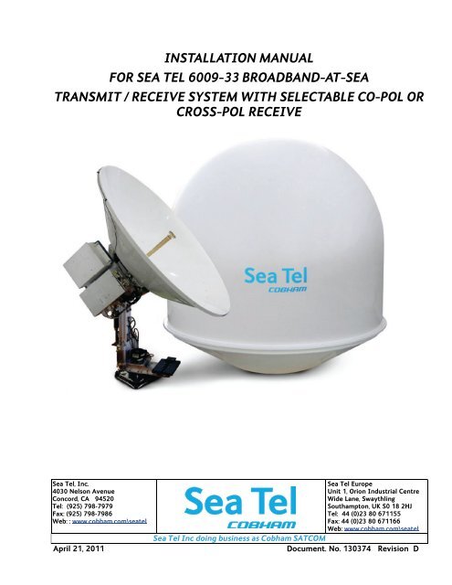
INSTALLATION MANUAL<br />
FOR SEA TEL <strong>6009</strong>-<strong>33</strong> BROADBAND-AT-SEA<br />
TRANSMIT / RECEIVE SYSTEM WITH SELECTABLE CO-POL OR<br />
CROSS-POL RECEIVE<br />
Sea Tel, Inc.<br />
4030 Nelson Avenue<br />
Concord, CA 94520<br />
Tel: (925) 798-7979<br />
Fax: (925) 798-7986<br />
Web: : www.cobham.com\seatel<br />
April 21, 2011<br />
Sea Tel Europe<br />
Unit 1, Orion Industrial Centre<br />
Wide Lane, Swaythling<br />
Southampton, UK S0 18 2HJ<br />
Tel: 44 (0)23 80 671155<br />
Fax: 44 (0)23 80 671166<br />
Web: www.cobham.com\seatel<br />
Sea Tel Inc doing business as Cobham SATCOM<br />
Document. No. 130374 Revision D
These commodities, technology or software were exported from the United<br />
States in accordance with the Export Administration Regulations. Diversion<br />
contrary to U.S. law is prohibited.<br />
Sea Tel Marine Stabilized Antenna systems are manufactured in the United<br />
States of America.<br />
Sea Tel is an ISO 9001:2008 registered company.<br />
Certificate Number 13690 issued March 14, 2011.<br />
R&TTE<br />
CE<br />
The Series 09 Family of Marine Stabilized Antenna Pedestals with DAC-2202 or DAC-2302<br />
Antenna Control Unit complies with the requirements of directive 1999/5/EC of the European<br />
Parliament and of the Council of 9 March 1999 on Radio equipment and Telecommunication<br />
Terminal Equipment. A copy of the R&TTE Declaration of Conformity for this equipment is<br />
contained in this manual.<br />
The Sea Tel Series 09 & 10 antennas will meet the off-axis EIRP spectral density envelope set forth in FCC 47<br />
C.F.R. § 25.222(a)(1) when the input power density limitations, listed in our FCC Declaration, are met..<br />
These antenna systems also contain FCC compliant supervisory software to continuously monitor the pedestal<br />
pointing accuracy and use it to control the “Transmit Mute” function of the satellite modem to satisfy the<br />
provisions of FCC 47 C.F.R. § 25.222(a)(l)(iii).<br />
Copyright Notice<br />
All Rights Reserved. The information contained in this document is proprietary to Sea Tel, Inc.. This document<br />
may not be reproduced or distributed in any form without prior consent of Sea Tel, Inc. The information in<br />
this document is subject to change without notice. Copyright © 2009 Sea Tel, Inc is doing business as<br />
Cobham SATCOM.<br />
This document has been registered with the U.S. Copyright Office.<br />
Revision History<br />
REV ECO# Date Description By<br />
X2 N/A July 10, 2009 PRELIMINARY Release. MDN<br />
X5 N/A September 9, 2009 PRELIMINARY 2 nd Release. MDN<br />
A N/A September 30, 2009 Production Release MDN<br />
B 6990 December 7, 2009 Update text to include GSR2 software functions MDN<br />
C N/A July 9, 2010 Update text to include GSR3 software functions MDN<br />
C1 7450 August 30, 2010 Update text to add MDE software update instructions MDN<br />
D N/A April 20, 2011 Removed Diagnostic Software AND Setup - CommIF Chapter ,added<br />
Functional Testing AND Stowing the Antenna chapters, update PCU<br />
configuration and drawings.<br />
MDN<br />
ii
Table of Contents<br />
<strong>6009</strong>-<strong>33</strong> Installation <strong>Manual</strong><br />
1. 09 SERIES SYSTEM CONFIGURATION(S) ................................................................................................................................... 1-1<br />
1.1. SERIES 09 BASIC SYSTEM INFORMATION ................................................................................................................................................ 1-1<br />
1.2. SYSTEM CABLES ............................................................................................................................................................................................. 1-1<br />
1.3. OTHER INPUTS TO THE SYSTEM .................................................................................................................................................................. 1-1<br />
1.4. SIMPLIFIED BLOCK DIAGRAM OF A SERIES 09 SYSTEM .......................................................................................................................... 1-1<br />
1.5. DUAL ANTENNA CONFIGURATION ............................................................................................................................................................. 1-2<br />
1.6. DUAL ANTENNA ARBITRATOR ..................................................................................................................................................................... 1-3<br />
1.7. OPEN ANTENNA-MODEM INTERFACE PROTOCOL (OPENAMIP) SPECIFICATION: ........................................................................ 1-3<br />
1.7.1. Overview: ........................................................................................................................................................................................ 1-3<br />
1.7.2. Interface requirements: ......................................................................................................................................................... 1-4<br />
1.7.3. Utilized OpenAMIP Commands: ........................................................................................................................................ 1-4<br />
2. SITE SURVEY .................................................................................................................................................................................................. 2-1<br />
2.1. SITE SELECTION ABOARD SHIP ................................................................................................................................................................... 2-1<br />
2.2. ANTENNA SHADOWING (BLOCKAGE) AND RF INTERFERENCE .............................................................................................................. 2-1<br />
2.3. MOUNTING FOUNDATION ........................................................................................................................................................................... 2-2<br />
2.3.1. Mounting on Deck or Deckhouse ...................................................................................................................................... 2-2<br />
2.3.2. ADE Mounting Considerations ........................................................................................................................................... 2-2<br />
2.3.3. Sizing of the support pedestal ............................................................................................................................................ 2-2<br />
2.4. MOUNTING HEIGHT ...................................................................................................................................................................................... 2-3<br />
2.5. MAST CONFIGURATIONS ............................................................................................................................................................................. 2-3<br />
2.5.1. Vertical Masts .............................................................................................................................................................................. 2-4<br />
2.5.2. Raked Masts .................................................................................................................................................................................. 2-4<br />
2.5.3. Girder Masts ................................................................................................................................................................................. 2-4<br />
2.5.4. Truss Mast ..................................................................................................................................................................................... 2-5<br />
2.6. SAFE ACCESS TO THE ADE .......................................................................................................................................................................... 2-5<br />
2.7. BELOW DECKS EQUIPMENT LOCATION ..................................................................................................................................................... 2-5<br />
2.8. CABLES ............................................................................................................................................................................................................. 2-5<br />
2.8.1. ADE/BDE Coaxial Cables ........................................................................................................................................................ 2-6<br />
2.8.2. Antenna Power Cable .............................................................................................................................................................. 2-6<br />
2.8.3. Air Conditioner Power Cable ............................................................................................................................................... 2-6<br />
2.8.4. ACU Power Cable/outlet ........................................................................................................................................................ 2-6<br />
2.8.5. Gyro Compass Cable ................................................................................................................................................................ 2-6<br />
2.9. GROUNDING .................................................................................................................................................................................................... 2-6<br />
3. INSTALLATION ............................................................................................................................................................................................. 3-1<br />
3.1. UNPACKING AND INSPECTION .................................................................................................................................................................... 3-1<br />
3.2. ASSEMBLY NOTES AND WARNINGS ........................................................................................................................................................... 3-1<br />
3.3. INSTALLING THE ADE ................................................................................................................................................................................... 3-2<br />
3.3.1. Prepare the 50”, 60”, 66” or 76” Radome Assembly ................................................................................................ 3-2<br />
3.3.2. Install 76” Radome to mounting deck. ........................................................................................................................... 3-3<br />
3.3.3. Preparing & Installing the Single Piece 81” Radome Assembly ........................................................................ 3-4<br />
3.4. REMOVING THE SHIPPING/STOW RESTRAINTS PRIOR TO POWER-UP .............................................................................................. 3-4<br />
3.4.1. Removing the AZ Shipping/Stow Restraint .................................................................................................................. 3-4<br />
3.4.2. Removing the EL Shipping/Stow Restraint ................................................................................................................... 3-5<br />
3.4.3. Removing the CL Shipping/Stow Restraint ................................................................................................................... 3-7<br />
3.5. CABLE INSTALLATION ................................................................................................................................................................................... 3-7<br />
3.5.1. Shipboard Cable Installation ............................................................................................................................................... 3-7<br />
3.5.2. Cable Terminations In The 81 inch Radome ............................................................................................................... 3-7<br />
3.6. INSTALLING THE BELOW DECKS EQUIPMENT. .......................................................................................................................................... 3-8<br />
v
<strong>6009</strong>-<strong>33</strong> Installation <strong>Manual</strong> Table of Contents<br />
3.6.1. General Cautions & Warnings ............................................................................................................................................. 3-8<br />
3.6.2. Preparing BDE Location ......................................................................................................................................................... 3-8<br />
3.6.3. System Configuration ............................................................................................................................................................. 3-9<br />
3.6.4. Installing the Below Deck Equipment ............................................................................................................................ 3-9<br />
3.7. CONNECTING THE BELOW DECKS EQUIPMENT ........................................................................................................................................ 3-9<br />
3.7.1. Connecting the ADE AC Power Cable ............................................................................................................................ 3-9<br />
3.7.2. Connecting the BDE AC Power Cables .......................................................................................................................... 3-9<br />
3.7.3. Connecting the ADE IF Coaxes ...................................................................................................................................... 3-10<br />
3.7.4. Connect the Modem TXIF Coax .................................................................................................................................... 3-10<br />
3.7.5. Antenna Control Unit <strong>Connections</strong> .............................................................................................................................. 3-10<br />
3.7.6. 1<strong>33</strong>BURadio Control Serial Cable .................................................................................................................................. 3-10<br />
3.7.7. Terminal Mounting Strip (TMS) <strong>Connections</strong> ......................................................................................................... 3-10<br />
3.7.8. Other BDE connections ...................................................................................................................................................... 3-13<br />
3.8. FINAL CHECKS.............................................................................................................................................................................................. 3-13<br />
3.8.1. Visual/Electrical inspection ............................................................................................................................................... 3-13<br />
3.8.2. Electrical - Double check wiring connections ......................................................................................................... 3-13<br />
3.9. POWER-UP ................................................................................................................................................................................................... 3-13<br />
3.10. 61BANTENNA MAINTENANCE ................................................................................................................................................................ 3-14<br />
3.10.1. Balancing the Antenna ........................................................................................................................................................ 3-14<br />
3.10.2. Fine Balance and Monitoring Motor Drive Torque .............................................................................................. 3-14<br />
4. BASIC SETUP OF THE ACU .................................................................................................................................................................. 4-1<br />
4.1. OPERATOR SETTINGS ..................................................................................................................................................................................... 4-1<br />
4.2. SETUP PARAMETER DISPLAY AND ENTRY MENUS. .................................................................................................................................. 4-1<br />
4.3. DEFAULT SETUP PARAMETERS FOR YOUR ANTENNA ............................................................................................................................... 4-1<br />
4.4. SAVE NEW PARAMETERS ...................................................................................................................................................................... 4-2<br />
5. SETUP – SHIPS GYRO COMPASS ...................................................................................................................................................... 5-1<br />
5.1. GYRO TYPE ................................................................................................................................................................................................... 5-1<br />
5.2. UPDATING THE GYRO TYPE PARAMETER ................................................................................................................................................ 5-1<br />
5.3. IF THERE IS NO SHIPS GYRO COMPASS .................................................................................................................................................... 5-1<br />
6. SETUP – TRACKING RECEIVER - VSAT ........................................................................................................................................ 6-1<br />
6.1. DETERMINING THE IF TRACKING FREQUENCY (MHZ)........................................................................................................................... 6-1<br />
6.2. KHZ ................................................................................................................................................................................................................... 6-1<br />
6.3. FEC ................................................................................................................................................................................................................... 6-1<br />
6.3.1. L-Band SCPC Receiver ............................................................................................................................................................. 6-1<br />
6.4. TONE ................................................................................................................................................................................................................. 6-1<br />
6.4.1. VSAT Application ....................................................................................................................................................................... 6-1<br />
6.5. VOLT ................................................................................................................................................................................................................. 6-2<br />
6.5.1. VSAT Application ....................................................................................................................................................................... 6-2<br />
6.6. SAT SKEW ..................................................................................................................................................................................................... 6-2<br />
6.7. NID .................................................................................................................................................................................................................. 6-2<br />
7. SETUP – BAND SELECTION .................................................................................................................................................................. 7-1<br />
7.4. CROSS-POL ONLY QUAD-BAND LNB ......................................................................................................................................................... 7-2<br />
7.8. CROSS-POL AND CO-POL QUAD-BAND LNBS ....................................................................................................................................... 7-3<br />
8. SETUP – TARGETING ................................................................................................................................................................................ 8-1<br />
8.1. AUTO TRIM ................................................................................................................................................................................................. 8-1<br />
8.2. MANUALLY OPTIMIZING TARGETING ........................................................................................................................................................ 8-1<br />
8.3. EL TRIM .......................................................................................................................................................................................................... 8-2<br />
8.4. AZ TRIM ........................................................................................................................................................................................................ 8-2<br />
vi
Table of Contents<br />
<strong>6009</strong>-<strong>33</strong> Installation <strong>Manual</strong><br />
9. SETUP – HOME FLAG OFFSET ............................................................................................................................................................. 9-1<br />
9.1. ELECTRONIC CALIBRATION OF RELATIVE ANTENNA POSITION (HOME FLAG OFFSET) ................................................................... 9-1<br />
9.1.1. You Found a Large AZ TRIM value: .................................................................................................................................. 9-1<br />
9.1.2. You Observe “Home” Pointing is LEFT of the Bow-line: ......................................................................................... 9-2<br />
9.1.3. You Observe “Home” Pointing is RIGHT of the Bow-line: ..................................................................................... 9-2<br />
9.1.4. To Enter the HFO value in the DAC_2202: ................................................................................................................... 9-3<br />
9.2. MECHANICAL CALIBRATION OF RELATIVE ANTENNA POSITION (HOME FLAG OFFSET) ................................................................. 9-4<br />
10. SETUP – SEARCHING ............................................................................................................................................................................. 10-1<br />
10.1. SEARCHING OPERATION ............................................................................................................................................................................. 10-1<br />
10.1.1. Default Standard (Box) Search Pattern ....................................................................................................................... 10-1<br />
10.1.2. Inclined Orbit Search Pattern .......................................................................................................................................... 10-2<br />
10.1.3. No Gyro Search Pattern ...................................................................................................................................................... 10-3<br />
10.2. CHANGING THE SEARCH PARAMETERS .................................................................................................................................................... 10-4<br />
10.2.1. AUTO THRES ............................................................................................................................................................................. 10-4<br />
10.2.2. EL STEP SIZE ............................................................................................................................................................................ 10-4<br />
10.2.3. AZ STEP SIZE ........................................................................................................................................................................... 10-4<br />
10.2.4. STEP INTEGRAL ....................................................................................................................................................................... 10-4<br />
10.2.5. SEARCH INC .............................................................................................................................................................................. 10-5<br />
10.2.6. SEARCH LIMIT ......................................................................................................................................................................... 10-5<br />
10.2.7. SEARCH DELAY ........................................................................................................................................................................ 10-5<br />
10.2.8. SWEEP INC ................................................................................................................................................................................ 10-5<br />
10.3. SAVE NEW PARAMETERS ................................................................................................................................................................... 10-5<br />
11. SETUP – BLOCKAGE & RF RADIATION HAZARD ZONES .............................................................................................. 11-1<br />
11.1. RADIATION HAZARD AND BLOCKAGE MAPPING (AZ LIMIT PARAMETERS) ................................................................................... 11-1<br />
11.2. SAVE NEW PARAMETERS ................................................................................................................................................................... 11-4<br />
12. SETUP – MODEM CONNECTIONS, SETUP AND TEST ..................................................................................................... 12-1<br />
12.1. IDIRECT MODEMS ....................................................................................................................................................................................... 12-1<br />
12.2. COMTECH MODEMS .................................................................................................................................................................................... 12-1<br />
12.3. HUGHES MODEMS ....................................................................................................................................................................................... 12-1<br />
12.4. CONNECTIONS (ACU TO SATELLITE MODEM) ...................................................................................................................................... 12-2<br />
12.4.1. iDirect Modems ....................................................................................................................................................................... 12-2<br />
12.4.2. Comtech Modems .................................................................................................................................................................. 12-2<br />
12.4.3. Hughes Modems ..................................................................................................................................................................... 12-2<br />
12.5. SYSTEM TYPE PARAMETER ..................................................................................................................................................................... 12-2<br />
12.6. BLOCKAGE SIMULATION TEST................................................................................................................................................................... 12-3<br />
12.7. TESTING THE SATELLITE MODEM LOCK (NETWORK ID) INPUT IN THE ACU ................................................................................. 12-4<br />
12.8. SAVE NEW PARAMETERS ................................................................................................................................................................... 12-5<br />
13. SETUP – OPTIMIZING POLARITY & CROSS-POL ISOLATION ................................................................................... 13-1<br />
13.1. SAT SKEW SETTING ..................................................................................................................................................................................... 13-1<br />
13.2. POLARITY ANGLE (POLANG) PARAMETERS ........................................................................................................................................... 13-1<br />
13.3. OPTIMIZING AUTO-POLARIZATION ON RECEIVE SIGNAL .................................................................................................................... 13-1<br />
13.4. OPTIMIZING AUTO-POLARIZATION CROSS-POL ISOLATION .............................................................................................................. 13-2<br />
14. SETUP – OTHER PARAMETERS ....................................................................................................................................................... 14-1<br />
14.1. SETUP PARAMETER DISPLAY AND ENTRY MENUS. ................................................................................................................................ 14-1<br />
14.2. 5V OFFSET (MAY NOT BE IN YOUR SOFTWARE) ................................................................................................................................. 14-1<br />
14.3. 5V SCALE (MAY NOT BE IN YOUR SOFTWARE) .................................................................................................................................... 14-1<br />
14.4. REMOTE COMMAND ............................................................................................................................................................................ 14-1<br />
14.5. REMOTE MONITOR ............................................................................................................................................................................... 14-1<br />
vii
<strong>6009</strong>-<strong>33</strong> Installation <strong>Manual</strong> Table of Contents<br />
14.6. TO DISABLE/ENABLE DISHSCAN .............................................................................................................................................................. 14-1<br />
14.7. SATELLITE REFERENCE MODE ................................................................................................................................................................... 14-2<br />
14.8. REMOTE PARAMETERS ....................................................................................................................................................................... 14-2<br />
15. FUNCTIONAL TESTING ....................................................................................................................................................................... 15-1<br />
15.1. ACU / ANTENNA SYSTEM CHECK ........................................................................................................................................................... 15-1<br />
15.2. LATITUDE/LONGITUDE AUTO-UPDATE CHECK ..................................................................................................................................... 15-1<br />
15.3. HEADING FOLLOWING ................................................................................................................................................................................ 15-1<br />
15.4. BLOCKAGE SIMULATION TEST .................................................................................................................................................................. 15-1<br />
15.5. FOUR QUADRANT TEST TRACKING .......................................................................................................................................................... 15-2<br />
15.6. BLOCKAGE SIMULATION TEST .................................................................................................................................................................. 15-3<br />
15.7. TEST BROADBAND OPERATION ................................................................................................................................................................ 15-4<br />
15.8. TEST VOICE OVER IP (VOIP) OPERATION ............................................................................................................................................ 15-4<br />
16. INSTALLATION TROUBLESHOOTING ........................................................................................................................................ 16-1<br />
16.1. WARRANTY INFORMATION ....................................................................................................................................................................... 16-1<br />
16.2. TROUBLESHOOTING THE ACU ................................................................................................................................................................. 16-1<br />
16.2.1. ACU display is blank .............................................................................................................................................................. 16-2<br />
16.2.2. ACU Status displays "REMOTE NOT RESPONDING" ............................................................................................ 16-2<br />
16.3. TROUBLESHOOTING SHIPS GYRO COMPASS PROBLEMS ...................................................................................................................... 16-2<br />
16.3.1. STEP-BY-STEP ........................................................................................................................................................................... 16-2<br />
16.3.2. 1:1 SYNCHRO ............................................................................................................................................................................ 16-2<br />
16.3.3. 360:1 Synchro .......................................................................................................................................................................... 16-3<br />
17.1. INSTALLING THE STOW RESTRAINTS ....................................................................................................................................................... 16-1<br />
17.1.1. Installing the AZ Shipping/Stow Restraint ............................................................................................................... 16-1<br />
17.1.2. Installing the EL Shipping/Stow Restraint ................................................................................................................. 16-2<br />
17.1.3. Installing the CL Shipping/Stow Restraint ................................................................................................................ 16-4<br />
17.2. REMOVING THE SHIPPING/STOW RESTRAINTS PRIOR TO POWER-UP............................................................................................ 16-4<br />
17.2.1. Removing the AZ Shipping/Stow Restraint .............................................................................................................. 16-4<br />
17.2.2. Removing the EL Shipping/Stow Restraint ................................................................................................................ 16-5<br />
17.2.3. Removing the CL Shipping/Stow Restraint ............................................................................................................... 16-7<br />
18. DAC-2202 TECHNICAL SPECIFICATIONS .............................................................................................................................. 18-1<br />
18.1. DAC-2202 ANTENNA CONTROL UNIT ................................................................................................................................................. 18-1<br />
18.1.1. General......................................................................................................................................................................................... 18-1<br />
18.1.2. Front Panel ................................................................................................................................................................................ 18-1<br />
18.1.3. Rear Panel .................................................................................................................................................................................. 18-1<br />
18.1.4. J4A “Antenna” Pedestal M&C Interface ..................................................................................................................... 18-1<br />
18.1.5. J4B “Antenna” Pedestal M&C Interface ..................................................................................................................... 18-2<br />
18.1.6. J3 “M&C” Aux Serial Interface ......................................................................................................................................... 18-2<br />
18.1.7. J2 “NMEA A” Interface ........................................................................................................................................................ 18-2<br />
18.1.8. J2 “NMEA B” Interface ......................................................................................................................................................... 18-2<br />
18.1.9. Ethernet ...................................................................................................................................................................................... 18-2<br />
18.1.10. DVB Compliant Tracking Receiver ................................................................................................................................. 18-3<br />
18.1.11. L-Band SCPC Narrow Band Tracking Receiver ........................................................................................................ 18-3<br />
18.1.12. Narrow Band SCPC receiver (DAC-2302 ONLY): .................................................................................................... 18-3<br />
18.2. TERMINAL MOUNTING STRIP ................................................................................................................................................................... 18-3<br />
18.2.1. Synchro Interface: ................................................................................................................................................................. 18-3<br />
18.2.2. SBS Interface............................................................................................................................................................................ 18-4<br />
18.2.3. Control Interface ................................................................................................................................................................... 18-4<br />
18.2.4. NMEA Interface ...................................................................................................................................................................... 18-4<br />
viii
Table of Contents<br />
<strong>6009</strong>-<strong>33</strong> Installation <strong>Manual</strong><br />
18.3. ENVIRONMENTAL CONDITIONS ................................................................................................................................................................ 18-5<br />
18.4. DAC-2202 AC POWER CONSUMPTION................................................................................................................................................ 18-5<br />
18.5. CABLES ........................................................................................................................................................................................................... 18-5<br />
18.5.1. IF Signal Cables ....................................................................................................................................................................... 18-5<br />
18.5.2. SBS/Synchro Gyro Compass Interface Cable (Customer Furnished) ......................................................... 18-5<br />
19. <strong>6009</strong>-<strong>33</strong> TECHNICAL SPECIFICATIONS .................................................................................................................................. 19-1<br />
19.1. ANTENNA ASSEMBLY <strong>6009</strong> ...................................................................................................................................................................... 19-1<br />
19.2. SMW QUAD BAND LNB ........................................................................................................................................................................... 19-1<br />
19.3. TX RADIO PACKAGE ( -<strong>33</strong> SYSTEMS) ..................................................................................................................................................... 19-2<br />
19.4. BUC POWER SUPPLY ................................................................................................................................................................................... 19-2<br />
19.5. MK 2 PEDESTAL CONTROL UNIT (PCU) ............................................................................................................................................... 19-2<br />
19.6. 400 MHZ BASE & PEDESTAL UNLIMITED AZIMUTH MODEMS (3 CHANNEL) ............................................................................... 19-3<br />
19.7. MK 2 MOTOR DRIVER ENCLOSURE (MDE) .......................................................................................................................................... 19-3<br />
19.8. STABILIZED ANTENNA PEDESTAL ASSEMBLY ......................................................................................................................................... 19-4<br />
19.9. RADOME ASSEMBLY, 76” ........................................................................................................................................................................... 19-5<br />
19.10. RADOME ASSEMBLY, 81” ........................................................................................................................................................................... 19-6<br />
19.11. ADE PEDESTAL POWER REQUIREMENTS: ................................................................................................................................................ 19-6<br />
19.12. XX09 ENVIRONMENTAL SPECIFICATIONS ............................................................................................................................................. 19-6<br />
19.12.1. Climatic Conditions ............................................................................................................................................................... 19-6<br />
19.12.2. Chemically Active Substances ......................................................................................................................................... 19-6<br />
19.12.3. Mechanical Conditions ........................................................................................................................................................ 19-7<br />
19.12.4. Transit Conditions .................................................................................................................................................................. 19-7<br />
19.13. BELOW DECKS EQUIPMENT ....................................................................................................................................................................... 19-7<br />
19.13.1. Antenna Control Unit (ACU).............................................................................................................................................. 19-7<br />
19.13.2. Terminal Mounting Strip (TMS) ....................................................................................................................................... 19-7<br />
19.13.3. Satellite Modem ...................................................................................................................................................................... 19-7<br />
19.13.4. Router ........................................................................................................................................................................................... 19-7<br />
19.14. CABLES ........................................................................................................................................................................................................... 19-8<br />
19.14.1. Antenna Control Cable (Provided from ACU to the Base MUX) .................................................................... 19-8<br />
19.14.2. Antenna L-Band IF Coax Cables (Customer Furnished)..................................................................................... 19-8<br />
19.14.3. Multi-conductor Cables (Customer Furnished) ...................................................................................................... 19-8<br />
20. DRAWINGS ................................................................................................................................................................................................... 20-1<br />
20.1. DAC-2202 ANTENNA CONTROL UNIT DRAWINGS ............................................................................................................................ 20-1<br />
20.2. <strong>6009</strong>-<strong>33</strong> KU-BAND MODEL SPECIFIC DRAWINGS ............................................................................................................................. 20-1<br />
20.3. SERIES 09 GENERAL DRAWINGS .............................................................................................................................................................. 20-1<br />
ix
<strong>6009</strong>-<strong>33</strong> Installation <strong>Manual</strong> Table of Contents<br />
This Page Intentionally Left Blank<br />
x
09 Series System Configuration(s) <strong>6009</strong>-<strong>33</strong> Installation <strong>Manual</strong><br />
1. 09 Series System Configuration(s)<br />
The 09 Series Stabilized Antenna system is to be used for Transmit/Receive (TX/RX) satellite communications, it is comprised of<br />
two major groups of equipment. These are the Above Decks Equipment (ADE) and the Below Decks Equipment (BDE). There<br />
will also be interconnecting cables between the ADE & BDE and cables to provide other inputs to the system.<br />
1.1. Series 09 Basic System Information<br />
Series 09 Antennas will be available in 3 dish sizes (Diameter – active area):<br />
• 1.0 M (40 inch)<br />
• 1.2 M (50.0 inch)<br />
• 1.5 M (60 inch)<br />
Each dish size will be available in multiple configurations:<br />
• Variety of BUC manufacturers and power output capabilities<br />
• Variety of BUC/HPA power output capabilities<br />
• Cross-Pol Feed assembly<br />
• Optional Co-Pol diplexer and LNB<br />
• Choice of Single fixed frequency, dual-band, tri-band or Quad-Band LNB(s)<br />
The Series 09 antennas are available in multiple tuned radome sizes:<br />
• 131.3 cm (50 inches) Diameter<br />
• 155 cm (60 inch) Diameter<br />
• 1.76 M (66 inch) Diameter<br />
• 201.59cm (76 inch) Diameter<br />
• 205.23cm (81 inch) Diameter [Air Conditioning available for this radome ONLY]<br />
1.2. System Cables<br />
AC Power & Coaxial cables will be discussed in a separate chapter.<br />
1.3. Other Inputs to the System<br />
Multi-conductor cables from Ships Gyro Compass, GPS, phone, fax and Computer equipment may also be connected<br />
in the system.<br />
1.4. Simplified block diagram of a Series 09 system<br />
Your Series 09 TXRX system consists of two major groups of equipment; an above-decks group and a below-decks<br />
group. Each group is comprised of, but is not limited to, the items listed below. All equipment comprising the Above<br />
Decks is incorporated inside the radome assembly and is integrated into a single operational entity. For inputs, this<br />
system requires only an unobstructed line-of-sight view to the satellite, Gyro Compass input and AC electrical power.<br />
A. Above-Decks Equipment (all shown as the ADE) Group<br />
• Stabilized antenna pedestal<br />
• Antenna Reflector<br />
• Feed Assembly with Cross-Pol LNB<br />
• Co-Pol LNB (xx09-17 & <strong>33</strong> Only<br />
• 8W Ku-Band Solid State Block Up-Converter (BUC)<br />
• Radome Assembly<br />
B. Below-Decks Equipment Group<br />
• Antenna Control Unit<br />
• Terminal Mounting Strip Assembly.<br />
• Base Modem Panel<br />
1-1
<strong>6009</strong>-<strong>33</strong> Installation <strong>Manual</strong> 09 Series System Configuration(s)<br />
• Customer Furnished Equipment - Satellite Modem and other below decks equipment required for the<br />
desired communications purposes (including LAN and VOIP equipment).<br />
• Appropriate Coax, Ethernet, and telephone cables<br />
1.5. Dual Antenna Configuration<br />
Sometimes, due to very large blockage conditions, you may need to install a dual antenna configuration to provide<br />
uninterrupted services. Two full antenna systems are installed and the ACU control outputs are connected to an<br />
arbitrator switch panel which then is connected to the below decks equipment. NOTE: The RXIF from EACH antenna<br />
MUST be connected to the RF IN (J6) on the rear panel of its respective ACU then RFOUT (J7) is connected to the RXIF<br />
input of the Dual Antenna Arbitrator. This connection scheme is required for ACU “A” to be able to control Antenna<br />
“A” (and ONLY Antenna “A”) AND ACU “B” to be able to control Antenna “B” (and ONLY Antenna “B”).<br />
You will program the blockage zone(s) for each of the two antennas (refer to Setup – Blockage Zones). The blockage<br />
output from the ACU is fed to the Terminal Mounting Strip so that the output of each ACU can be connected to the<br />
arbitrator panel to control it. The blockage output is available on SW2 terminal of the Terminal Mounting Strip to<br />
provide a transistor “short” to ground when the antenna is within a blockage zone programmed into the ACU. When<br />
not blocked the SW2 terminal will be an “open”.<br />
When one antenna is blocked, its blockage output will command the arbitrator panel to switch services to the modem<br />
from that antenna to the other antenna. The arbitrator panel provides a logic latch to prevent excess switching when<br />
the ship heading is yawing, therefore, causing if the antenna to be repeatedly blocked – unblocked – blocked.<br />
1-2
09 Series System Configuration(s) <strong>6009</strong>-<strong>33</strong> Installation <strong>Manual</strong><br />
1.6. Dual Antenna Arbitrator<br />
The Dual Antenna Arbitrator panel can pass LNB voltages (and handle 250-400 ma of current) and the RXIF signals on<br />
the RX connections. TXIF, Reference and BUC supply voltage can be passed through this arbitrator panel to the<br />
antenna, but it is not recommended that BUC power be supplied through the dual channel rotary joint of the antenna<br />
(a BUC power supply is provided on all Series 09 Antenna Pedestals).<br />
The blockage (SW2) output, GPS output and Modem lock input from the two terminal mounting strips (antenna “A”<br />
and antenna “B”) are wired through the arbitrator panel to the satellite modem. When antenna “A” is blocked, the<br />
arbitrator PCB will toggle the coax switches so that antenna “B” provides signal to the BDE distribution (multi-switch or<br />
modem). When antenna “A” is no longer blocked the arbitrator will do nothing (because it is a latch circuit). When<br />
antenna “B” is blocked the panel will switch so that antenna “A” is again providing signal the BDE distribution.<br />
To provide a seamless switching transition, refer to the arbitrator installation instructions to balance the TX & RX signal<br />
levels between the two antennas.<br />
1.7. Open Antenna-Modem Interface Protocol (OpenAMIP) Specification:<br />
1.7.1. Overview:<br />
OpenAMIP, an ASCII message based protocol invented and Trademarked by iDirect is a specification for the<br />
interchange of information between an antenna controller and a satellite modem. This protocol allows the<br />
satellite modem to command the ACU (via TCP port 2002) to seek a particular satellite as well as allowing<br />
exchange of information necessary to permit the modem to initiate and maintain communication via the<br />
antenna and the satellite. In general, OpenAMIP is not intended for any purpose except to permit a modem<br />
and the ACU to perform synchronized automatic beam switching. It is NOT a status logging system or a<br />
diagnostic system. In addition, OpenAMIP is intend for a typical installation whereby a specific satellite<br />
modem and Antenna system are properly configured to work together. The protocol does not make specific<br />
provisions for auto-discovery or parameter negotiation. It is still the responsibility of the installer to assure<br />
1-3
<strong>6009</strong>-<strong>33</strong> Installation <strong>Manual</strong> 09 Series System Configuration(s)<br />
the parameters of both the satellite modem (proper option files) and the ACU/PCU (setup parameters) are<br />
actually compatible for the intended satellite(s).<br />
1.7.2.<br />
Interface requirements:<br />
1.7.2.1. Hardware<br />
Sea Tel Antenna Control Units Model DAC2202 or DAC2302.<br />
Any Satellite modem manufacturer that is compatible with OpenAMIP<br />
CAT5 Patch cable<br />
1.7.2.2. Software<br />
Sea Tel model DAC2202:<br />
ACU software version 6.06 or greater<br />
CommIF module software version 1.10f or greater<br />
Sea Tel model DAC2302:<br />
ACU software version 7.06 or greater<br />
CommIF module software version 1.10f or greater<br />
1.7.3. Utilized OpenAMIP Commands:<br />
1.7.3.1. Antenna Commands:<br />
Command Description Example<br />
S f1 f2 f3 Satellite Longitude, 3 parameters:<br />
“S -20.1 1.0 3.5”<br />
Degrees E/W (-value equals West), Latitude Variance (Inclined<br />
Orbit), Sat Skew Offset<br />
P c1 c2 Polarization, 2 parameters:<br />
“P L R”<br />
H,V,L,, or R<br />
H f1 f2 Tracking Frequency: 2 Parameters:<br />
“H 1100.500 0.256”<br />
Center Frequency and Bandwidth in MHz<br />
B f1 f2 Down Conversion Offset: 2 parameters:<br />
“B 10750”<br />
LNB (Receive) Local Oscillator and BUC (TX) L.O.<br />
F Find,<br />
Target satellite using existing S, P,R, and H Parameters<br />
A i Set keep alive in seconds (0 = off) “A 5”<br />
L b1 b2 Modem Lock and free to transmit. 2 parameters:<br />
“L 1 1”<br />
b1 indicates Rx lock and b2 (not utilized) enables/disables Tx<br />
Mute to BUC<br />
W i GPS Update:<br />
“W 300”<br />
Sets GPS Update period in seconds (0 = Off)<br />
I s1 s2 Set modem vendor (s1) and device (s2) 2 parameters: “I iDirect 5100”<br />
1.7.3.2. Modem Commands:<br />
Command Description Example<br />
a i Set keep alive in seconds (0 = off) “a 5”<br />
i s1 s2 Set Antenna Vendor (s1) and device (s2) 2 parameters: “i Sea Tel DAC-2202”<br />
s b1 b2 Antenna Status: 2 parameters:<br />
“s 1 1”<br />
b1 is functional status and b2 is Tx allowed<br />
w b1 f1 f2 t1 Set GPS Position: 4 parameters:<br />
b1 is validity flag, f1 is latitude, f2 is longitude, and t1 is<br />
timestamp<br />
“w 1 38.222 122.123<br />
0”<br />
1-4
Site Survey<br />
<strong>6009</strong>-<strong>33</strong> Installation <strong>Manual</strong><br />
2. Site Survey<br />
The objective of the Site survey is to find the best place to mount the antenna & the below decks equipment, the length and<br />
routing of the cables and any other items or materials that are required to install the system and identify any other issues that<br />
must be resolved before or during the installation. For Naval Engineering level information on this subject, please refer<br />
to Antenna Installation Guideline – Site Arrangement, document number 130040_A available on the Sea Tel<br />
Dealer Support Site.<br />
2.1. Site Selection Aboard Ship<br />
The radome assembly should be installed at a location aboard ship where:<br />
• The antenna has a clear line-of-sight to view as much of the sky (horizon to zenith at all bearings) as is<br />
practical.<br />
• X-Band (3cm) Navigational Radars:<br />
• The ADE should be mounted more than 0.6 meters/2 feet from 2kW (24 km) radars<br />
• The ADE should be mounted more than 2 meters/8 feet from 10kW (72 km) radars<br />
• The ADE should be mounted more than 4 meters/12 feet from 160kW (250km) radars<br />
• S-Band (10cm) Navigational Radars:<br />
• If the ADE is/has C-Band it should be mounted more than 4 meters/12 feet from the S-band Radar.<br />
• The ADE should not be mounted on the same plane as the ship's Radar, so that it is not directly in the Radar<br />
beam path.<br />
• The ADE should be mounted more than 2.5 meters/8 feet from any high power MF/HF antennas (
<strong>6009</strong>-<strong>33</strong> Installation <strong>Manual</strong> Site Survey<br />
2.3. Mounting Foundation<br />
2.3.1. Mounting on Deck or Deckhouse<br />
While mounting the ADE on a mast is a common solution to elevate the ADE far enough above the various<br />
obstructions which create signal blockages, sometimes the best mounting position is on a deck or deckhouse<br />
top. These installations are inherently stiffer than a mast installation, if for no other reason than the design of<br />
the deck/deckhouse structure is prescribed by the ship’s classification society. In the deck/deckhouse design<br />
rules, the minimum plating and stiffener guidelines are chosen to preclude high local vibration amplitudes.<br />
Most installations onto a deck or deckhouse structure will require a mounting pedestal to raise the ADE above<br />
the deck for radome hatch access and to allow the full range of elevation (see ADE mounting considerations<br />
above). Some care must be taken to ensure the mounting pedestal is properly aligned with the stiffeners<br />
under the deck plating.<br />
2.3.2. ADE Mounting Considerations<br />
Mounting the radome directly on the deck, or platform<br />
prevents access to the hatch in the base of the radome<br />
unless an opening is designed into the mounting surface to<br />
allow such entry. If there is no access to the hatch the only<br />
way to service the antenna is to remove the radome top.<br />
Two people are required to take the top off of the radome<br />
without cracking or losing control of it, but even with two<br />
people a gust of wind may cause them to lose control and<br />
the radome top may be catastrophically damaged (see<br />
repair information in the radome specifications).<br />
If access to the hatch cannot be provided in the mounting<br />
surface, provide a short ADE support pedestal to mount the<br />
ADE on which is tall enough to allow access into the radome<br />
via the hatch.<br />
Ladder rungs must be provided on all mounting stanchions<br />
greater than 3-4 feet tall to allow footing for personnel<br />
safety when entering the hatch of the radome.<br />
The recommended cable passage in the 50, 60 and 66 inch<br />
radomes is through the bottom center of the radome base,<br />
down through the ADE support pedestal, through the deck<br />
and into the interior of the ship.<br />
2.3.3. Sizing of the support pedestal<br />
The following should be taken into account when choosing the height of a mounting support stand:<br />
1. The height of the pedestal should be kept as short as possible, taking into account recommendations<br />
given in other Sea Tel Guidelines.<br />
2. The minimum height of the pedestal above a flat deck or platform to allow access into the radome<br />
for maintenance should be 0.6 meters (24 inches).<br />
3. The connection of the ADE mounting plate to the stanchion and the connection of the pedestal to<br />
the ship should be properly braced with triangular gussets (see graphic above). Care should be taken<br />
to align the pedestal gussets to the ship’s stiffeners as much as possible. Doublers or other<br />
reinforcing plates should be considered to distribute the forces when under-deck stiffeners are<br />
inadequate.<br />
4. The diameter of the pedestal stanchion shall not be smaller than 100 millimeters (4 inches). Where<br />
the ADE base diameter exceeds 1.5 meters (60 inches), additional stanchions (quantity greater than<br />
3) should be placed rather than a single large stanchion.<br />
5. Shear and bending should be taken into account in sizing the ADE mounting plate and associated<br />
gussets.<br />
6. Shear and bending must be taken into account when sizing the pedestal to ship connection.<br />
7. All welding should be full penetration welds –V-groove welds with additional fillet welds – with<br />
throats equivalent to the thickness of the thinnest base material.<br />
2-2
Site Survey<br />
<strong>6009</strong>-<strong>33</strong> Installation <strong>Manual</strong><br />
8. For an ADE mounted greater than 0.6 meters (24 inches) above the ship’s structure, at least one (1)<br />
foot rung should be added. Additional rungs should be added for every 0.3 meter (12 inches) of<br />
pedestal height above the ship’s structure.<br />
9. For an ADE mounted greater than 3 meters (9 feet) above the ship’s structure, a fully enclosing cage<br />
should be included in way of the access ladder, starting 2.3 meters (7 feet) above the ship’s<br />
structure.<br />
2.4. Mounting Height<br />
The higher up you mount the antenna above the pivot point of the ship the higher the tangential acceleration (gforce)<br />
exerted on the antenna will be (see chart below).<br />
When the g-force exerted on the antenna is light, antenna stabilization and overall performance will not be affected.<br />
If the g-force exerted on the antenna is high enough (> 1 G), antenna stabilization and overall performance will be<br />
affected.<br />
If the g-force exerted on the antenna is excessive (1-2 Gs), the antenna will not maintain stabilization and may even<br />
be physically damaged by the g-force.<br />
2.5. Mast Configurations<br />
Sea Tel recommends the ADE be mounted on the ship in a location which has both a clear line-of-sight to the target<br />
satellites in all potential azimuth/elevation ranges and sufficient support against vibration excitement. If possible,<br />
mounting the ADE pedestal directly to ship deckhouse structures or other box stiffened structures is preferred.<br />
However, in many cases, this imposes limits on the clear line-of-sight the antenna system has.<br />
Often the solution for providing the full azimuth/elevation range the antenna needs is to mount the ADE on the ship’s<br />
mast. Unfortunately, masts do not consider equipment masses in design and often have harmonic frequencies of their<br />
own.<br />
There are many designs of masts used on ships – masts are nearly as unique in design as the ship is – but the designs<br />
often fall into just a few categories. These categories can be addressed in terms of typical responses and problems<br />
with regards to vibration and mounting of ADE. The most common categories of masts are:<br />
2-3
<strong>6009</strong>-<strong>33</strong> Installation <strong>Manual</strong> Site Survey<br />
2.5.1. Vertical Masts<br />
Vertical masts are a very ancient and common mast design. In essence, it is the mast derived from the sailing<br />
mast, adapted for mounting the ever-increasing array of antennae ships need to communicate with the<br />
world. This drawing of a Vertical mast shows<br />
preferred mounting of the ADE center-line above<br />
the plane of the radar, or as an alternate with the<br />
ADE mounted below the plane of the radar signal,<br />
as reasonably good installations of a satellite<br />
antenna ADE.<br />
Vertical masts are most commonly still found on<br />
cargo ships – they are simple, inelegant and<br />
functional. They are also fairly stiff against<br />
torsional reaction and lateral vibrations, as long as<br />
the ADE is mounted on a stiff pedestal near the<br />
vertical centerline of the mast. If centerline<br />
mounting is impractical or otherwise prohibited,<br />
the mast platform the ADE is mounted on should be checked for torsional vibration about the centerline of<br />
the mast and the orthogonal centerline of the platform.<br />
If the estimated natural frequency of the mast or platform is less than 35 Hertz, the mast or platform should<br />
be stiffened by the addition of deeper gussets under the platform or behind the mast.<br />
2.5.2. Raked Masts<br />
Raked masts are found on vessels where the style<br />
or appearance of the entire vessel is important.<br />
Again, the inclined mast is a direct descendant from<br />
the masts of sailing ships – as ship owners wanted<br />
their vessels to look more unique and less<br />
utilitarian, they ‘raked’ the masts aft to make the<br />
vessel appear capable of speed. This drawing<br />
shows a raked mast, again with the preferred ADE<br />
mounting above the radar and alternate with the<br />
ADE below the radar.<br />
Raked masts pose special problems in both<br />
evaluating the mast for stiffness and mounting of<br />
antennae. As can be seen in the drawing all<br />
antennae must be mounted on platforms or other<br />
horizontal structures in order to maintain the<br />
vertical orientation of the antenna centerline. This<br />
implies a secondary member which has a different<br />
natural frequency than the raked mast natural frequency. In order to reduce the mass of these platforms,<br />
they tend to be less stiff than the main box structure of the raked mast. Thus, they will have lower natural<br />
frequencies than the raked mast itself. Unfortunately, the vibratory forces will act through the stiff structure<br />
of the raked mast and excite these lighter platforms, to the detriment of the antenna.<br />
2.5.3. Girder Masts<br />
Girder masts are large platforms atop a pair of<br />
columns. Just like girder constructions in buildings,<br />
they are relatively stiff athwart ship – in their<br />
primary axis – but less stiff longitudinally and<br />
torsionally. An example of a girder mast is shown in<br />
this drawing, with the preferred ADE mounting<br />
outboard and above the radar directly on one of the<br />
columns and alternate with the ADE centered on<br />
the girder above the plane of the radar.<br />
The greatest weakness of girder masts is in torsion –<br />
where the girder beam twists about its vertical<br />
centerline axis. As with all mast designs discussed so far, mounting the antenna in line with the vertical<br />
2-4
Site Survey<br />
<strong>6009</strong>-<strong>33</strong> Installation <strong>Manual</strong><br />
support structure will reduce the vibration tendencies. Mounting the antenna directly above the girder<br />
columns provides ample support to the antenna pedestal and locates the antenna weight where it will<br />
influence the natural frequency of the mast the least.<br />
2.5.4. Truss Mast<br />
Truss masts are a variant on the girder mast<br />
concept. Rather than a pair of columns supporting a<br />
girder beam, the construction is a framework of<br />
tubular members supporting a platform on which<br />
the antennae and other equipment is mounted. A<br />
typical truss mast is shown in this photograph.<br />
Like a girder mast, truss masts are especially stiff in<br />
the athwart ship direction. Unlike a girder mast, the<br />
truss can be made to be nearly as stiff in the<br />
longitudinal direction. Truss masts are particularly<br />
difficult to estimate the natural frequency – since a<br />
correct modeling includes both the truss structure<br />
of the supports and the plate/diaphragm structure<br />
of the platform. In general, though, the following<br />
guidelines apply when determining the adequate<br />
support for mounting an antenna on a truss mast:<br />
1. Antenna ADE pedestal gussets should align<br />
with platform stiffeners which are at least<br />
200 millimeters in depth and 10 millimeters in thickness.<br />
2. When possible, the antenna ADE pedestal column should align with a vertical truss support.<br />
3. For every 100 Kilograms of ADE weight over 250 Kilograms, the depth of the platform stiffeners<br />
should be increased by 50 millimeters and thickness by 2 millimeters.<br />
Sea Tel does not have a recommended arrangement for a truss mast – the variability of truss mast designs<br />
means that each installation needs to be evaluated separately.<br />
2.6. Safe Access to the ADE<br />
Safe access to the ADE should be provided. Provisions of the ship’s Safety Management System with regard to men<br />
aloft should be reviewed and agreed with all personnel prior to the installation. Installations greater than 3 meters<br />
above the deck (or where the access starts at a deck less than 1 meter in width) without cages around the access<br />
ladder shall be provided with means to latch a safety harness to a fixed horizontal bar or ring.<br />
The access hatch for the ADE shall be oriented aft, or inboard, when practicable. In any case, the orientation of the<br />
ADE access hatch shall comply with the SMS guidelines onboard the ship. Nets and other safety rigging under the ADE<br />
during servicing should be rigged to catch falling tools, components or fasteners.<br />
2.7. Below Decks Equipment Location<br />
The Antenna Control Unit, Terminal Mounting Strip and Base Modem Panel are all standard 19” rack mount, therefore,<br />
preferred installation of these items would be in such a rack. The ACU mounts from the front of the rack. The<br />
Terminal Mounting Strip and Base Modem Panel mount on the rear of the rack.<br />
The Satellite Modem, router, VIOP adapter(s), telephone equipment, fax machine, computers and any other associated<br />
equipment should also be properly mounted for shipboard use.<br />
Plans to allow access to the rear of the should be considered.<br />
2.8. Cables<br />
During the site survey, walk the path that the cables will be installed along. Pay particular attention to how cables will<br />
be installed all along the path, what obstacles will have to have be routed around, difficulties that will be encountered<br />
and the overall length of the cables. The ADE should be installed using good electrical practice. Sea Tel recommends<br />
referring to IEC <strong>6009</strong>2-352 for specific guidance in choosing cables and installing cables onboard a ship. Within these<br />
guidelines, Sea Tel will provide some very general information regarding the electrical installation.<br />
In general, all cables shall be protected from chaffing and secured to a cableway. Cable runs on open deck or down a<br />
mast shall be in metal conduit suitable for marine use. Cables passing through bulkheads or decks shall be routed<br />
through approved weather tight glands.<br />
2-5
<strong>6009</strong>-<strong>33</strong> Installation <strong>Manual</strong> Site Survey<br />
2.8.1. ADE/BDE Coaxial Cables<br />
The first concern about the coaxial cables installed between the ADE & BDE is length. This length is used to<br />
determine the loss of the various possible coax, Heliax or fiber-optic cables that might be used. You should<br />
always provide the lowest loss cables to provide the strongest signal level into the satellite modem.<br />
Signal cable shall be continuous from the connection within the ADE radome, through the structure of the<br />
ship to the BDE. Splices, adapters or dummy connections will degrade the signal level and are discouraged.<br />
Be careful of sharp bends that kink and damage the cable. Use a proper tubing bender for Heliax bends.<br />
Penetrations in watertight bulkheads are very expensive, single cable, welded penetrations that must be<br />
pressure tested.<br />
Always use good quality connectors that are designed to fit properly on the cables you are using. Poor<br />
quality connectors have higher loss, can allow noise into the cable , are easily damaged or fail prematurely.<br />
In as much as is possible, don’t lay the coaxes on power cables. Try to have some separation from Inmarsat &<br />
GPS cables that are also passing L-band frequencies or Radar cables that may inject pulse repetition noise –as<br />
error bits - into your cables.<br />
2.8.2. Antenna Power Cable<br />
Be cautious of length of the run, for voltage loss issues, and assure that the gauge of the wires is adequate for<br />
the current that is expected to be drawn (plus margin) . Antenna power is not required to be from a UPS<br />
(same one that supplies power to the below decks equipment), but it is recommended.<br />
2.8.3. Air Conditioner Power Cable<br />
If your system includes a marine air conditioner (available with the 81 inch radome ONLY), run an AC power<br />
cable to it from a breaker, preferably from a different phase of the electrical system than supplies power to<br />
the ADE & BDE. Be EXTREMELY cautious of length of the run for voltage loss and gauge of the wires for the<br />
current that is expected to be drawn.<br />
2.8.4. ACU Power Cable/outlet<br />
The AC power for the ACU and other below decks equipment is not required to be from a UPS (same one that<br />
supplies power to the ADE), but it is recommended.<br />
2.8.5. Gyro Compass Cable<br />
Use good quality shielded cable (twisted pairs, individually foil wrapped, outer foil with braid overall is best)<br />
You only need 2-wire for NMEA signal, 4-wire for Step-By-Step and 5-wire for Synchro … always use shielded<br />
cable. Be cautious of length and gauge of the run for voltage loss issues.<br />
2.9. Grounding<br />
All metal parts of the ADE shall be grounded to bare metal at the mounting pedestal. Grounding straps from the base<br />
of the ADE to a dedicated lug on the mounting pedestal are preferred, but grounding may also be accomplished by<br />
exposing bare metal under all mounting bolts prior to final tightening. Preservation of the bare metal should be done<br />
to prevent loss of ground.<br />
Grounding should be ensured throughout the entire mounting to the hull. While it is presumed the deckhouse is<br />
permanently bonded and grounded to the hull, in cases where the deckhouse and hull are of different materials a<br />
check of an independent ground bonding strap should be made. Masts should be confirmed to be grounded to the<br />
deckhouse or hull.<br />
2-6
Installation<br />
<strong>6009</strong>-<strong>33</strong> Installation <strong>Manual</strong><br />
3. Installation<br />
Your antenna pedestal comes completely assembled in its radome. This section contains instructions for unpacking, final<br />
assembly and installation of the equipment. It is highly recommended that installation of the system be performed by trained<br />
technicians.<br />
Your antenna may have been ordered in any one of a variety of different diameter radomes. The installation instructions for<br />
most common radome sizes for your system are below.<br />
3.1. Unpacking and Inspection<br />
Exercise caution when unpacking the equipment.<br />
1. Unpack the crates. Carefully inspect the radome surface for evidence of shipping damage.<br />
2. Unpack all the boxes.<br />
3. Inspect everything to assure that all materials have been received and are in good condition.<br />
3.2. Assembly Notes and Warnings<br />
NOTE: Unless otherwise indicated, all nuts and bolts should be assembled with Loctite 271<br />
or its equivalent<br />
WARNING: Assure that all nut & bolt assemblies are tightened according to the<br />
tightening torque values listed below:<br />
SAE Bolt Size Inch Pounds Metric Bolt Size Kg-cm<br />
1/4-20 75 M6 75.3<br />
5/l6-18 132 M6 225<br />
3/8-16 236 M12 622<br />
1/2-13 517<br />
WARNING: Hoisting with other than a webbed four-part sling may result in catastrophic<br />
crushing of the radome. Refer to the specifications and drawings for the fully assembled<br />
weight of your model Antenna/Radome and assure that equipment used to lift/hoist this<br />
system is rated accordingly.<br />
CAUTION: The antenna/radome assembly is very light for its size and is subject to large<br />
swaying motions if hoisted under windy conditions. Always ensure that tag lines, attached<br />
to the radome base frame, are attended while the antenna assembly is being hoisted to its<br />
assigned location aboard ship.<br />
3-1
<strong>6009</strong>-<strong>33</strong> Installation <strong>Manual</strong> Installation<br />
3.3. Installing the ADE<br />
The antenna pedestal is shipped completely assembled in its radome. Please refer to the entire Site Survey chapter of<br />
this manual.<br />
Base Hatch Access - Mounting the radome directly on the deck, or<br />
platform prevents access to the hatch in the base of the radome unless an<br />
opening is designed into the mounting surface to allow such entry. If there is<br />
no access to the hatch the only way to service the antenna is to remove the<br />
radome top. Two people are required to take the top off of the radome<br />
without cracking or losing control of it, but even with two people a gust of<br />
wind may cause them to lose control and the radome top may be<br />
catastrophically damaged (see repair information in the radome<br />
specifications) or lost.<br />
If access to the hatch cannot be provided in the mounting surface, provide a<br />
short ADE mounting stanchion to mount the ADE on which is tall enough to<br />
allow access into the radome via the hatch.<br />
Ladder rungs must be provided on all mounting stanchions greater than 3-4<br />
feet tall to allow footing for personnel safety when entering the hatch of the<br />
radome.<br />
Cable Passage - The radome base is designed with a bottom center cable<br />
passage and Roxtec® Multidiameter® blocks for cable strain relief. The<br />
recommended cable passage in the 50, 60 and 66 inch radomes is through the<br />
bottom center of the radome base, down through the ADE mounting<br />
stanchion, through the deck and into the interior of the ship.<br />
Bottom center cable passage is recommended, however, a strain relief kit is provided with the system if off-center<br />
cable entry is required. Note: Strain relief installation procedure, provided in the Drawings chapter, MUST<br />
be followed to assure that the cored holes are properly sealed to prevent moisture absorption and delamination<br />
of the radome base.<br />
3.3.1. Prepare the 50”, 60”, 66” or 76” Radome Assembly<br />
1. Remove the side walls of the Radome crate.<br />
2. Lift the pallet using a forklift and/or jacks.<br />
3. From the under side of the pallet, remove the<br />
4 shipping bolts which attach the ADE to its’<br />
pallet. Discard this shipping hardware.<br />
4. Remove four equally spaced bolts around the<br />
radome flange. Save these nuts and bolts to<br />
be re-installed later.<br />
5. Install four lifting eyebolts in the vacant holes<br />
in the flange of the radome.. (Hardware<br />
provided in the radome installation kit). Keep<br />
the original perimeter bolt hardware to be reinstalled<br />
after the ADE has been installed.<br />
3-2
Installation<br />
<strong>6009</strong>-<strong>33</strong> Installation <strong>Manual</strong><br />
6. Attach shackles and four part web lifting sling<br />
arrangement to the eyebolts.<br />
7. Attach a suitable length tagline to one of the<br />
eyebolts.<br />
3.3.2. Install 76” Radome to mounting deck.<br />
The antenna pedestal is shipped completely assembled, restrained for shipping, in its radome.<br />
1. Man the tag line(s).<br />
2. Hoist the antenna assembly off the shipping pallet, by means of a suitably sized crane or derrick, to<br />
allow access to bottom of radome assembly.<br />
3. Open the hatch by pressing the round release button in the center of the black latches and gently<br />
push the hatch up into the radome. Place the hatch door (gel coat surface up) inside the radome on<br />
the far side of the antenna pedestal.<br />
4. Inspect the pedestal assembly and reflector for signs of shipping damage.<br />
5. Remove the Clamp Bar and Roxtec® Multidiameter® blocks from their mounting frame in the cable<br />
passage channel.<br />
6. Peel the paper off of the mounting pad (provided in the radome installation kit) to expose the sticky<br />
side of the pad, align it to the mounting holes and press it in place on the underside of the radome<br />
base.<br />
7. Using Loctite 271, install the 12 mounting bolts (provided in 123549-2 mounting kit) into the<br />
radome base. ALL 12 mounting holes must be used when securing above decks<br />
equipment to vessel.<br />
8. Hoist the antenna assembly up onto the ship and hover above the mounting site on the ship.<br />
9. Route AC Power and IF coax cables through the cable passage in center of the bottom of the<br />
radome base and through the cable channel under the lower base plate of antenna. Allow enough<br />
service loop to terminate these cables to the circuit breaker assembly and connector bracket<br />
respectively (see cable termination information below).<br />
10. Lower radome assembly into the mounting holes, positioned with the BOW reference of the radome<br />
parallel with centerline of the ship. Any variation from actual alignment can be compensated with<br />
the Home Flag Offset and AZIMUTH TRIM adjustment in the ACU, so precise alignment is not<br />
required.<br />
11. Using Loctite 271, install the 12 fender washers and hex nuts (provided in mounting kit) from the<br />
underside of the mounting surface.<br />
12. Remove the tag lines.<br />
13. Remove the 4 lifting eye bolts and re-install the original perimeter bolt hardware. Save the lifting<br />
eye hardware in case lifting of the ADE is required in the future.<br />
3-3
<strong>6009</strong>-<strong>33</strong> Installation <strong>Manual</strong> Installation<br />
3.3.3. Preparing & Installing the Single Piece 81” Radome Assembly<br />
The antenna pedestal is shipped completely assembled in its 81” single piece radome.<br />
1. Remove the shipping hold-down bolts which mount the ADE to its’ pallet.<br />
2. Attach a four-part lifting sling to the four lifting eyes in the<br />
base of the radome and lift the radome assembly free of<br />
its shipping pallet. Place the radome assembly on<br />
temporary support blocks at least 22 inches high.<br />
3. Loosely assemble the radome base frame's eight legs and<br />
eleven braces as shown in the Radome Base Frame<br />
Assembly drawing using the hardware provided. Insure<br />
that a split washer is used under each nut. When<br />
assembled, apply Loctite and tighten all hardware.<br />
4. Using the four-part lifting sling, and with a tag line<br />
attached to the radome base frame, hoist the antenna<br />
assembly to its assigned location aboard ship by means of<br />
a suitably-sized crane or derrick.<br />
5. The radome assembly should be positioned with the BOW<br />
marker aligned as close as possible to the ship centerline.<br />
Any variation from actual alignment can be compensated with the Home Flag Offset and AZIMUTH<br />
TRIM adjustment in the ACU, so precise alignment is not required.<br />
6. Bolt or weld the legs of the radome base frame directly to the ship's deck or suitable mounting<br />
surface. If the deck is uneven or not level, weld clips to the deck and attach them to the legs of the<br />
radome base frame. When completed the radome should be as near to level as is practical.<br />
7. Disconnect the lifting sling from the four lifting eyes in the base of the radome.<br />
8. Remove the 4 lifting eye bolts. Save the lifting eye hardware in case lifting of the ADE is required in<br />
the future.<br />
9. Route AC Power and IF coax cables through the strain reliefs installed in the basepan of the radome.<br />
Allow enough service loop to terminate these cables to the circuit breaker assembly and connector<br />
bracket respectively (see cable termination information below).<br />
3.4. Removing the Shipping/Stow Restraints PRIOR to Power-Up<br />
The order in which the restraints are removed is not critical.<br />
CAUTION: There are three shipping/Stow restraints on this antenna pedestal<br />
that MUST be removed, before energizing the antenna, for normal operation.<br />
3.4.1. Removing the AZ Shipping/Stow Restraint<br />
1. The AZ Shipping/Stow restraint is formed by a<br />
buckle web strap wound around the azimuth<br />
post toe weight and passed through stow clips<br />
in the base of the radome.<br />
2. To un-restrain azimuth rotation of the<br />
antenna simply untie/unbuckle the web strap<br />
and remove it from the azimuth post and<br />
clips.<br />
3. Save the web strap so that the antenna can be<br />
restrained in the future should it be required.<br />
4. Verify that the antenna rotates freely and<br />
easily a full 360 degrees CW & CCW.<br />
3-4
Installation<br />
<strong>6009</strong>-<strong>33</strong> Installation <strong>Manual</strong><br />
3.4.2. Removing the EL Shipping/Stow Restraint<br />
1. The EL Shipping/Stow restraint is formed by a<br />
Stow pin-bolt mounted through a bracket and<br />
is engaged into a hole/slot in the elevation<br />
driven sprocket when the dish is up at zenith<br />
(90 degrees elevation).<br />
2. In the stowed position the hardware from left<br />
to right is Stow pin-bolt head, washer, bracket,<br />
washer, hex nut, hex nut so that the pin<br />
section of the Stow pin-bolt is inserted into<br />
the hole in the elevation driven sprocket.<br />
EL Stow Pin-Bolt head<br />
Bracket<br />
2 Hex Nuts<br />
Pin inserted into Elevation Driven Sprocket<br />
3. To un-restrain the elevation axis of the<br />
antenna, unthread the two hex nuts. Remove<br />
the hex nuts and washer from the stow pinbolt.<br />
4. Remove the stow pin-bolt from the bracket.<br />
3-5
<strong>6009</strong>-<strong>33</strong> Installation <strong>Manual</strong> Installation<br />
5. Remove the washer from the stow pin-bolt<br />
and thread one of the 2 hex nuts onto the<br />
bolt and tighten.<br />
6. Put one of the washers onto the stow pin-bolt<br />
and insert it into the bracket toward the<br />
elevation driven sprocket.<br />
7. Put the other washer, and then the other hex<br />
nut onto the bolt.<br />
8. Tighten the hex nut to prevent the hardware<br />
from loosening while in the un-stowed<br />
configuration.<br />
9. Verify that the antenna rotates freely and<br />
easily through its full elevation range of<br />
motion.<br />
3-6
Installation<br />
<strong>6009</strong>-<strong>33</strong> Installation <strong>Manual</strong><br />
3.4.3. Removing the CL Shipping/Stow Restraint<br />
1. The CL Shipping/Stow restraint is formed by a<br />
red locking bar with adjustable bumpers at<br />
each end of the bar. This mechanism is<br />
placed under the cross-level beam to lock it in<br />
place.<br />
Cross-Level Beam<br />
CL Shipping/Stow bar<br />
Adjustable CL Locking Bumpers (only one end shown)<br />
2. To un-restrain the cross-level axis of the<br />
antenna use a 7/16“ open end wrench to<br />
loosen the nut on the top side of the locking<br />
bar (either end of the bar).<br />
3. Remove the bottom nut off of that adjustable<br />
bumper.<br />
4. Remove the adjustable bumper from the<br />
locking bar.<br />
5. Extract the locking bar from the underside of<br />
the cross-level beam and retain these parts for<br />
later re-use if it becomes necessary to stow<br />
the antenna.<br />
6. Verify that the antenna rotates (tilts left &<br />
right from level) freely and easily a through its<br />
full cross-level range of motion.<br />
3.5. Cable Installation<br />
3.5.1. Shipboard Cable Installation<br />
CAUTION: Rough handling, tight bending, kinking, crushing and other careless<br />
handling of the cables and their connectors can cause severe damage.<br />
The cables must be routed from the above-decks equipment mounting location through the deck and<br />
through various ship spaces to the vicinity of the below-decks equipment. When pulling the cables in place,<br />
avoid sharp bends, kinking, and the use of excessive force. After placement, seal the deck penetration glands<br />
and tie the cables securely in place all along the cable run(s).<br />
3.5.2. Cable Terminations In The 81 inch Radome<br />
The TX, RX and AC Power cables must were routed through the cable strain relief in a previous step.<br />
3-7
<strong>6009</strong>-<strong>33</strong> Installation <strong>Manual</strong> Installation<br />
1. Route and tie the cables together with the pedestal cables to provide some service loop length<br />
inside the radome.<br />
2. Route AC Power cable through the clamp in the end of the breaker box and terminated to the<br />
breaker screw terminals.<br />
3. Tighten the clamp in the end of the breaker box.<br />
4. Connect the TX IF cable from below decks to the “TX” connection on the bracket.<br />
5. Connect the RX IF cable from below decks to the “RX” connection on the bracket.<br />
6. Apply RTV to the strain relief joints and tighten the compression fittings to make them splash proof.<br />
3.6. Installing the Below Decks Equipment.<br />
Installing the Antenna Control Unit, Base Multiplexer Panel and the Terminal Mounting Strip.<br />
3.6.1. General Cautions & Warnings<br />
CAUTION - Electrical Shock Potentials exist on the Gyro Compass output<br />
lines. Assure that the Gyro Compass output is turned OFF when handling and<br />
connecting wiring to the Terminal Mounting Strip.<br />
CAUTION - Allow only an authorized dealer to install or service the your Sea Tel<br />
System components. Unauthorized installation or service can be dangerous and may<br />
invalidate the warranty.<br />
3.6.2. Preparing BDE Location<br />
Prepare the Rack (or other location) for the ACU, Terminal Mounting Strip and base multiplexer panel.<br />
Prepare the mounting locations for the other Below Decks Equipment throughout ship.<br />
3-8
Installation<br />
<strong>6009</strong>-<strong>33</strong> Installation <strong>Manual</strong><br />
3.6.3. System Configuration<br />
Figure 3-1 Series 09 Simplified Block Diagram<br />
3.6.4. Installing the Below Deck Equipment<br />
1. Install the ACU in the front of the standard 19” equipment rack or other suitable location. The DAC-<br />
2202 ACU is one rack unit high.<br />
2. Install the Terminal Mounting Strip on the rear of the 19” equipment rack or other suitable location<br />
that is within 6 feet of the rear panel connections of the ACU. It also is one rack unit height.<br />
3. Install the Base Multiplexer Panel on the rear of the 19” equipment rack or other suitable location<br />
that is within 6 feet of the rear panel connections of the ACU. It is four rack unit height.<br />
4. Install your Satellite Modem, Router, VOIP adapters, Telephone equipment, Fax machine, Computers<br />
and any other below decks equipment that are part of your installation.<br />
3.7. Connecting the Below Decks Equipment<br />
Connect this equipment as shown in the System Block Diagram.<br />
3.7.1. Connecting the ADE AC Power Cable<br />
Connect the AC Power cable that supplies power to the ADE to a suitably rated breaker or UPS.<br />
3.7.2. Connecting the BDE AC Power Cables<br />
Connect the AC Power cables that supply power to the Below Decks Equipment (ACU, Satellite Modem,<br />
phone, fax, computer and all other equipment) to an outlet strip fed from a suitably rated breaker or UPS.<br />
3-9
<strong>6009</strong>-<strong>33</strong> Installation <strong>Manual</strong> Installation<br />
3.7.3. Connecting the ADE IF Coaxes<br />
1. Attach the TXIF coax from the antenna to the TX Connector on the Base Multiplexer Panel.<br />
2. Attach the RXIF coax from the antenna to the RX Connector on the Base Multiplexer Panel.<br />
3.7.4. Connect the Modem TXIF Coax<br />
Connect the TXIF coax from the Base Multiplexer Panel to the Satellite Modem TX Output.<br />
3.7.5. Antenna Control Unit <strong>Connections</strong><br />
Figure 1-2 Rear Panel DAC-2202 ACU<br />
3.7.5.1. Antenna Control Serial Cable<br />
Connected the Antenna Control Serial Cable from the Base Multiplexer to J4A on the DAC-2202.<br />
3.7.5.2. ACU to Terminal Mounting Strip <strong>Connections</strong><br />
Connect the TMS to the ACU.<br />
1. Connect the 25 pin ribbon cable from the Terminal Mounting Strip to J1 “Ships Gyro”<br />
DB25 on the rear panel of the ACU.<br />
2. Connect the 9 pin ribbon cable (or NMEA serial cable) from the Terminal Mounting<br />
Strip to J2 “NMEA” DB9 on the rear panel of the ACU<br />
3.7.5.3. RXIF Signal Input to the ACU<br />
Connect the RXIF cable from the Base Multiplexer to the J6 “RF IN” connector on the rear of the<br />
ACU. This input provides satellite signal to the tracking receiver inside the Antenna Control Unit.<br />
3.7.5.4. RXIF to the Satellite Modem<br />
Connect J7 “RF OUT” on the rear panel of the ACU to the RX Input connector on the Satellite<br />
Modem. The RX signal level of the J7 output of the ACU is approximately unity with J6 input due to<br />
an in internal amplifier.<br />
3.7.5.5. Ethernet Connection to the ACU<br />
The Ethernet connection can be used to Monitor & Control the antenna through Antenna Control<br />
Unit via the internal web pages, by use of DacRemP IP or via an Ethernet connection through a<br />
router/switch/hub to an Open AMIP compatible satellite modem. Use an Ethernet patch cable to<br />
make your desired connection to the Ethernet connector on the rear panel of the ACU.<br />
3.7.5.6. M&C Connection to the ACU<br />
If you wish to use a computer to Monitor & Control the antenna through the Antenna Control Unit<br />
there are two possible connections that can be made. One choice is a serial connection from J3<br />
“M&C” connector on the rear panel of the ACU to a COM port on the computer using a serial<br />
extension cable. Another choice is to connect the “ETHERNET” connector on the rear panel of the<br />
ACU to a LAN connection on the computer or hub using an Ethernet crossover cable.<br />
3.7.6. 1<strong>33</strong>BURadio Control Serial Cable<br />
If desired, connected the Radio Control Serial Cable from the Base Multiplexer to the COM Port of a<br />
Customer Furnished Computer.<br />
3.7.7. Terminal Mounting Strip (TMS) <strong>Connections</strong><br />
Connect the Ships Gyro Compass input to the appropriate screw terminals on this strip. The satellite modem<br />
must also be connected to provide compliance with FCC Order 04-286 and WRC-03 Resolution 902.<br />
There are several functional connections that may be made on the TMS connectors. Although you may not<br />
need to make all of these connections, they are listed here for clarification during the installation process.<br />
3-10
Installation<br />
<strong>6009</strong>-<strong>33</strong> Installation <strong>Manual</strong><br />
Connect the 9 pin ribbon cable from this PCB to J2 “NMEA” DB9 on the rear panel of the ACU. Connect the<br />
25 pin ribbon cable from this PCB to J1 “Ship Gyro” DB25 on the rear panel of the ACU.<br />
CAUTION - Electrical Shock Potentials exist on the Gyro Compass output<br />
lines. Assure that the Gyro Compass output is turned OFF when handling<br />
and connecting wiring to the Terminal Mounting Strip. DO NOT HOTPLUG<br />
THIS CONNECTION<br />
3.7.7.1. Jumper Selection<br />
JP1 – JP4 are to couple in pull-up resistors for the below listed functions. JP5 selects the DC voltage<br />
output on TS4.<br />
JP1 SW1 – This output would be used for below decks band select - to control a band selection<br />
switch or tone generator. Default is OPEN.<br />
JP2 SW2 (blockage & RF radiation hazard output) - Used to control dual antenna arbitrator, in<br />
dual antenna configurations, and provide TX Mute control to the Satellite Modem. Default is<br />
SHORTED when blocked.<br />
JP3 SW3 (reserved) - Reserved for future use.<br />
JP4 AGC (external AGC input) - Pull-up for external AGC input from Satellite Modem which is<br />
used to a positive satellite Network ID when the modem is on the correct network (therefore the<br />
antenna is on the correct satellite). Default is SHORTED. NOTE: This jumper MUST be<br />
removed when using iDirect 3000 & 5000 Series modems.<br />
JP5 Voltage Output Select - Select 12VDC or 24VDC. Default is 12VDC.<br />
3.7.7.2. J1 “Modem Console Port” connector<br />
FCC compliance connection to an iDirect Satellite Modem can be made very easily by connecting a<br />
Straight Serial RJ-45 cable from the J1 “Modem Console Port” connector on the Terminal Mounting<br />
Strip to the Console port on the iDirect Modem. Your modem must be set<br />
If your modem is Open AMIP compatible and you wish to use it in an Open AMIP configuration you<br />
will use an Ethernet patch or cross-over cable as is appropriate to connect to your LAN.<br />
Refer to the Setup – Modem <strong>Connections</strong>, Setup and Test chapter for more information.<br />
3.7.7.3. TS1 Control Interface <strong>Connections</strong>.<br />
AGC & GND - External AGC, or Modem Lock, input.<br />
• External AGC input to the DAC-2202 must be 0 to 15 Volts DC analog signal, positive going<br />
voltage proportional to satellite signal input level and must be real-time in its response to<br />
antenna pointing.<br />
• External Modem Lock from a satellite modem is used as a positive ID that the antenna is on<br />
the desired satellite. This input is NOT used for Tracking purposes, it is only used for<br />
satellite identification to acquire the correct satellite during search. To enable the external<br />
modem input you must include a 2 in the SYSTEM TYPE parameter (If your system type is<br />
presently 76 or 77, then change it to 78 or 79) and NID MUST be set to 0000.<br />
• <strong>Connections</strong> - The modem lock signal connects to EXT AGC and a ground reference<br />
from the modem. The expected signal from the modem allows 0VDC to +15VDC. Low<br />
voltage indicates modem lock, high voltage indicates modem unlock.<br />
• Testing - The input connections from the modem can be tested by selecting the external<br />
AGC input and monitoring the displayed value. To select external AGC, set the tuning<br />
frequency to 0000. Normally, AGC readings below 2048 are considered a low condition<br />
and indicate modem lock and AGC readings above 2048 are considered a high condition<br />
and indicate modem unlock.<br />
[If you find the AGC reading for locked and unlocked conditions need to be reversed you<br />
must add 128 to your current SYSTEM TYPE parameter].<br />
Turn tracking OFF when checking the external AGC inputs. Be sure to properly retune the receiver<br />
frequency when you are finished testing the external input.<br />
3-11
<strong>6009</strong>-<strong>33</strong> Installation <strong>Manual</strong> Installation<br />
• Operation - In NORMAL operation, AGC must be above Threshold AND external MODEM<br />
Lock input must be locked to Track the satellite. If you are tracking a satellite signal and the<br />
AGC is above threshold (Tracking light on solid) but the external AGC signal rises above 2.5<br />
volts for more than 20 seconds (external MODEM input UNLOCKED) the ACU will<br />
automatically retarget the selected satellite.<br />
SW1 - Band Selection control output. This output is used to control below decks tone<br />
generator(s), or coax switch(s), for band selection functions. The band selection control output is<br />
driven by the band selected in the MODE – TRACKING display.<br />
SW2 - The Blockage/TX Mute Control output is driven<br />
by Blockage and RF Radiation Hazard functions. This<br />
output will short to ground whenever the antenna is within<br />
the programmed AZ LIMIT zone(s) or is Searching,<br />
Targeting or is mispointed 0.5 degrees from satellite peak.<br />
This output is commonly used to drive:<br />
If your modem cannot use the Modem Console<br />
Port connection you will have to provide a transmit<br />
inhibit output from the ACU by connecting a SW2<br />
wire connection to the modem to comply with FCC<br />
Order 04-286 and WRC-03 Resolution 902.<br />
• Dual or Quad Antenna Arbitrator coax switches in<br />
dual antenna configurations. The coax switches<br />
select which antenna is feeding signal to the<br />
below decks equipment.<br />
• Mute the Transmit output of the Satellite Modem<br />
used in TX/RX antenna configurations when the<br />
antenna is positioned where people may be<br />
harmed by the transmit power emanating from<br />
the antenna (RF Radiation Hazard).<br />
• Mute the Transmit output of the Satellite Modem<br />
used in TX/RX antenna configurations when the<br />
antenna is mispointed by 0.5 degrees, or more,<br />
and keep it muted until the antenna has been<br />
within 0.2 degrees of peak pointing to the satellite<br />
for a minimum of 5 seconds (FCC part 25.221 & 25.222 TX Mute requirement).<br />
3.7.7.4. TS2 Synchro Gyro Compass Input.<br />
Use the R1, R2, S1,S2 and S3 screw terminals to connect the Synchro Gyro Compass to the ACU.<br />
3.7.7.5. TS3 Step-By-Step (SBS) Gyrocompass Input.<br />
Use the COM, A, B and C screw terminals to connect the SBS Gyrocompass to the ACU. Some SBS<br />
Gyro distribution boxes have terminals which are labeled S1, S2 & S3 instead of A, B and C.<br />
3.7.7.6. TS4 Power<br />
• VREG Screw terminal is used to provide a regulated DC operating voltage to ancillary<br />
equipment. Voltage out is dependant upon which terminal mounting strip assembly is<br />
provided. 126865-1 supplies 8Vdc @ 1Amp, while the 126865-2 assembly supplies 5Vdc<br />
@ 2Amps.<br />
• GND Screw terminal is the ground reference for the regulated and unregulated power<br />
terminals.<br />
• 12/24 Screw terminal is commonly used to provide operating voltage to a external GPS,<br />
Dual Antenna Arbitrator or other below decks tone generators or switches. Voltage output<br />
is based on the T.M.S assemblies JP5 jumper settings.<br />
3-12
Installation<br />
<strong>6009</strong>-<strong>33</strong> Installation <strong>Manual</strong><br />
3.7.7.7. TS5 NMEA A/B, GPS output.<br />
• RxA- and RxA+- screw terminals, which are<br />
defined as the NMEA A connection is used to<br />
connect to the ships Gyro Compass (Heading). The<br />
NMEA0183 compliant inputs are then connected<br />
via a 9 pin ribbon cable to the ACU’s J2 NMEA<br />
communications port. A GPS (Latitude and<br />
Longitude) input may also be connected, but is not<br />
required because there is a GPS device already<br />
installed in your antenna.. NOTE: If you connect a<br />
ships GPS to the terminal mounting strip, you<br />
MUST disconnect the GPS antenna on the<br />
antenna pedestal.<br />
• RxB- and RxB+ screw terminals, which are defined<br />
as the NMEA B connection is used to connect to<br />
the ships Gyro Compass (Heading). The<br />
NMEA0183 compliant inputs are then connected<br />
via a 9 pin ribbon cable to the ACU’s J2 NMEA<br />
communications port. A GPS (Latitude and<br />
Longitude) input may also be connected, but is not<br />
required because there is a GPS device already<br />
installed in your antenna.<br />
• TxA- screw terminal is used to provide a Pseudo GPS (GGA and GLL formats) output to<br />
other system components such as a Satellite Modem.<br />
3.7.8. Other BDE connections<br />
Connect your other Below Decks Equipment (ie, telephone, fax machine and computer equipment) to<br />
complete your configuration.<br />
3.8. Final Checks<br />
3.8.1. Visual/Electrical inspection<br />
Do a visual inspection of your work to assure that everything is connected properly and all cables/wires are<br />
secured.<br />
3.8.2. Electrical - Double check wiring connections<br />
Double check all your connections to assure that it is safe to energize the equipment.<br />
3.9. Power-Up<br />
Verify that all shipping straps and restrains have been removed prior to energizing the antenna.<br />
When all equipment has been installed, turn ACU Power and Antenna power ON. The ACU will initially sequentially<br />
display:<br />
“SEA TEL – MASTER and DAC-2202 VER 6.xx” followed by,<br />
“SEA TEL – RCVR and SCPC VER 5.xx” followed by,<br />
“SEA TEL – IO MOD and COMMIF VER 1.xx” followed by,<br />
“SEA TEL – REMOTE and INITIALIZING”. After initialization, the bottom line of the remote display will display<br />
the antenna model number and the software version from the PCU.<br />
Energize and check the other Below Decks Equipment to verify that all the equipment is operating. You will need to<br />
assure that the ACU is setup correctly and that the antenna acquires the correct satellite before you will be able to<br />
completely check all the below decks equipment for proper operation.<br />
3-13
<strong>6009</strong>-<strong>33</strong> Installation <strong>Manual</strong> Installation<br />
3.10. 61BAntenna Maintenance<br />
3.10.1. Balancing the Antenna<br />
The antenna and equipment frame are balanced at the factory however, after disassembly for shipping or<br />
maintenance, balance adjustment may be necessary. The elevation and cross-level motors have a brake<br />
mechanism built into them, therefore, power must be ON to release the brakes and DishScan and antenna<br />
drive must be OFF to balance the antenna. . Do NOT remove any of the drive belts. Balancing is<br />
accomplished by adding or removing balance trim weights at strategic locations to keep the antenna from<br />
falling forward/backward or side to side. The antenna system is not pendulous so 'balanced' is defined as the<br />
antenna remaining at rest when left in any position.<br />
The “REMOTE BALANCE” parameter (located at the end of the Remote Parameters after REMOTE TILT) of the<br />
ACU. When enabled, Remote Balance Mode temporarily turns DishScan, Azimuth, Elevation and Cross-Level<br />
drive OFF. This function is required when trying to balance antenna systems that have a built-in brakes on<br />
the elevation and cross-level motors.<br />
Assure that Antenna power is ON and that the antenna has completed initialization.<br />
At the ACU:<br />
1. From the ACU - REMOTE BALANCE parameter: Enable balance mode (refer to your ACU manual).<br />
The screen should now display “REMOTE BALANCE ON”.<br />
At the Antenna:<br />
2. At the Antenna: Balance the antenna with the elevation near horizon (referred to as front to back<br />
balance) by adding, or subtracting, small counter-weights.<br />
3. Then balance Cross Level axis (referred to as left-right balance) by moving existing counterweights<br />
from the left to the right or from the right to the left. Always move weight from<br />
one location on the equipment frame to the same location on the opposite side of the equipment<br />
frame (ie from the top left of the reflector mounting frame to the top right of the reflector<br />
mounting frame). Do NOT add counter-weight during this step.<br />
4. Last, balance the antenna with the elevation pointed at, or near, zenith (referred to as top to bottom<br />
balance) by moving existing counter-weights from the top to the bottom or from the<br />
bottom to the top. Always move weight from one location on the equipment frame to the same<br />
location on the opposite side of the equipment frame (ie from the top left of the reflector<br />
mounting frame to the bottom left of the reflector mounting frame). Do NOT add counter-weight<br />
during this step.<br />
5. When completed, the antenna will stay at any position it is pointed in for at least 5 minutes (with no<br />
ship motion).<br />
6. Do NOT cycle antenna power to re-Initialize the antenna. Return to the ACU, which is still in<br />
REMOTE BALANCE mode, and press ENTER to exit Remote Balance Mode. When you exit Balance<br />
Mode the antenna will be re-initialized, which turns DishScan, Azimuth, Elevation and Cross-Level<br />
drive ON.<br />
3.10.2. Fine Balance and Monitoring Motor Drive Torque<br />
The DacRemP DISPTC graph chart provides a means for monitoring torque commands required for each<br />
motor for diagnostic purposes and verifying antenna balance. By observing each trace, the required drive of<br />
the antenna via the motor driver PCB may be established.<br />
• To view the Torque Commands, select the graph chart.<br />
• This chart displays the Torque Command errors for each axis via three traces, CL (Cross Level), LV<br />
(Elevation), and AZ (Azimuth), at a fixed 0.195amps/vertical division.<br />
3-14
Installation<br />
<strong>6009</strong>-<strong>33</strong> Installation <strong>Manual</strong><br />
• A normal trace display will be ± 1 divisions from the red reference line while under calm sea<br />
conditions and with DishScan Drive turned off. See example below<br />
• The Cross Level display will decrease (plots below red line) as the antenna requires drive to the left<br />
and increase (plots above red line) as the antenna requires to the right.<br />
Example: The antenna pictured in the screen capture below is imbalanced so that it is “Right Heavy”.<br />
The CL trace is plotting above the red reference line (indicating that drive CCW is required to<br />
maintain a 90°Cross-Level position).<br />
• The Level display should decrease (plots below red line) as the antenna requires drive forward (Up in<br />
elevation) and increase (plots above red line) as the antenna requires drive back (Down in elevation).<br />
• Example: The antenna pictured in the screen capture below is imbalanced so that it is “Front Heavy”.<br />
The LV trace is plotting above the red line (indicating that drive CW is required to maintain the<br />
current elevation position).<br />
3-15
<strong>6009</strong>-<strong>33</strong> Installation <strong>Manual</strong> Installation<br />
• The Azimuth display should decrease (plots below red line) as the antenna is driven CCW and<br />
increase (plots above red line) as the antenna is rotated CW.<br />
3-16
Basic Setup of the ACU<br />
<strong>6009</strong>-<strong>33</strong> Installation <strong>Manual</strong><br />
4. Basic Setup of the ACU<br />
4.1. Operator Settings<br />
Refer to the Operation chapter of this manual to set the Ship information. Latitude and Longitude should<br />
automatically update when the GPS engine mounted on the antenna pedestal triangulates an accurate location, but<br />
you may enter this information manually to begin. Except when integrating NMEA-0183 Gyro source, you will have to<br />
enter the initial Heading of the ship, subsequently the ACU will then increment/decrement as the Gyro Compass<br />
updates.<br />
Next, set the Satellite information. Longitude of the desired satellite you wish to use and the receiver settings for it are<br />
especially important.<br />
At this point you should be able to target the desired satellite. Continue with the setup steps below to optimize the<br />
parameters for your installation.<br />
4.2. SETUP Parameter display and entry menus.<br />
Press and hold BOTH the LEFT and the RIGHT arrow keys for 6 seconds to access to the<br />
system setup parameters (at the EL TRIM selection). Press BOTH the LEFT and the RIGHT<br />
arrow keys momentarily to access to the SAVE NEW PARAMETERS parameter.<br />
Access is only required after installation or repairs of your antenna system. These parameters<br />
should only be changed by an authorized service technician.<br />
CAUTION: Improper setting of these parameters will cause your system to not perform properly. Also refer to the<br />
SETUP section of your Antenna manual.<br />
4.3. Default Setup Parameters for your Antenna<br />
The following table shows the factory default parameters for the DAC-2202 Antenna Control Unit interfaced to a<br />
Series 09 Antenna PCU. When you receive the system it will have factory default settings in the ACU. After<br />
installation of the system, some of the settings will remain at factory default and others should be optimized for<br />
specific applications.<br />
PARAMETER 4009 5009 <strong>6009</strong> Optimize using Lesson<br />
AUTO TRIM<br />
EL TRIM 0<br />
Setup – Targeting<br />
AZ TRIM 0<br />
AUTO THRES 100<br />
EL STEP SIZE 0<br />
AZ STEP SIZE 0<br />
Leave at factory Defaults<br />
STEP INTEGRAL 0<br />
SEARCH INC 15<br />
SEARCH LIMIT 100<br />
SEARCH DELAY 30<br />
Setup - Searching<br />
SWEEP INC 47<br />
SYSTEM TYPE 5 * Setup – Modem Connect, Setup and Test<br />
GYRO TYPE 2 (NMEA/SBS) Setup – Ships Gyro Compass<br />
POL TYPE 72<br />
Setup – Optimizing Polarity<br />
POL OFFSET 40<br />
& Cross Pol Isolation<br />
POL SCALE 90<br />
4-1
<strong>6009</strong>-<strong>33</strong> Installation <strong>Manual</strong> Basic Setup of the ACU<br />
AZ LIMIT 1 0<br />
AZ LIMIT 2 0<br />
EL LIMIT 12 90<br />
AZ LIMIT 3 0<br />
AZ LIMIT 4 0<br />
EL LIMIT 34 90<br />
AZ LIMIT 5 0<br />
AZ LIMIT 6 0<br />
EL LIMIT 56 90<br />
Setup – Blockage & RF Radiation Hazard Zones<br />
5v OFFSET 0 Leave at factory Defaults<br />
5V SCALE 0 Leave at factory Defaults<br />
TX POLARITY 2 (Horizontal TX) Setup – Optimizing Polarity<br />
& Cross Pol Isolation<br />
TRACK DISP 130 or 170 Setup – Band Selection<br />
* This setting is NOT set any specific modem to provide Modem Lock input & Modem<br />
TX Mute functions. Refer to Setup – Modem Connect, Setup and Test for values for<br />
some other common Satellite Modems and other SYSTEM TYPE parameter<br />
information.<br />
REMOTE PARAMETER 4009 5009 <strong>6009</strong> Optimize using Lesson<br />
PCU Configuration Number N0xxx 004 005 006 Leave at factory Defaults<br />
MK2 PCU Configuration Number N0xxx 004 005 006<br />
Mini BUC MK2 PCU Configuration 007<br />
Number N0xxx<br />
Home Flag Offset N6xxx 000 Setup – Home Flag Offset<br />
DishScan Phase/Gain N7xxx 26 21 22 Leave at factory Defaults<br />
4.4. SAVE NEW PARAMETERS<br />
Parameters that have been changed are only temporarily changed until they are SAVED. If changes are made and not<br />
stored, they will still be effective but will be lost when power is removed or the RESET key is pressed. Simultaneously<br />
press, and quickly release the LEFT & RIGHT arrow keys to access “SAVE NEW PARAMETERS” directly from any other<br />
menu display. Verify that the change(s) you have made is/are correct and then select “SAVE NEW PARAMETERS”.<br />
Press UP arrow and then ENTER to save any recent changes into the ACUs NVRAM for permanent storage.<br />
4-2
Setup – Ships Gyro Compass<br />
<strong>6009</strong>-<strong>33</strong> Installation <strong>Manual</strong><br />
5. Setup – Ships Gyro Compass<br />
The Ships Gyro Compass connection provides true heading (heading of the ship relative to true North) input to the system. This<br />
allows the ACU to target the antenna to a “true” Azimuth position to acquire any desired satellite.<br />
After targeting this input keeps the antenna stabilized in Azimuth (keeps it pointed at the targeted satellite Azimuth). In normal<br />
operation when viewing and ADMC recording in DacRemP, the “Relative Azimuth” trace should do exactly equal & opposite to<br />
whatever the Heading trace does and the “Azimuth” trace should stay flat.<br />
In normal operation the heading display in the ACU should at all times be the same value as the reading on the Gyro Compass<br />
itself (this is also referred to as Gyro Following.).<br />
If the ACU is not Following the Ships Gyro Compass correctly (un-erringly) refer to the Troubleshooting Gyro Compass<br />
Problems.<br />
5.1. GYRO TYPE<br />
The GYRO TYPE parameter selects the type of gyro compass interface signal, the appropriate hardware connections<br />
and the ratio of the expected input signal for ship turning compensation. Default GYRO TYPE parameter for all<br />
systems is 0002 so that the ACU will properly follow for Step-By-Step or NMEA gyro signals.<br />
If the Ships Gyro Compass output is Synchro, or there is NO Gyro Compass, the GYRO TYPE parameter must be set<br />
correctly to properly read and follow the Ships Gyro Compass signal that is being provided. The acceptable settings<br />
are:<br />
362 for 360:1 Synchro with S/D Converter<br />
90 for 90:1 Synchro with S/D Converter<br />
36 for 36:1 Synchro with S/D Converter<br />
2 for Step-By-Step gyro or NMEA gyro<br />
1 for 1:1 Synchro with S/D Converter<br />
0 for No Gyro linear AZ Search Mode (No Heading input available)<br />
5.2. Updating the GYRO TYPE parameter<br />
To manually update, press the LEFT arrow key to bring the cursor under the least significant character. Continue to<br />
move the cursor until the desired character to be edited is underscored (selected). Use the UP or DOWN arrow keys to<br />
increment or decrement the selected character.<br />
Use the LEFT or RIGHT arrow key to move the cursor left or right to select other characters to modify. When you are<br />
finished modifying press ENTER to execute the new value OR press NEXT to abort and exit setup mode.<br />
When you are finished making parameter changes, go to the SAVE NEW PARAMETERS display to save the changes you<br />
have made.<br />
5.3. If There is NO Ships Gyro Compass<br />
Without heading input to the system the ACU will NOT be able to target, or stay stabilized ON, a “true” azimuth<br />
pointing angle. This will make satellite acquisition much more difficult and the true azimuth value that any given<br />
satellite should be at will not be displayed correctly.<br />
This mode of operation is NOT recommended for ships. A better solution would be to provide a Satellite<br />
Compass (multiple GPS Antenna device) to provide true heading input to the ACU. These devices are readily available<br />
and are much less expensive than a Gyro Compass.<br />
If there is NO Gyro Compass (ie on a large stationary rig which is anchored to the ocean floor) set the GYRO TYPE<br />
parameter to 0000, the SWEEP INC parameter to 0047 and SAT REF (Satellite Reference Mode) MUST be turned ON.<br />
This combination of settings will cause “No Gyro” Search pattern to be use to find the desired satellite (refer to the<br />
setup – Searching lesson).<br />
5-1
<strong>6009</strong>-<strong>33</strong> Installation <strong>Manual</strong> Setup – Ships Gyro Compass<br />
This Page Intentionally Left Blank<br />
5-2
Setup – Tracking Receiver - VSAT<br />
<strong>6009</strong>-<strong>33</strong> Installation <strong>Manual</strong><br />
6. Setup – Tracking Receiver - VSAT<br />
6.1. Determining the IF Tracking Frequency (MHz)<br />
The IF Tracking frequency parameter is a value entered into the ACU’s MHZ Sub-Menu. The value itself may be<br />
provided by your air-time provider and the MHz value will be entered directly in this sub-menu.<br />
Or, the RF downlink frequency of a specific carrier on the desired satellite can be obtained from a satellite website and<br />
calculated by using the formula RF- LO = IF. When you take the Satellite Transponder Downlink RF value and subtract<br />
the LNB’s Local Oscillator (LO) Value, the resultant value will equal the Intermediate Frequency (IF). It is this IF value<br />
that will be entered into the ACU for tracking purposes.<br />
Example assuming an LNB LO value of 11.25GHz: 12268.0 MHz – 11250.0 MHz = 1018.0 MHz IF<br />
Identifying the Downlink RF using SatcoDX<br />
Identifying the Downlink RF using Capture from Lyngsat.com<br />
6.2. KHz<br />
The KHz rate entered into the ACU is an absolute value which also may have been provided by your air-time provider,<br />
or have been calculated, and is entered directly in this sub-menu window.<br />
In the example above, 1018.0 MHz was calculated (1018 MHz 000 KHz) therefore, the KHz entry would be 000. If the<br />
provided/calculated value had been 1018.250, 1018 would have been entered in the MHz window and 250 would be<br />
entered in the KHz window.<br />
6.3. FEC<br />
6.4. Tone<br />
6.3.1. L-Band SCPC Receiver<br />
The Forward Error Correction rate entered into the ACU should always be set to SCPC with an L-Band SCPC<br />
receiver card installed in the ACU.<br />
6.4.1. VSAT Application<br />
In the Series 09 VSAT antenna system, there is no need for below decks band selection and thus there is no<br />
applicable use for tone control. For VSAT antenna systems that have voltage and tone controlled multiband<br />
LNB’s installed, you will use the tracking band selection to control/toggle the tone state of a 22 KHz tone<br />
generator (installed in the above decks equipment). For detailed information, refer to the “SETUP-Band<br />
Select” section of this document.<br />
6-1
<strong>6009</strong>-<strong>33</strong> Installation <strong>Manual</strong> Setup – Tracking Receiver - VSAT<br />
6.5. Volt<br />
6.5.1. VSAT Application<br />
Above Decks Powered - The LNB’s installed onto all Series 09 VSAT antenna systems are powered by the<br />
antenna itself (above decks), and thus there is no applicable use for VOLT control. For antenna systems that<br />
have voltage and tone controlled multiband LNB’s installed, you will use the tracking band selection to<br />
control/toggle the voltage output of the ADE 400MHz FSK modem. For detailed information, refer to the<br />
“SETUP-Band Select” section of this document.<br />
6.6. SAT SKEW<br />
SKEW is used to optimize the polarization of the feed to the desired satellite signal. In VSAT systems this is normally<br />
adjusted during the cross-pol isolation testing with the Network or Satellite Provider (refer to (Optimizing Cross-Pol<br />
Isolation).<br />
6.7. NID<br />
In VSAT systems the Network Identification parameter should always be set to 0000 to allow external network lock to<br />
be supplied into the ACU from the satellite modem.<br />
6-2
Setup – Band Selection<br />
<strong>6009</strong>-<strong>33</strong> Installation <strong>Manual</strong><br />
7. Setup – Band Selection<br />
To properly control the band selection of the LNB(s) mounted on the antenna the TRACK DISP (Tracking Display) parameter<br />
must be set correctly. Which value the TRACK DISP parameter is set to depends on the hardware configuration of the antenna<br />
pedestal.<br />
The xx09-17 and xx09-<strong>33</strong> antenna pedestals come with the waveguide diplexer and LNB to provide the additional Co-Pol RXIF<br />
output to the Cross-Pol/Co-Pol select coax switch (all of the systems come with the switch and coax installed, so you can easily<br />
upgrade the antenna with the Co-Pol hardware).<br />
The TRACK DISP parameter controls Tone, Voltage and Aux functions remotely on the antenna pedestal. Voltage and Tone are<br />
used to select the desired band of dual-band, tri-band and quad-band LNBs. The Aux function controls the Cross-Pol/Co-Pol<br />
select switch.<br />
Sea Tel provides quad-band LNBs as a default LNBs on the 09 Series antennas, therefore, the default TRACK DISP parameter for<br />
Cross-Pol only systems is 0170 and 0130 for 09 antennas with Cross-Pol AND Co-Pol LNBs.<br />
7.1. Cross-Pol Only Single-Band LNB<br />
Use Xp 18 when you want Cross-Pol output to be routed to below decks (use the 18VDC setting to minimize<br />
current drawn by the LNB).<br />
TRACK DISP<br />
Setting<br />
0040 Xp 13<br />
Xp 18<br />
Cp 13<br />
Cp 18<br />
Displayed band<br />
selection<br />
ADE Band Select Parameters<br />
(Tone, Voltage & Aux Status)<br />
Tone OFF, Volt 13, Aux 0<br />
Tone OFF, Volt 18, Aux 0<br />
Tone OFF, Volt 13, Aux 1<br />
Tone OFF, Volt 18, Aux 1<br />
7.2. Cross-Pol Only Dual-Band LNB<br />
Use Xp 13 when you want Cross-Pol low band output to be routed to below decks or use Xp 18 to select Cross-Pol high<br />
band.<br />
TRACK DISP<br />
Setting<br />
0040 Xp 13<br />
Xp 18<br />
Cp 13<br />
Cp 18<br />
Displayed band<br />
selection<br />
ADE Band Select Parameters<br />
(Tone, Voltage & Aux Status)<br />
Tone OFF, Volt 13, Aux 0<br />
Tone OFF, Volt 18, Aux 0<br />
Tone OFF, Volt 13, Aux 1<br />
Tone OFF, Volt 18, Aux 1<br />
7.3. Cross-Pol Only Tri-Band LNB<br />
TRACK DISP<br />
Setting<br />
0190 KuLo<br />
KuMid<br />
KuHi<br />
RxOff<br />
Displayed band<br />
selection<br />
ADE Band Select Parameters<br />
(Tone, Voltage & Aux Status)<br />
Tone OFF, Volt 13, Aux 0<br />
Tone ON, Volt 13, Aux 0<br />
Tone OFF, Volt 18, Aux 0<br />
Tone ON, Volt 18, Aux 0<br />
7-1
<strong>6009</strong>-<strong>33</strong> Installation <strong>Manual</strong> Setup – Band Selection<br />
7.4. Cross-Pol only Quad-Band LNB<br />
This is the default setting for the Series 09 antenna pedestals with Quad-Band SMW LNB.<br />
Use the Band1 when you want Cross-Pol Band1 output to be routed to below decks, Band 2 selects Cross-Pol Band2,<br />
Band 3 selects Cross-Pol Band3 and Band 4 selects Cross-Pol Band4.<br />
TRACK DISP<br />
Setting<br />
0170 Band1<br />
Band2<br />
Band3<br />
Band4<br />
Displayed band<br />
selection<br />
ADE Band Select Parameters<br />
(Tone, Voltage & Aux Status)<br />
Tone OFF, Volt 13, Aux 0<br />
Tone ON, Volt 13, Aux 0<br />
Tone OFF, Volt 18, Aux 0<br />
Tone ON, Volt 18, Aux 0<br />
7.5. Cross-Pol AND Co-Pol Single-Band LNBs<br />
Use Xp 18 when you want Cross-Pol output to be routed to below decks and use Cp 18 when Co-Pol output is desired<br />
below decks (use the 18VDC settings to minimize current drawn by the LNBs).<br />
TRACK DISP<br />
Setting<br />
0040 Xp 13<br />
Xp 18<br />
Cp 13<br />
Cp 18<br />
Displayed band<br />
selection<br />
ADE Band Select Parameters<br />
(Tone, Voltage & Aux Status)<br />
Tone OFF, Volt 13, Aux 0<br />
Tone OFF, Volt 18, Aux 0<br />
Tone OFF, Volt 13, Aux 1<br />
Tone OFF, Volt 18, Aux 1<br />
7.6. Cross-Pol AND Co-Pol Dual-Band LNBs<br />
Use Xp 13 when you want Cross-Pol low band output to be routed to below decks, Xp 18 selects Cross-Pol high band,<br />
Cp13 selects Co-Pol low band and Cp 18 selects Co-Pol high band.<br />
TRACK DISP<br />
Setting<br />
0040 Xp 13<br />
Xp 18<br />
Cp 13<br />
Cp 18<br />
Displayed band<br />
selection<br />
ADE Band Select Parameters<br />
(Tone, Voltage & Aux Status)<br />
Tone OFF, Volt 13, Aux 0<br />
Tone OFF, Volt 18, Aux 0<br />
Tone OFF, Volt 13, Aux 1<br />
Tone OFF, Volt 18, Aux 1<br />
7-2
Setup – Band Selection<br />
<strong>6009</strong>-<strong>33</strong> Installation <strong>Manual</strong><br />
7.7. Cross-Pol AND Co-Pol Tri-Band LNBs<br />
Use the Xp B1 when you want Cross-Pol KuLo band output to be routed to below decks, Xp B2 selects Cross-Pol KuMid<br />
band, Xp B3 selects Cross-Pol KuHi band, Xp and B4 selects RxOff. Use the Cp B1 when you want Co-Pol KuLo band<br />
output to be routed to below decks, Cp B2 selects Co-Pol KuMid band, Cp B3 selects Co-Pol KuHi band and Cp B4<br />
selects Co-Pol RxOff.<br />
TRACK DISP<br />
Setting<br />
0130 Xp B1<br />
Xp B2<br />
Xp B3<br />
Xp B4<br />
Cp B1<br />
Cp B2<br />
Cp B3<br />
Cp B4<br />
Displayed band<br />
selection<br />
ADE Band Select Parameters<br />
(Tone, Voltage & Aux Status)<br />
Tone OFF, Volt 13, Aux 0<br />
Tone ON, Volt 13, Aux 0<br />
Tone OFF, Volt 18, Aux 0<br />
Tone ON, Volt 18, Aux 0<br />
Tone OFF, Volt 13, Aux 1<br />
Tone ON, Volt 13, Aux 1<br />
Tone OFF, Volt 18, Aux 1<br />
Tone ON, Volt 18, Aux 1<br />
7.8. Cross-Pol AND Co-Pol Quad-Band LNBs<br />
This is the default setting for the Series 09 antenna pedestals with Quad-Band SMW LNBs.<br />
Use the Xp B1 when you want Cross-Pol Band1 output to be routed to below decks, Xp B2 selects Cross-Pol Band2, Xp<br />
B3 selects Cross-Pol Band3 and Xp B4 selects Cross-Pol Band4. Use the Cp B1 when you want Co-Pol Band1 output to<br />
be routed to below decks, Cp B2 selects Co-Pol Band2, Cp B3 selects Co-Pol Band3 and Cp B4 selects Co-Pol Band4.<br />
When you are finished making parameter changes, go to the SAVE NEW PARAMETERS display to save the changes you<br />
have made.<br />
TRACK DISP<br />
Setting<br />
0130 Xp B1<br />
Xp B2<br />
Xp B3<br />
Xp B4<br />
Cp B1<br />
Cp B2<br />
Cp B3<br />
Cp B4<br />
Displayed band<br />
selection<br />
ADE Band Select Parameters<br />
(Tone, Voltage & Aux Status)<br />
Tone OFF, Volt 13, Aux 0<br />
Tone ON, Volt 13, Aux 0<br />
Tone OFF, Volt 18, Aux 0<br />
Tone ON, Volt 18, Aux 0<br />
Tone OFF, Volt 13, Aux 1<br />
Tone ON, Volt 13, Aux 1<br />
Tone OFF, Volt 18, Aux 1<br />
Tone ON, Volt 18, Aux 1<br />
7-3
<strong>6009</strong>-<strong>33</strong> Installation <strong>Manual</strong> Setup – Band Selection<br />
This Page Intentionally Left Blank<br />
7-4
Setup – Targeting<br />
<strong>6009</strong>-<strong>33</strong> Installation <strong>Manual</strong><br />
8. Setup – Targeting<br />
In this lesson you will learn how to optimize the targeting of the antenna to land on or near a desired satellite (within +/-1<br />
degree).<br />
8.1. AUTO TRIM<br />
The Auto Trim function will automatically calculate and set the required Azimuth and Elevation trim offset parameters<br />
required to properly calibrate the antennas display to the mechanical angle of the antenna itself, while peaked ON<br />
satellite.<br />
Refer to “Optimizing Targeting” in the Setup section of this manual for further details on the parameters settings.<br />
To enable this function, the Antenna MUST be actively tracking the satellite with positive SAT ID and elevation of the<br />
antenna must be less than 83 degrees and the ACU must NOT be set for Inclined Orbit Search. After locating the<br />
satellite, with Tracking ON, wait at least 30 seconds before performing the AUTO TRIM feature, this will allow sufficient<br />
time for the antenna to peak up on signal. It is equally important that you verify that the system is tracking the<br />
CORRECT satellite (verify video is produced on the Televisions in a TVRO system or verify a RX lock indication on the<br />
satellite modem in a VSAT system).<br />
While in the AUTO TRIM sub-menu, press the LEFT arrow key to bring start the calibration procedure, the display<br />
should read AUTO TRIM SETUP, press the ENTER key to submit. AUTO TRIM SAVED will be displayed, indicating the<br />
proper AZ and EL trims were submitted to RAM. This does not save these parameters to NVRAM, in order to save to<br />
memory, continue down through the setup mode parameters until the SETUP SAVE NEW PARAMETERS sub menu<br />
is displayed. Press the RIGHT arrow and then press the ENTER key. The display should now report that the<br />
parameters were saved. From the AUTO TRIM SETUP screen, press the NEXT key (DAC2202) without hitting ENTER<br />
to escape this screen without submitting the new AZ and EL Trim values.<br />
NOTE: AUTO TRIM LOCKED will be displayed on the front panel, indicating that the AUTO TRIM Feature is NOT<br />
allowed if all of these conditions are not met:<br />
The ACU must be actively tracking a satellite (AGC above threshold) and<br />
The ACU must have positive SAT ID (internal NID match or external RX lock received from the Satellite<br />
Modem) and<br />
The elevation angle of the antenna must be LESS than 75 degrees and<br />
The ACU must NOT be set for Inclined Orbit Search.<br />
8.2. <strong>Manual</strong>ly Optimizing Targeting<br />
First, assure that all of your Ship & Satellite settings in the ACU are correct.<br />
1. Target the desired satellite, immediately turn Tracking OFF, and record the Azimuth and Elevation positions in<br />
the “ANTENNA“ display of the ACU (these are the Calculated positions).<br />
2. Turn Tracking ON, allow the antenna to “Search” for the targeted satellite and assure that it has acquired (and<br />
peaks up on) the satellite that you targeted.<br />
3. Allow several minutes for the antenna to “peak” on the signal, and then record the Azimuth and Elevation<br />
positions while peaked on satellite (these are the Peak positions). Again, assure that it has acquired the<br />
satellite that you targeted!<br />
4. Subtract the Peak Positions from the Calculated Positions to determine the amount of Trim which is required.<br />
Refer to the ACU Setup information to key in the required value of Elevation Trim.<br />
5. Continue with Azimuth trim, then re-target the satellite several times to verify that targeting is now driving<br />
the antenna to a position that is within +/- 1.0 degrees of where the satellite signal is located.<br />
EXAMPLE: The ACU targets to an Elevation position of 30.0 degrees and an Azimuth position of 180.2 (Calculated),<br />
you find that Peak Elevation while ON your desired satellite is 31.5 degrees and Peak Azimuth is 178.0. You would<br />
enter an EL TRIM value of –1.5 degrees (displayed as -0015) and an AZ TRIM of +2.2 degrees (displayed as 0022).<br />
After these trims values had been set, your peak on satellite Azimuth and Elevation displays would be very near 180.2<br />
and 30.0 respectively.<br />
8-1
<strong>6009</strong>-<strong>33</strong> Installation <strong>Manual</strong> Setup – Targeting<br />
8.3. EL TRIM<br />
Elevation trim offset parameter is entered in tenths of degrees. Adjusts display to correct for antenna alignment errors<br />
or imbalances in the antenna system. Increase number to increase display. Refer to “Optimizing Targeting” in the<br />
Setup section of your antenna manual.<br />
To update: While in the EL TRIM sub-menu, press the LEFT arrow key to bring the cursor under the ones digit. Press<br />
the UP or DOWN arrow key to increment or decrement the selected digit. Minus values are entered by decrementing<br />
below zero. Use the LEFT or RIGHT arrow key to move the cursor left or right to select other characters to modify.<br />
When you are finished modifying press ENTER to execute the new value OR press NEXT to abort and exit setup mode.<br />
Continue with Azimuth trim, then re-target the satellite several times to verify that targeting is now driving the<br />
antenna to a position that is within +/- 1.0 degrees of where the satellite signal is located.<br />
8.4. AZ TRIM<br />
Azimuth trim offset parameter is entered in tenths of degrees. Offsets true azimuth angle display to compensate for<br />
installation alignment errors when used with Ships Gyro Compass input reference. Azimuth Trim does not affect<br />
REL azimuth reading. Increase number to increase displayed value. Refer to “Optimizing Targeting” in the Setup<br />
section of your antenna manual.<br />
To update: While in the AZ TRIM sub-menu, press the LEFT arrow key to bring the cursor under the ones digit. Press<br />
the UP or DOWN arrow key to increment or decrement the selected digit. Minus values are entered by decrementing<br />
below zero. Use the LEFT or RIGHT arrow key to move the cursor left or right to select other characters to modify.<br />
When you are finished modifying press ENTER to execute the new value OR press NEXT to abort and exit setup mode.<br />
Then re-target the satellite several times to verify that targeting is now driving the antenna to a position that is within<br />
+/- 1.0 degrees of where the satellite signal is located.<br />
8-2
Setup – Home Flag Offset<br />
<strong>6009</strong>-<strong>33</strong> Installation <strong>Manual</strong><br />
9. Setup – Home Flag Offset<br />
Home Flag Offset is used to calibrate the relative azimuth value of the antenna to the bow line of the ship. This assures that the<br />
encoder input increments/decrements from this initialization value so that the encoder does not have to be precision aligned.<br />
When the antenna is pointed in-line with the bow (parallel to the bow) the “Relative” display value should be 000.0 Relative<br />
(360.0 = 000.0). Good calibration is especially important if blockage mapping is used, because the values entered into the AZ<br />
LIMIT parameters are entered in Relative Azimuth. The default Home Flag Offset value saved in the PCU is 000.<br />
The Home Flag Sensor mounted on the pedestal is actuated by<br />
a metal tab mounted on the azimuth spindle which causes it to<br />
produce the “Home Flag” signal.<br />
The default mounting of the radome is with its bow reference<br />
in-line with the bow and the base hatch in-line with the stern<br />
(aft reference of the radome). There are valid reasons for<br />
mounting the ADE in a different orientation than the default.<br />
One of these would be that the hatch of radome needs to be<br />
oriented inboard of the ship for safe entry into the dome (ie<br />
ADE is mounted on the Port, or Starboard, edge of the ship and<br />
safe entry is only available from inboard deck or inboard mast<br />
rungs).<br />
Observe initialization of the antenna. When Azimuth<br />
drives CW and then stops at “Home” position, VISUALLY<br />
compare the antennas pointing, while at Home position, to the<br />
bow-line of the ship (parallel to the Bow).<br />
If it appears to be very close to being parallel to the bow,<br />
you will not need to change the HFO and should proceed with<br />
Optimizing Targeting. When “Optimizing Targeting” small<br />
Figure 8-1 Antenna stops In-line with Bow<br />
variations (up to +/- 5.0 degrees) in Azimuth can be easily<br />
corrected using the AZ TRIM parameter.<br />
If it is NOT close (stops before the bow or continues to drive past the bow) HFO needs to be adjusted.<br />
If the antenna is pointing to the LEFT of the bow line: If the antenna stops driving before the bow line, when<br />
targeting a satellite it will fall short of the desired satellite by exactly the same number of degrees that it fell short of<br />
the bow line. You must calibrate HFO using either of the methods below.<br />
If the antenna is pointing to the RIGHT of the bow line: If the antenna continues to drive past the bow line,<br />
when targeting a satellite it will overshoot the desired satellite by exactly the same number of degrees that it went<br />
past the bow line. You must calibrate HFO using either of the methods below.<br />
If you find that a large value of AZ TRIM parameter has been used to calibrate the antenna, This indicates that the<br />
Relative position is incorrect and should be “calibrated” using the correct HFO value instead of an Azimuth Trim offset.<br />
If the radome was purposely rotated, has a large value of AZ TRIM or was inaccurately installed (greater than +/- 5 degrees),<br />
there are twos way of setting Home Flag to compensate for the mounting error. They are:<br />
9.1. Electronic Calibration of Relative Antenna Position (Home Flag Offset)<br />
Above, you VISUALLY compared the antenna pointing, while at “Home” position, to the bow-line of the ship and found<br />
that the antenna pointing was NOT close to being parallel to the bow-line. It stopped before the bow or went past<br />
the bow OR you found AZ TRIM has been set to a large value, therefore, HFO needs to be adjusted.<br />
Ascertain the exact amount of error using the appropriate procedure below, enter the HFO to calibrate the antenna to<br />
the ship, save the value and re-initialize the antenna to begin using the new value.<br />
9.1.1. You Found a Large AZ TRIM value:<br />
If Targeting has been optimized by entering a large value of AZ TRIM; First, verify that you are able to<br />
repeatably accurately target a desired satellite (within +/- 1.0 degrees). Then you can use the AZ TRIM value<br />
to calculate the value of HFO you should use (so you can set AZ TRIM to zero). AZ Trim is entered as the<br />
number of tenths of degrees. You will have to convert the AZ TRIM value to the nearest whole degree<br />
(round up or down as needed). Calculated HFO value is also rounded to the nearest whole number.<br />
9-1
<strong>6009</strong>-<strong>33</strong> Installation <strong>Manual</strong> Setup – Home Flag Offset<br />
If AZ TRIM was a plus value: HFO = (TRIM / 360) x 255 Example: AZ TRIM was 0200 (plus 20 degrees).<br />
HFO = (20/360) x 255 = (0.0556) x 255 = 14.16 round off to 14. Set, and Save, HFO to 014 using the “To<br />
Enter the HFO value” procedure below.<br />
If AZ TRIM was a negative value: HFO = ((360-TRIM) / 360)) x 255 Example: AZ TRIM = -0450 (minus 45<br />
degrees). HFO = ((360 – 45) / 360)) x 255 = (315 / 360) x 255 = 0.875 x 255 = 223.125 round of to 223. Set,<br />
and Save, HFO to 223 using the “To Enter the HFO value” procedure below.<br />
9.1.2. You Observe “Home” Pointing is LEFT of the Bow-line:<br />
1. In this example, I observe that the<br />
Home position is short of the bow<br />
line.<br />
2. I estimate that it is about 45 degrees.<br />
3. I target my desired satellite and<br />
record the Calculated Azimuth to be<br />
180.5.<br />
4. I drive UP (I estimated that I will need<br />
to go UP about 45 degrees) and<br />
finally find my desired satellite.<br />
5. Turn tracking ON to let the ACU peak<br />
the signal up. When peaked, the<br />
Azimuth is 227.0 degrees.<br />
6. I subtract Calculated from Peak (227<br />
– 0180.5 = 46.5) and difference is<br />
46.5 degrees.<br />
7. I can calculate what the correct value<br />
for the Home position of the antenna Figure 9-2 Antenna stopped before the Bow<br />
by subtracting (because “home” was<br />
to the left of bow) this difference of 46.5 from the bow line position 360.0. Therefore “home”<br />
should be 313.5 Relative.<br />
8. I now calculate the HFO = (313.5 / 360) x 255 = 0.87 x 255 = 222.06 which I round off to 222.<br />
9. I set, and Save, HFO to 222 using the “To Enter the HFO value” procedure below. After I re-initialize<br />
the relative position of the antenna is now calibrated.<br />
10. If there is a small amount of error remaining, use AZ TRIM in the Optimizing Targeting procedure to<br />
correct it.<br />
9.1.3. You Observe “Home” Pointing is RIGHT of the Bow-line:<br />
1. In this example, I observe that the<br />
Home position is past the bow line.<br />
2. I estimate that it is about 90<br />
degrees.<br />
3. I target my desired satellite and<br />
record the Calculated Azimuth to<br />
be 180.0.<br />
4. I drive DOWN (I estimated that I<br />
will need to go DOWN about 89<br />
degrees) and finally find my<br />
desired satellite.<br />
5. Turn tracking ON to let the ACU<br />
peak the signal up. When peaked,<br />
the Azimuth is 90.0 degrees.<br />
6. I subtract Calculated from Peak<br />
(180.0 – 90.0 = 90.0) and<br />
difference is 90.0 degrees.<br />
7. I can calculate what the correct Figure 9-3 Antenna stops past the Bow<br />
value for the Home position of the<br />
antenna by adding (because<br />
9-2
Setup – Home Flag Offset<br />
<strong>6009</strong>-<strong>33</strong> Installation <strong>Manual</strong><br />
“home” was to the right of bow) this difference of 09.0 to the bow line position 000.0. Therefore<br />
“home” should be 90.0 Relative.<br />
8. I now calculate the HFO = = ((90.0) / 360)) x 255 = 0.25 x 255 = 63.75 which I round off to 64.<br />
9. I set, and Save, HFO to 222 using the “To Enter the HFO value” procedure below. After I re-initialize<br />
the relative position of the antenna is now calibrated.<br />
10. If there is a small amount of error remaining, I will use AZ TRIM in the Optimizing Targeting<br />
procedure to correct it.<br />
9.1.4. To Enter the HFO value in the DAC_2202:<br />
To enter the calculated HFO value, press & hold both LEFT and RIGHT arrows for six seconds to enter the<br />
parameter menu at the EL TRIM parameter window. Press DOWN arrow key numerous times (about 21) until<br />
you have selected the REMOTE COMMAND window.<br />
In the REMOTE COMMAND window, press the LEFT arrow key until you have underscored the left most<br />
character in the displayed value (ie the A in "A0000"). Use the UP/DOWN arrow keys to increment/decrement<br />
the underscored character until it is upper case N (“N0000” should appear in the command window). Press<br />
the RIGHT arrow key to move the cursor under the most significant digit, then use the UP arrow key to<br />
increment it to a value of 6 (the display is now “N6000”). Set the three digits to the right of the 6 to the three<br />
digit HFO value from 000 to 255 (corresponding to 0 to 360 degrees) that you calculated above. Use the<br />
LEFT/RIGHT keys to underscore the desired digit(s) then use the UP/DOWN arrow keys to<br />
increment/decrement the underscored value. When you have finished editing the display value, press ENTER<br />
to send the HFO value command to the PCU (but it is not save yet).<br />
If you want to find out what the current HFO value is key in N6999 and hit ENTER.<br />
When completed, you must save the desired HFO value. Press ENTER several times to select the REMOTE<br />
PARAMETERS display. Press the LEFT or RIGHT arrow key to enter writing mode and then press the ENTER to<br />
save the HFO value in the PCUs NVRAM.<br />
EXAMPLE: In the “You Observe “Home” Pointing is LEFT of the Bow-line” example above, the HFO<br />
calculated was 222. To enter this value:<br />
1. Set the Remote Command value to "N6222".<br />
2. Press ENTER to send this HFO to the PCU. The display should now show "N0222".<br />
3. When completed, you must save the desired HFO value. Press ENTER several times to select the<br />
REMOTE PARAMETERS display. Press the LEFT or RIGHT arrow key to enter writing mode and<br />
then press the ENTER to save the HFO value in the PCUs NVRAM.<br />
You must drive the antenna CW in azimuth until the home switch is actuated, or re-initialize the antenna to<br />
begin using the new HFO value you have entered and saved. To re-initialize the antenna from the<br />
REMOTE COMMAND window of the ACU;<br />
4. Press UP arrow key several times to return to the REMOTE COMMAND display.<br />
5. Press the LEFT or RIGHT arrow key to enter edit mode. Use the LEFT/RIGHT and UP/DOWN<br />
arrow keys to set the character and digits to "^0090" and then press the ENTER key.<br />
This resets the PCU on the antenna. The antenna will reinitialize with this command (Performs a similar<br />
function as a power reset of the antenna) and the new home flag offset value will be used to calibrate the<br />
Relative position of the antenna.<br />
9-3
<strong>6009</strong>-<strong>33</strong> Installation <strong>Manual</strong> Setup – Home Flag Offset<br />
9.2. Mechanical Calibration of Relative Antenna Position (Home Flag Offset)<br />
During initialization, azimuth drives the antenna CW until the Home Flag Switch senses the trailing edge of the metal<br />
tab (as shown in the left picture above). The sensor will appear to go past the metal tab, then come back to the<br />
trailing edge of the metal tab and stay there. This “home” position orients the pedestal to the “BOW” reference in the<br />
radome which is directly forward of the entry hatch in the radome base. The Home Flag signal into the PCU “presets”<br />
the relative position counter to the value stored in the Home Flag Offset (default value saved in the PCUs is 000).<br />
This assures that the encoder input increments and decrements from this initialization value, therefore, does not have<br />
to be precision aligned.<br />
The metal Home Flag tab is mounted in a nylon clamp assembly. The nylon bolt/nut can be loosened to rotate the<br />
clamp around underneath the power ring. (as shown in the center picture above).<br />
In the simplest scenario, if you could rotate the antenna pedestal to be in-line with the bow and then rotate the home<br />
flag clamp assembly around until the trailing edge is centered on the body of the home flag sensor, and tighten the<br />
clamp HFO would be set close enough for “Optimizing Targeting” procedure to be effective. Unfortunately, rarely is<br />
the equipment going to align where the clamp and sensor will be easy to access, reach and see, to align it this way.<br />
The hex bolt heads in the plate below the Home Flag Clamp assembly are 60 degrees apart (as shown in the picture<br />
on the right above) and allow multiple points of view to calibrate rotation of the clamp to.<br />
If you installed the ADE with the “Bow” reference of the radome oriented in-line with the bow, the antenna pedestal<br />
will be pointed in-line with the ships bow when stopped at the Home Flag position on completion of initialization<br />
(before it targets a satellite) as shown in Figure 1 in the Electrical Calibration Procedure above. In this case, when the<br />
antenna stops at the home flag and is pointed in-line with the Bow, Home Flag Offset (HFO) should be set to zero and<br />
mechanical position of the metal Home Flag tab should be left at the 0° (default) position. Any small mechanical<br />
mount error will be compensated when “Optimizing Targeting” is accomplished to correct for small variations of up to<br />
+/- 5.0 degrees.<br />
If the ADE is installed with the “Bow” reference of the radome oriented 45° to starboard the pedestal, when at home<br />
flag position, will be pointed 45° CCW of the bow (at relative 315° as shown in Figure 2 in the Electrical Calibration<br />
Procedure above). To compensate for this, loosen the home flag clamp, rotate the trailing edge of the metal home flag<br />
tab CW 45° and tighten the clamp bolt (use caution not to tighten too much and strip the nylon hardware)..<br />
You will have to estimate this 45° rotation based on the 60° spacing of the hex bolt centers. Re-initialize the antenna<br />
and verify that when at home flag position it is pointed in-line with the ships bow. Do NOT change the Home Flag<br />
Offset value saved in the PCU, small variations will be compensated for when “Optimizing Targeting” is<br />
accomplished.<br />
If the ADE is installed with the “Bow” reference of the radome oriented 90° to port, the pedestal when at home flag<br />
position, will be pointed 90° CW of the bow (at relative 090° as shown in Figure 3 in the Electrical Calibration<br />
Procedure above). To compensate for this, loosen the home flag clamp, rotate the trailing edge of the metal home flag<br />
tab CCW 90° and tighten the clamp bolt (use caution not to tighten too much and strip the nylon hardware)..<br />
You will have to estimate this 90° rotation based on the 60° spacing of the hex bolt centers. Re-initialize the antenna<br />
and verify that when at home flag position it is pointed in-line with the ships bow. Do NOT change the Home Flag<br />
Offset value saved in the PCU, small variations will be compensated for when “Optimizing Targeting” is<br />
accomplished.<br />
9-4
Setup – Searching<br />
<strong>6009</strong>-<strong>33</strong> Installation <strong>Manual</strong><br />
10. Setup – Searching<br />
10.1. Searching Operation<br />
The ACU will initiate an automated search pattern after AGC falls below the current Threshold setting (indicates that<br />
satellite signal has been lost). The SEARCH DELAY parameter sets the amount of delay, in seconds, that the ACU will<br />
wait after AGC has fallen below the threshold value before it starts a search.<br />
Search can be initiated manually by pressing the NEXT key as many times as required to access the SETUP menu, then<br />
press the ENTER Key to access the SEARCH sub-menu and then press the UP arrow key (starts a search from the<br />
current antenna position). While in the SEARCH sub-menu, pressing the DOWN arrow key will stop the current search.<br />
Search is terminated automatically when the AGC level exceeds the threshold value and Tracking begins.<br />
The ACU can be configured to use one of three search patterns. Each of the search patterns are described below.<br />
Each description includes information about the settings involved in configuring the ACU to select that particular<br />
pattern and the values that those settings would be set to, to optimize the pattern for your antenna model and the<br />
frequency band being used.<br />
The dimensions and timing of the search pattern are determined by the SETUP parameters SEARCH INC, SEARCH<br />
LIMIT, SEARCH DELAY and SWEEP INC. Search is also affected by the Threshold and the internal receiver<br />
settings under the Satellite menu. To change any one of these parameters, refer to “Changing the Search Parameters”<br />
procedures below.<br />
All three search patterns are conducted in a two-axis pattern consisting of alternate movements in azimuth and<br />
elevation or along the polarization angle. The size and direction of the movements are increased and reversed every<br />
other time resulting in an increasing spiral pattern as shown.<br />
10.1.1. Default Standard (Box) Search Pattern<br />
The factory default search pattern in the ACU is a standard “box” pattern. You configure the ACU to use this<br />
pattern by using the following settings:<br />
SEARCH INC - set to the default value for the frequency band that your antenna model is currently<br />
being used for (typically 15 counts).<br />
SEARCH LIMIT – initially set to the default value. After targeting has been optimized, the search<br />
limit can be adjusted if desired.<br />
SEARCH DELAY – default, or any number of seconds from 1-255 that you would prefer that the<br />
ACU wait before starting an automatic search.<br />
SWEEP INC – default value (this parameter is not used in this search pattern).<br />
GYRO TYPE – must NOT be set to zero.<br />
SAT REF mode – It is normally OFF as long as you have good gyro compass input. It MUST be<br />
OFF when the elevation angle is greater than 75 degrees. It Must be ON if you are experiencing<br />
frequent, or constant, gyro read errors (error code 0001).<br />
Target any satellite longitude value which includes even tenths digit values (ie SAT 101.0 W or SAT 101.2 W).<br />
If the desired satellite longitude includes an odd tenths digit, you must round it up, or down, one tenth to<br />
make the tenths digit EVEN. The Antenna Control Unit calculates the Azimuth, Elevation and Polarization<br />
values it will target the antenna. Initially the antenna will go to a position that is 8 degrees above the<br />
calculated elevation, until Azimuth and Polarization have had time to complete adjustment. Then the<br />
antenna will drive down to the calculated elevation, which is the “Start” of the search pattern in the graphic<br />
below.<br />
The antenna will then search up in azimuth one Search Increment, search up one Search Increment in<br />
elevation, search down two Search Increments in azimuth, search down two Search Increments in elevation,<br />
etc until Search Limit is reached. When the end of the search pattern is reached, the ACU will retarget the<br />
antenna to the start point shown in the graphic below.<br />
If the desired signal is found (AND network lock is achieved in the satellite modem) at this position, or<br />
anywhere within the search pattern, the ACU will terminate search and go into Tracking mode. If the desired<br />
signal is not found the ACU will wait SEARCH DELAY seconds and then begin the search pattern again. This<br />
cycle will repeat until the desired satellite signal is found or the operator intervenes.<br />
10-1
<strong>6009</strong>-<strong>33</strong> Installation <strong>Manual</strong> Setup – Searching<br />
10.1.2. Inclined Orbit Search Pattern<br />
Some older satellites, in order to save fuel to keep them exactly positioned over the Equator, are in an<br />
inclined geosynchronous orbit. The satellite remains geosynchronous but is no longer geostationary. From a<br />
fixed observation point on Earth, it would appear to trace out a figure-eight with lobes oriented northsouthward<br />
once every twenty-four hours. The north-south excursions of the satellite may be too far off the<br />
center point for a default box search pattern to find that satellite at all times during the 24 hour period.<br />
You can configure the ACU to do a special search pattern for a satellite that is in an inclined orbit by using the<br />
following settings:<br />
SEARCH INC - set to the default value for the frequency band that your antenna model is currently<br />
being used for (typically 15 counts).<br />
SEARCH LIMIT – leave this set to the default value for your antenna model.<br />
SEARCH DELAY – default, or any number of seconds from 1-255 that you would prefer that the<br />
ACU wait before starting an automatic search.<br />
SWEEP INC – set to 192 if your antenna is a Series 04 or Series 06 or Series 09. Set to 193 if your<br />
antenna is a Series 97, Series 00 or Series 07. This parameter sets the sweep increment (shown in<br />
the graphic above) to be +/- 8.0 degrees above/below the satellite arc.<br />
GYRO TYPE – must NOT be set to zero.<br />
SAT REF mode – It is normally OFF as long as you have good gyro compass input. It MUST be<br />
OFF when the elevation angle is greater than 75 degrees. It Must be ON if you are experiencing<br />
frequent, or constant, gyro read errors (error code 0001).<br />
Target the desired satellite longitude value but include an odd tenths digit (ie if you desire to target inclined<br />
satellite 186.0 W you would key in SAT 186.1 W for the ACU to do an inclined search). The Antenna Control<br />
Unit calculates the Azimuth, Elevation and Polarization values it will target the antenna to.<br />
Initially the antenna will go to a calculated position that is half of SWEEP INCR degrees above, and<br />
perpendicular to, the satellite arc (along the same angle as polarization for the desired satellite). This position<br />
is the “Start” of the search pattern in the graphic above. Then the antenna will drive down along the<br />
polarization angle SWEEP INCR degrees, step one Search Increment to the right (parallel to the satellite arc),<br />
search up along the polarization angle SWEEP INCR degrees, step two Search Increments to the left, search<br />
down, etc expanding out in the search pattern until Search Limit is reached. When the end of the search<br />
pattern is reached, the ACU will retarget the antenna to the calculated Azimuth and Elevation point.<br />
If the desired signal is found (AND network lock is achieved in the satellite modem) at this position, or<br />
anywhere within the search pattern, the ACU will terminate search and go into Tracking mode. If the desired<br />
signal is not found the ACU will wait SEARCH DELAY, then target the antenna to start point shown in the<br />
graphic above and begin the search pattern again. This cycle will repeat until the desired satellite signal is<br />
found or the operator intervenes.<br />
10-2
Setup – Searching<br />
<strong>6009</strong>-<strong>33</strong> Installation <strong>Manual</strong><br />
10.1.3. No Gyro Search Pattern<br />
If the ship does not have a gyro compass to use as a heading input to the Antenna Control Unit, you may<br />
manually key in the actual heading of the vessel and then re-target the desired satellite, every time you need<br />
to re-target a satellite, or configure the ACU to do a “No Gyro Search Pattern”.<br />
You configure the ACU to use this pattern by using the following settings:<br />
SEARCH INC - set to the default value for the frequency band that your antenna model is currently<br />
being used for (typically 15 counts).<br />
SEARCH LIMIT – leave this set to the default value.<br />
SEARCH DELAY – default, or any number of seconds from 1-255 that you would prefer that the<br />
ACU wait before starting an automatic search.<br />
SWEEP INC – Larger antennas should have slower speeds and smaller antennas should have faster<br />
speeds:<br />
Larger antennas should have slower speeds set to 0047 (= 5 degrees/second) for 2.4M to<br />
3.6M antenna systems).<br />
Mid size antennas can be driven a little faster, set to 0063 (= 8 degrees/second) for 2M<br />
antennas models).<br />
Smaller antennas should have faster speeds, set to 0079 (= 18 degrees/second) for all<br />
0.8M to 1.5M antenna models).<br />
GYRO TYPE – MUST be set to zero for this search pattern.<br />
SAT REF mode – MUST be ON for this search pattern.<br />
Target any satellite longitude value which includes even tenths digit values (ie SAT 101.0 W or SAT 101.2 W).<br />
If the desired satellite longitude includes an odd tenths digit, you must round it up, or down, one tenth to<br />
make the tenths digit EVEN. The Antenna Control Unit calculates the Azimuth, Elevation and Polarization<br />
values it will use to target the antenna. However, without heading input, the ACU cannot target a “true<br />
azimuth” position (relative to true North). It will target the antenna to the calculated elevation and a<br />
repeatable “Start” relative azimuth position. In Series 04 antennas this relative position will be 90 degrees<br />
away from the nearest mechanical stop. In all other antennas it will be 000 degrees relative.<br />
Initially the antenna will go to the “Start” relative azimuth position at the calculated elevation. Then the<br />
antenna will search up 450 degrees in azimuth, search up one Search Increment in elevation, search down<br />
450 degrees in azimuth, search down two Search Increments in elevation, etc until Search Limit is reached.<br />
When the end of the search pattern is reached, the ACU will retarget the antenna back to the start point<br />
shown in the graphic below.<br />
If the desired signal is found (AND network lock is achieved in the satellite modem) at this position, or<br />
anywhere within the search pattern, the ACU will terminate search and go into Tracking mode. If the desired<br />
signal is not found the ACU will wait SEARCH DELAY seconds and then begin the search pattern again. This<br />
cycle will repeat until the desired satellite signal is found or the operator intervenes.<br />
10-3
<strong>6009</strong>-<strong>33</strong> Installation <strong>Manual</strong> Setup – Searching<br />
10.2. Changing the Search Parameters<br />
The information above described what some of these parameters need to be set to for a specific search pattern.<br />
Below are some additional pieces of information on the other parameters and the steps to change any one of these<br />
parameters.<br />
10.2.1. AUTO THRES<br />
Sets offset of AGC tracking threshold above the average noise floor. Units are in A/D counts, approximately<br />
20 counts/dB. A setting of 0 disables auto threshold, therefore, the operator would have to manually enter a<br />
threshold value.<br />
When AUTO THRESHOLD is enabled (any value between 1-255), the ACU automatically re-sets the AGC<br />
tracking threshold whenever the antenna Targets (AZ, EL or SAT) or Searches. The new AGC threshold is set<br />
to the average signal level input (approximate background noise level) plus the AUTO THRES offset value.<br />
EXAMPLE: If the Noise Floor off satellite is 1000 counts of AGC and Auto Threshold is set to 100, Threshold<br />
will be set to approximately 1100 after the antenna has finished targeting or Searching.<br />
To change the Automatic Threshold value OR manually set threshold; Note the Peak “on satellite” AGC value,<br />
move EL and note the “off satellite” (Noise Floor) AGC value. Calculate the Difference between Peak AGC and<br />
Noise Floor AGC. AUTO THRES should be set to 1/3 (to ½) of the Difference. This will usually be around 100<br />
counts (3 dB) for a typical antenna configuration. Changes to this parameter may be required based on<br />
carrier tracking frequency, possible adjacent satellite, or ambient interference with desired satellite.<br />
To manually update, press the LEFT arrow key to bring the cursor up under the least significant character.<br />
Continue to move the cursor until the desired character to be edited is underscored (selected). Use the UP or<br />
DOWN arrow keys to increment or decrement the selected character.<br />
Use the LEFT or RIGHT arrow key to move the cursor left or right to select other characters to modify. When<br />
you are finished modifying press ENTER to execute the new value OR press NEXT to abort and exit setup<br />
mode.<br />
10.2.2. EL STEP SIZE<br />
For proper DishScan operation this parameter must be set to factory default value of 0000.<br />
To manually update, press the LEFT arrow key to bring the cursor up under the least significant character.<br />
Continue to move the cursor until the desired character to be edited is underscored (selected). Use the UP or<br />
DOWN arrow keys to increment or decrement the selected character.<br />
Use the LEFT or RIGHT arrow key to move the cursor left or right to select other characters to modify. When<br />
you are finished modifying press ENTER to execute the new value OR press NEXT to abort and exit setup<br />
mode.<br />
10.2.3. AZ STEP SIZE<br />
For proper DishScan operation this parameter must be set to factory default value of 0000.<br />
To manually update, press the LEFT arrow key to bring the cursor up under the least significant character.<br />
Continue to move the cursor until the desired character to be edited is underscored (selected). Use the UP or<br />
DOWN arrow keys to increment or decrement the selected character.<br />
Use the LEFT or RIGHT arrow key to move the cursor left or right to select other characters to modify. When<br />
you are finished modifying press ENTER to execute the new value OR press NEXT to abort and exit setup<br />
mode.<br />
10.2.4. STEP INTEGRAL<br />
For proper DishScan operation this parameter must be set to factory default value of 0000.<br />
To manually update, press the LEFT arrow key to bring the cursor under the least significant character.<br />
Continue to move the cursor until the desired character to be edited is underscored (selected). Use the UP or<br />
DOWN arrow keys to increment or decrement the selected character.<br />
Use the LEFT or RIGHT arrow key to move the cursor left or right to select other characters to modify. When<br />
you are finished modifying press ENTER to execute the new value OR press NEXT to abort and exit setup<br />
mode.<br />
10-4
Setup – Searching<br />
<strong>6009</strong>-<strong>33</strong> Installation <strong>Manual</strong><br />
10.2.5. SEARCH INC<br />
Sets size of search pattern increment. Units are in pedestal step resolution (12 steps per degree). The<br />
suggested setting is equal to the full 3dB beamwidth of your antenna. Default value is 15 these systems.<br />
To manually update, press the LEFT arrow key to bring the cursor under the least significant character.<br />
Continue to move the cursor until the desired character to be edited is underscored (selected). Use the UP or<br />
DOWN arrow keys to increment or decrement the selected character.<br />
Use the LEFT or RIGHT arrow key to move the cursor left or right to select other characters to modify. When<br />
you are finished modifying press ENTER to execute the new value OR press NEXT to abort and exit setup<br />
mode.<br />
10.2.6. SEARCH LIMIT<br />
Sets the overall peak to peak size of the search pattern. Units are in pedestal step resolution (12 steps per<br />
degree). Default value is 100 for these systems.<br />
After you have optimized your Targeting (refer to Optimizing Targeting) you may wish to reduce the size of<br />
the Search pattern to avoid Tracking on an adjacent satellite (ie set to 50% of its default value so that in the<br />
future it will only search half as far from your targeted position).<br />
To manually update, press the LEFT arrow key to bring the cursor under the least significant character.<br />
Continue to move the cursor until the desired character to be edited is underscored (selected). Use the UP or<br />
DOWN arrow keys to increment or decrement the selected character.<br />
Use the LEFT or RIGHT arrow key to move the cursor left or right to select other characters to modify. When<br />
you are finished modifying press ENTER to execute the new value OR press NEXT to abort and exit setup<br />
mode.<br />
10.2.7. SEARCH DELAY<br />
Sets the time-out for automatic initiation of a search operation when the signal level (AGC) drops below<br />
threshold. Units are in seconds. Range is 0-255 seconds. Default setting is 30 seconds. A setting of 0<br />
disables the automatic search initiation.<br />
To manually update, press the LEFT arrow key to bring the cursor under the least significant character.<br />
Continue to move the cursor until the desired character to be edited is underscored (selected). Use the UP or<br />
DOWN arrow keys to increment or decrement the selected character.<br />
To manually update, press the LEFT arrow key to bring the cursor under the least significant character.<br />
Continue to move the cursor until the desired character to be edited is underscored (selected). Use the UP or<br />
DOWN arrow keys to increment or decrement the selected character.<br />
10.2.8. SWEEP INC<br />
This parameter MUST be set for the desired azimuth sweep speed of a No Gyro search or the sweep<br />
increment dimension of an Inclined Orbit search (refer to the search pattern information above).<br />
To manually update, press the LEFT arrow key to bring the cursor under the least significant character.<br />
Continue to move the cursor until the desired character to be edited is underscored (selected). Use the UP or<br />
DOWN arrow keys to increment or decrement the selected character.<br />
Use the LEFT or RIGHT arrow key to move the cursor left or right to select other characters to modify. When<br />
you are finished modifying press ENTER to execute the new value OR press NEXT to abort and exit setup<br />
mode.<br />
10.3. SAVE NEW PARAMETERS<br />
Parameters that have been changed are only temporarily changed until they are SAVED. If changes are made and not<br />
stored, they will still be effective but will be lost when power is removed or the RESET key is pressed. Simultaneously<br />
press, and quickly release the LEFT & RIGHT arrow keys to access “SAVE NEW PARAMETERS” directly from any other<br />
menu display. Verify that the change(s) you have made is/are correct and then select “SAVE NEW PARAMETERS”.<br />
Press UP arrow and then ENTER to save any recent changes into the ACUs NVRAM for permanent storage.<br />
10-5
<strong>6009</strong>-<strong>33</strong> Installation <strong>Manual</strong> Setup – Searching<br />
This Page Intentionally Left Blank<br />
10-6
Setup – Blockage & RF Radiation Hazard Zones<br />
<strong>6009</strong>-<strong>33</strong> Installation <strong>Manual</strong><br />
11. Setup – Blockage & RF Radiation Hazard Zones<br />
This section discusses how to set up blockage, or RF Radiation Hazard, zones in the ACU.<br />
11.1. Radiation Hazard and Blockage Mapping (AZ LIMIT parameters)<br />
The ACU can be programmed with relative azimuth sectors (zones) where blockage exists or where transmit power<br />
would endanger personnel who are frequently in that area. Your ACU software may allow you to set four zones or it<br />
will only three zones and include +5 volt polarization.<br />
When the AZ LIMIT parameters are set to create these ZONES (up to four), several things happen when the antenna is<br />
within one of the zones:<br />
1. Tracking continues as long as the AGC value is greater than the Threshold value. When the AGC value drops<br />
below Threshold, the antenna will wait “Search Delay” parameter amount of time and then re-target the<br />
satellite you targeted last (if 4 value is included in SYSTEM TYPE). Timeout and re-target will continue until<br />
the satellite is re-acquired and tracking can resume.<br />
2. “BLOCKED” will be displayed in the TRACKING window wherever the antenna is inside one of the zones.<br />
3. A contact closure to ground (or an open if the blockage logic is reversed – See SYSTEM TYPE 16 value) is<br />
provided on the SW2 terminal of the Terminal Mounting Strip. This Switch output provides a “Blocked”, “RF<br />
Radiation Hazard” or “FCC TX Mute” logic output. When the antenna exits the zone it will be on satellite,<br />
tracking and the SW2 logic contact closure will open.<br />
The lower and upper limits are user programmable and are stored in NVRAM within the ACU parameter list.<br />
AZ LIMIT 1 is the Lower Relative AZ limit (this is the more counter-clockwise of the two points, even if it is<br />
numerically larger). AZ LIMIT 2 is the Upper Relative AZ limit (the more clockwise of the two points) for<br />
pattern mapping of ZONE 1. Enter the elevation value that represents the top of the blockage between the<br />
two azimuth limit points in the EL LIMIT 12 parameter.<br />
AZ LIMIT 3 is the Lower Relative AZ limit (CCW point) and AZ LIMIT 4 is the Upper Relative AZ limit (CW<br />
point) for pattern mapping of ZONE 2. Enter the elevation value that represents the top of the blockage<br />
between the two azimuth limit points in the EL LIMIT 34 parameter.<br />
AZ LIMIT 5 is the Lower Relative AZ limit (CCW point) and AZ LIMIT 6 is the Upper Relative AZ limit (CW<br />
point) for pattern mapping of ZONE 3. Enter the elevation value that represents the top of the blockage<br />
between the two azimuth limit points in the EL LIMIT 56 parameter.<br />
AZ LIMIT 7 is the Lower Relative AZ limit (CCW point) and AZ LIMIT 8 is the Upper Relative AZ limit (CW<br />
point) for pattern mapping of ZONE 4. Enter the elevation value that represents the top of the blockage<br />
between the two azimuth limit points in the EL LIMIT 78 parameter. If your ACU software includes 5 volt<br />
polarization you will not see these AZ & EL LIMIT parameters.<br />
CAUTION: The Lower Relative AZ limit is the more counter-clockwise of<br />
the two points (even if it is numerically larger) and the Upper Relative AZ<br />
limit is the more clockwise of the two points. If you enter the two relative<br />
points incorrectly, Tracking and Searching will be adversely affected.<br />
The ACU provides a contact closure to ground on the SW2 terminal of the Terminal Mounting Strip when the antenna<br />
is pointed within any one of the blockage/hazard zones or the system is searching, targeting, unwrapping or is mispointed<br />
by 0.5 degrees or more (FCC TX Mute function for Transmit/Receive systems only). The contact closure is a<br />
transistor switch with a current sinking capability of 0.5 Amp. Refer to “Functional Testing” for instructions on how to<br />
simulate a manual BLOCKED condition to test SW2 logic output.<br />
When used as simple “BLOCKED” logic output for a single Sea Tel antenna, this output could be used to light a remote<br />
LED and/or sound a buzzer to alert someone that the antenna is blocked, and therefore signal is lost.<br />
In a “Dual Antenna” installation, this logic output is also used to control a Dual Antenna Arbitrator panel to switch the<br />
TXIF & RXIF signals from Antenna “A” to Antenna “B” when Antenna “A” is blocked, and vice versa.<br />
When used as simple “RF Radiation Hazard” logic output for a single Sea Tel TXRX antenna, this output could be<br />
used to suppress RF transmissions while the antenna is pointed where people would be harmed by the transmitted<br />
microwave RF power output. The SW2 output would be interfaced to the satellite modem to disable the TX output<br />
signal from the Satellite TXRX Modem whenever the antenna is within the RF Radiation Hazard zone(s).<br />
11-1
<strong>6009</strong>-<strong>33</strong> Installation <strong>Manual</strong> Setup – Blockage & RF Radiation Hazard Zones<br />
When used for “FCC TX Mute” logic output for a single Sea Tel TXRX antenna, this output is used to suppress RF<br />
transmissions whenever the antenna is mis-pointed 0.5 degrees or more, is blocked, searching, targeting or<br />
unwrapping. The SW2 output would be interfaced to the satellite modem to disable/mute the TX output signal from<br />
the Satellite TXRX Modem. When the mute condition is due to antenna mis-pointing, it will not un-mute until the<br />
pointing error of the antenna is within 0.2 degrees. The default output is contact closure to ground when the antenna<br />
is mis-pointed, therefore providing a ground to “Mute” the satellite modem from the SW2 terminal of the Terminal<br />
Mounting Strip. If your satellite modem requires an open to “Mute”, refer to SYSTEM TYPE parameter 16 value to<br />
reverse the output logic from the ACU.<br />
Programming instructions:<br />
Determine the Relative AZ positions where blockage, or RF Radiation Hazard, exists. This may be done by monitoring<br />
the received signal level and the REL display readings while the ship turns or by graphing the expected blockage<br />
pattern. Elevation of the antenna in normal use also must be taken into consideration. A Mast or other structure may<br />
cause blockage at low elevation angles, but may not cause blockage when the antenna is at higher elevation angles<br />
where it is able to look over the structure. Up to four zones may be mapped. Only zones which are needed should be<br />
mapped (in AZ LIMIT pairs).<br />
In unlimited antenna systems the Relative position of the antenna must have been calibrated by properly setting the<br />
Home Flag Offset (HFO) value in the PCU. The HFO calibrates Relative to display 0000 when the antenna is pointed inline<br />
with the bow of the boat/ship (parallel to the bow).<br />
Convert the relative readings to AZ LIMIT/EL LIMIT values by multiplying by 10. Enter the beginning of the first<br />
blockage region as AZ LIMIT 1 and the end of the region (clockwise direction from AZ LIMIT 1) as AZ LIMIT 2<br />
parameters in the ACU. If needed, repeat setting AZ LIMIT 3 & 4 for a second ZONE and then AZ LIMIT 5 & 6 if a<br />
third ZONE is needed. All unneeded zone AZ LIMIT pairs must be set to 0000. Set the upper elevation limit of each<br />
blockage zone (also entered in degrees multiplied by 10).<br />
EXAMPLE 1 - Three blockage Zones: A ship has a Sea<br />
Tel antenna mounted on the port side and an Inmarsat<br />
antenna mounted on the starboard side. A mast forward, the<br />
Inmarsat antenna to starboard and an engine exhaust stack<br />
aft form the three zones where satellite signal is blocked (as<br />
shown in the graphic). In this example zone 1 is caused by<br />
the mast, zone 2 is from the Inmarsat antenna, zone 3 is<br />
from the stack and zone 4 is not needed:<br />
ZONE 1 begins (AZ LIMIT 1) at 12 degrees Relative<br />
and ends (AZ LIMIT 2) at 18 degrees Relative.<br />
Multiply these Relative positions by 10. Enter AZ<br />
LIMIT 1 value of 0120 and AZ LIMIT 2 value of<br />
0180. In this case the mast height only causes<br />
blockage up to an elevation of 50 degrees, so we<br />
set EL LIMIT 12 to 0500. If the antenna is between<br />
these two AZ Limit points but the elevation is<br />
greater than 50 degrees, the antenna will no longer<br />
be blocked.<br />
ZONE 2 begins (AZ LIMIT 3) at 82 degrees Relative<br />
and ends (AZ LIMIT 4) at 106 degrees Relative.<br />
Multiply these Relative positions by 10. Enter AZ<br />
LIMIT 3 value of 0820 and AZ LIMIT 4 value of 1060. In this case the Inmarsat antenna height only causes<br />
blockage up to an elevation of 12 degrees, so we set EL LIMIT 34 to 0120. If the antenna is between these<br />
two AZ Limit points but the elevation is greater than 12 degrees, the antenna will no longer be blocked.<br />
ZONE 3 begins (AZ LIMIT 5) at 156 degrees Relative and ends (AZ LIMIT 6) at 172 degrees Relative. Multiply<br />
these Relative positions by 10. Enter AZ LIMIT 5 value of 1560 and AZ LIMIT 6 value of 1720. In this case<br />
the stack antenna height only causes blockage up to an elevation of 36 degrees, so we set EL LIMIT 56 to<br />
0360. If the antenna is between these two AZ Limit points but the elevation is greater than 36 degrees, the<br />
antenna will no longer be blocked.<br />
ZONE 4 is not needed. Enter AZ LIMIT 7 value of 0000 and AZ LIMIT 8 value of 0000. Set EL LIMIT 78 to<br />
0000. If your ACU software includes 5 volt polarization you will not see these AZ & EL LIMIT parameters.<br />
11-2
Setup – Blockage & RF Radiation Hazard Zones<br />
<strong>6009</strong>-<strong>33</strong> Installation <strong>Manual</strong><br />
EXAMPLE 2 - Three blockage Zones, Dual Antenna<br />
configuration: A ship has 2 Sea Tel antennas, “Antenna<br />
A” mounted on the port side and “Antenna B” mounted on<br />
the starboard side. Antenna A is designated as the master<br />
antenna and its zones would be set as in example 1 above.<br />
The mast forward, Antenna A to port and the engine<br />
exhaust stack aft form the three zones where satellite<br />
signal is blocked from Antenna B. The SW2 logic output<br />
from Antenna A (ACU A) and Antenna B (ACU B) are used<br />
to control a “Dual Antenna Arbitrator”, which will route<br />
satellite signal from the un-blocked antenna to the other<br />
below decks equipment. If both antennas are tracking the<br />
same satellite, they will not both be blocked at the same<br />
time. The logic output will switch to provide satellite signal<br />
to the below decks equipment from Antenna A when it is<br />
not blocked and will switch to provide satellite signal<br />
from Antenna B whenever Antenna A is blocked. The<br />
switches will not change state if both antennas are<br />
blocked, or if both are on satellite.<br />
Antenna A is the same as the previous example and<br />
its ACU would be set to those AZ LIMIT values.<br />
Antenna B ACU would be set to:<br />
In this example Antenna B zone 1 is caused by the stack, zone 2 is from Antenna A, zone 3 is from the mast and zone<br />
4 is not needed.<br />
ZONE 1 begins (AZ LIMIT 1) at 188 degrees Relative and ends (AZ LIMIT 2) at 204 degrees Relative. Multiply<br />
these Relative positions by 10. Enter AZ LIMIT 1 value of 1880 and AZ LIMIT 2 value of 2040. In this case<br />
the stack height only causes blockage up to an elevation of 42 degrees, so we set EL LIMIT 12 to 0420. If the<br />
antenna is between these two AZ Limit points but the elevation is greater than 42 degrees, the antenna will<br />
no longer be blocked.<br />
ZONE 2 begins (AZ LIMIT 3) at 254 degrees Relative and ends (AZ LIMIT 4) at 278 degrees Relative. Multiply<br />
these Relative positions by 10. Enter AZ LIMIT 3 value of 2540 and AZ LIMIT 4 value of 2780. In this case<br />
the Antenna B height only causes blockage up to an elevation of 12 degrees, so we set EL LIMIT 34 to 0120.<br />
If the antenna is between these two AZ Limit points but the elevation is greater than 12 degrees, the antenna<br />
will no longer be blocked.<br />
ZONE 3 begins (AZ LIMIT 5) at 342 degrees Relative and ends (AZ LIMIT 6) at 348 degrees Relative. Multiply<br />
these Relative positions by 10. Enter AZ LIMIT 5 value of 3420 and AZ LIMIT 6 value of 3480. In this case<br />
the mast height only causes blockage up to an elevation of 41 degrees, so we set EL LIMIT 56 to 0410. If the<br />
antenna is between these two AZ Limit points but the elevation is greater than 12 degrees, the antenna will<br />
no longer be blocked.<br />
ZONE 4 is not needed. Enter AZ LIMIT 7 value of 0000 and AZ LIMIT 8 value of 0000. Set EL LIMIT 78 to<br />
0000. If your ACU software includes 5 volt polarization you will not see these AZ & EL LIMIT parameters.<br />
EXAMPLE 3 - One blockage Zone: A ship has a Sea Tel<br />
antenna mounted on the center line of the ship. A mast is<br />
forward and an engine exhaust stack is aft. In this example the<br />
Stack does NOT block the satellite, only the mast forward<br />
does. In this example zone 1 is caused by the mast, zone 2, 3<br />
and 4 are not needed:<br />
ZONE 1 begins (AZ LIMIT 1) at 352 degrees Relative<br />
and ends (AZ LIMIT 2) at 8 degrees Relative. Multiply<br />
these Relative positions by 10. Enter AZ LIMIT 1<br />
value of 3520 and AZ LIMIT 2 value of 0080. In this<br />
case the mast height only causes blockage up to an<br />
elevation of 52 degrees, so we set EL LIMIT 12 to<br />
0520. If the antenna is between these two AZ Limit<br />
points but the elevation is greater than 52 degrees,<br />
the antenna will no longer be blocked.<br />
11-3
<strong>6009</strong>-<strong>33</strong> Installation <strong>Manual</strong> Setup – Blockage & RF Radiation Hazard Zones<br />
ZONE 2 is not needed. Enter AZ LIMIT 3 value of 0000 and AZ LIMIT 4 value of 0000. Set EL LIMIT 34 to<br />
0000.<br />
ZONE 3 is not needed. Enter AZ LIMIT 5 value of 0000 and AZ LIMIT 6 value of 0000. Set EL LIMIT 56 to<br />
0000.<br />
ZONE 4 is not needed. Enter AZ LIMIT 7 value of 0000 and AZ LIMIT 8 value of 0000. Set EL LIMIT 78 to<br />
0000. If your ACU software includes 5 volt polarization you will not see these AZ & EL LIMIT parameters.<br />
EXAMPLE 4 - Overlaid Blockage Zones: A ship has a<br />
Sea Tel antenna mounted on the center line of the ship. A<br />
mast mounted on top of a deckhouse (like the picture<br />
below) is forward and an engine exhaust stack, also on a<br />
deckhouse, is aft. These two blockage areas have wide<br />
azimuth blockage at lower elevations and then a narrower<br />
azimuth area of blockage extends up to a higher value of<br />
elevation.<br />
ZONE 1 begins (AZ LIMIT 1) at <strong>33</strong>4 degrees<br />
Relative and ends (AZ LIMIT 2) at 026 degrees<br />
Relative. Multiply these Relative positions by 10.<br />
Enter AZ LIMIT 1 value of <strong>33</strong>40 and AZ LIMIT 2<br />
value of 0260. In this case the mast height only<br />
causes blockage up to an elevation of 40 degrees,<br />
so we set EL LIMIT 12 to 0400. If the antenna is<br />
between these two AZ Limit points but the<br />
elevation is greater than 40 degrees, the antenna<br />
will no longer be blocked.<br />
ZONE 2 begins (AZ LIMIT 3) at 352 degrees<br />
Relative and ends (AZ LIMIT 4) at 008 degrees<br />
Relative. Multiply these Relative positions by 10.<br />
Enter AZ LIMIT 3 value of 3520 and AZ LIMIT 4<br />
value of 0080. In this case the mast height only<br />
causes blockage up to an elevation of 70 degrees,<br />
so we set EL LIMIT 34 to 0700. If the antenna is<br />
between these two AZ Limit points but the<br />
elevation is greater than 70 degrees, the antenna<br />
will no longer be blocked.<br />
ZONE 3 begins (AZ LIMIT 5) at 155 degrees<br />
Relative and ends (AZ LIMIT 6) at 205 degrees<br />
Relative. Multiply these Relative positions by 10.<br />
Enter AZ LIMIT 5 value of 1550 and AZ LIMIT 6<br />
value of 2050. In this case the mast height only<br />
causes blockage up to an elevation of 30 degrees,<br />
so we set EL LIMIT 56 to 0300. If the antenna is<br />
between these two AZ Limit points but the<br />
elevation is greater than 30 degrees, the antenna<br />
will no longer be blocked.<br />
ZONE 4 begins (AZ LIMIT 7) at 173 degrees<br />
Relative and ends (AZ LIMIT 8) at 187 degrees<br />
Relative. Multiply these Relative positions by 10.<br />
Enter AZ LIMIT 7 value of 1730 and AZ LIMIT 8<br />
value of 1870. In this case the mast height only causes blockage up to an elevation of 55 degrees, so we set<br />
EL LIMIT 78 to 0550. If the antenna is between these two AZ Limit points but the elevation is greater than<br />
55 degrees, the antenna will no longer be blocked. If your ACU software includes 5 volt polarization you will<br />
not see these AZ & EL LIMIT parameters.<br />
11.2. SAVE NEW PARAMETERS<br />
Parameters that have been changed are only temporarily changed until they are SAVED. If changes are made and not<br />
stored, they will still be effective but will be lost when power is removed or the RESET key is pressed. Simultaneously<br />
press, and quickly release the LEFT & RIGHT arrow keys to access “SAVE NEW PARAMETERS” directly from any other<br />
menu display. Verify that the change(s) you have made is/are correct and then select “SAVE NEW PARAMETERS”.<br />
Press UP arrow and then ENTER to save any recent changes into the ACUs NVRAM for permanent storage.<br />
11-4
Setup – Modem <strong>Connections</strong>, Setup and Test<br />
<strong>6009</strong>-<strong>33</strong> Installation <strong>Manual</strong><br />
12. Setup – Modem <strong>Connections</strong>, Setup and Test<br />
In order to be compliant with FCC Order 04-286 and WRC-03 Resolution 902 the Satellite Modem MUST be connected to the<br />
Antenna control Unit/Terminal Mounting Strip to provide TX Mute control functionality. The FCC/WARC requirements have<br />
been adopted by ITU & ETSI for them to publish similar requirements. The current FCC/WARC requirements are:<br />
• Mute the Transmit output of the Satellite Modem used in TX/RX antenna configurations when the antenna is<br />
positioned where people may be harmed by the transmit power emanating from the antenna (RF Radiation<br />
Hazard).<br />
• Mute the Transmit output of the Satellite Modem used in TX/RX antenna configurations when the antenna is<br />
mispointed by 0.5 degrees, or more, and keep it muted until the antenna is within 0.2 degrees of peak pointing to<br />
the satellite for a minimum of 5 seconds (FCC part 25.221 & 25.222 TX Mute requirement).<br />
The connection will also provide External Modem Lock and GPS Latitude & Longitude.<br />
The External Modem Lock output from a satellite modem into the ACU provides a positive Network ID input to the ACU when<br />
the antenna is on the desired satellite. This input is NOT used for Tracking purposes, it is only used for satellite<br />
identification to assure that the satellite which has been acquired is the correct satellite (else the ACU will resume searching).<br />
The GPS output from the ACU provides the current ships Latitude & Longitude as an input to the satellite modem for mobile<br />
mode operation.<br />
All modems must be set for mobile operation and have hardware handshaking turned ON.<br />
12.1. iDirect Modems<br />
The 5100 mobile mode can be set to 1=Serial to use the Console port RJ-45 serial connector or 2=Ethernet to use a<br />
LAN connector for TX Mute, Modem Lock and GPS position communication with the ACU.<br />
Model Lock output Mute input Recommended GPS Input<br />
SYSTEM TYPE<br />
Infinity 3100 LOW = Lock HIGH to Mute 23 GGA string<br />
Infinity 5100 LOW = Lock HIGH to Mute 23 GGA string<br />
Note 1: The option file MUST have Mobile Mode and Hardware Handshaking ON.<br />
Note 2: JP4 on the Terminal Mounting Strip MUST be removed when using iDirect 3000 & 5000 Series<br />
Modems.<br />
12.2. Comtech Modems<br />
Model Lock output Mute input Recommended GPS Input<br />
SYSTEM TYPE<br />
570L LOW = Lock LOW to Mute 7 Not Used<br />
600L LOW = Lock LOW to Mute 7 Not Used<br />
12.3. Hughes Modems<br />
Model Lock output Mute input Recommended GPS Input<br />
SYSTEM TYPE<br />
HX-150 HIGH = Lock HIGH to Mute 151 GLL string<br />
HX-200 HIGH = Lock HIGH to Mute 151 GLL string<br />
12-1
<strong>6009</strong>-<strong>33</strong> Installation <strong>Manual</strong> Setup – Modem <strong>Connections</strong>, Setup and Test<br />
12.4. <strong>Connections</strong> (ACU to Satellite Modem)<br />
12.4.1. iDirect Modems<br />
Infinity 3100 - Use an RJ-45 straight serial cable connected from the<br />
Terminal Mounting Strip “Console Port” connector to the Console<br />
Port connector on the rear panel of the modem.<br />
Infinity 5100 - Use an RJ-45 straight serial cable connected from the<br />
Terminal Mounting Strip “Console Port” connector to the Console<br />
Port connector on the rear panel of the modem.<br />
Note: JP4 on the Terminal Mounting Strip MUST be removed<br />
when using iDirect 3000 & 5000 Series Modems.<br />
12.4.2. Comtech Modems<br />
Connect the 126877 harness assembly from the 15 pin serial port on<br />
the 570L or 600L modem to the Terminal Mounting Strip screw<br />
terminals.<br />
1. Assure that a jumper is installed at JP4 on the Terminal<br />
Mounting Strip.<br />
2. Cut the resistor/Yellow wire off of the pin on the White wire<br />
(do NOT cut the pin off of the white wire).<br />
3. Connect the pin on the Black & Green wire to the GND<br />
terminal of the Terminal Mounting Strip.<br />
4. Connect the pin on the Red wire to the SW2 terminal of the<br />
Terminal Mounting Strip.<br />
5. Connect the pin on the White wire to the EXT AGC terminal<br />
of the Terminal Mounting Strip.<br />
12.4.3. Hughes Modems<br />
A serial cable (Hughes drawing 1502273) should be provided with the modem. Connect the 15 pin to the<br />
serial port on the HX-150 or HX-200 modem and the RJ-45 connector to the Terminal Mounting Strip<br />
“Console Port”. Refer to instructions from your service provider for specific setting requirements.<br />
12.5. SYSTEM TYPE parameter<br />
The System Type parameter is used to enable a variety of system functions. With this parameter value set to 0,<br />
the DAC software functions will be as follows:<br />
• External AGC, or Modem Lock, function is used to bring an external modem lock signal from a satellite<br />
modem into the ACU as a positive ID that the antenna is on the desired satellite. This input is NOT used for<br />
Tracking purposes, it is only used during search to identify when the antenna has acquired the correct<br />
satellite. This external AGC function in the DAC software is disabled. Expected input is 0 VDC when the<br />
modem has RX sync/Network Lock and a positive voltage (+15 VDC max) when the does not have lock.<br />
• LNB Voltage - This function enables the Tracking Receiver to output 13/18 VDC, and/or 22kHz Tone to<br />
power an LNB and/or control a Matrix Switch. This function is disabled.<br />
• The blockage output (SW2) of the ACU is a short to ground circuit when the antenna is in a programmed<br />
blockage zone, is searching, or targeting and or is mis-pointed by 0.5 degrees or greater. Whenever one of<br />
these conditions exist a transistor on the main PCB in the ACU shorts to ground providing a current sink of<br />
0.5 amps max to control below decks dual antenna coax switches or TX Mute control to a satellite modem<br />
(for radiation hazard control or TX mute requirements for FCC compliance).<br />
• Relative Azimuth value is normally only visible in the Antenna main menu display. The Azimuth entry menu<br />
normally displays Azimuth position, DishScan tracking signal and AGC.<br />
• When Search limit is reached the antenna will return back to the origin of the search pattern.<br />
• When the ACU power is turned ON it does not automatically target the satellite that was used last.<br />
• Pressing RESET on the front panel of the ACU normally only resets the processors inside but does not retarget<br />
the satellite.<br />
12-2
Setup – Modem <strong>Connections</strong>, Setup and Test<br />
<strong>6009</strong>-<strong>33</strong> Installation <strong>Manual</strong><br />
The functions below can be enabled to change the normal behavior of the system if desired. Select system options<br />
according to the following table. Add together all the desired options and enter the sum into the SYSTEM TYPE<br />
parameter to enable the desired functions.<br />
128 Reverse External Modem Lock input polarity (logic hi = lock).<br />
If you know that the modem you will be using with the system provides requires a logic hi (+15 VDC<br />
max) when it has modem lock or you find the AGC reading for locked and unlocked conditions from<br />
your modem need to be reversed you must enable this function in your current SYSTEM TYPE<br />
parameter.<br />
64 Enables LNB voltage output from the ACU.<br />
This is NOT recommended for Series 09 systems, because they ALL provide the LNB voltage at the<br />
pedestal.<br />
32 Display Relative in the Azimuth entry display.<br />
Enabling this function causes REL position to take the place of the DishScan signaling in the Azimuth<br />
entry display. Relative position of the antenna is RARELY more desirable than the DishScan<br />
signaling.<br />
16 Reverse blockage output logic (SW2 logic hi = blocked).<br />
If you know that the modem you will be using with the system requires a logic hi (open circuit) to<br />
mute or you find that the Modem is being muted when the antenna is ON satellite (and un-muted<br />
when the antenna is blocked, searching or targeting) you must enable this function in your current<br />
SYSTEM TYPE parameter.<br />
8 -- Reserved --<br />
4 Auto SAT load after SEARCH failure.<br />
Enabling this function will cause the ACU to re-target the calculated satellite position (rather<br />
than returning to origin).<br />
2 Enable External Modem Lock Input (logic low = lock)<br />
This enables the ACU to use the external modem input. Expected input is logic low (0 VDC) when<br />
the modem has RX sync/Network Lock and a positive voltage (+15 VDC max) when the does not<br />
have lock. This function must be enabled to use the external input from ANY modem,<br />
regardless of its locked/unlocked logic. [If you find the AGC reading for locked and unlocked<br />
conditions need to be reversed you must add 128 to your current SYSTEM TYPE parameter].<br />
1 Auto SAT load on “hot” RESET and ACU Power-Up.<br />
Enable this function if you want the ACU to automatically re-target the satellite whenever the<br />
system power is turned ON (after antenna initialization) or whenever the operator presses the<br />
RESET button on the from panel of the ACU.<br />
To change the SYSTEM TYPE parameter, press the LEFT arrow key to bring the cursor under the least significant<br />
character. Continue to move the cursor until the desired character to be edited is underscored (selected). Use the UP<br />
or DOWN arrow keys to increment or decrement the selected character. Use the LEFT or RIGHT arrow key to move<br />
the cursor left or right to select other characters to modify. When you are finished modifying press ENTER to execute<br />
the new value Continue pressing ENTER until SAVE NEW PARAMETERS is displayed, and then press the RIGHT<br />
arrow, UP arrow then ENTER to save the change(s).<br />
12.6. Blockage Simulation Test<br />
Blockage output function is used to modify the behavior of Tracking and Searching when there is a known blockage<br />
zone. The ACU provides a contact closure to ground on the SW2 terminal of the Terminal Mounting Strip when the<br />
antenna is pointed within any one of the blockage/hazard zones or the system is searching, targeting, unwrapping or is<br />
mis-pointed by 0.5 degrees or more (FCC TX Mute function for Transmit/Receive systems only). The contact closure<br />
is a transistor switch with a current sinking capability of 0.5 Amp. This logic output control signal is used for:<br />
• When used as simple “BLOCKED” logic output for a single Sea Tel antenna, this output could be used to light a<br />
remote LED and/or sound a buzzer to alert someone that the antenna is blocked, and signal is lost.<br />
• In a “Dual Antenna” installation, this logic output(s) is used to control Dual Antenna Arbitrator panel of coax<br />
switches to switch the source inputs to the matrix switch from Antenna “A” to Antenna “B”, and vice versa.<br />
12-3
<strong>6009</strong>-<strong>33</strong> Installation <strong>Manual</strong> Setup – Modem <strong>Connections</strong>, Setup and Test<br />
• When used as simple “RF Radiation Hazard” logic output for a single Sea Tel TX/RX antenna, this output<br />
could be used to suppress RF transmissions while the antenna is pointed where people would be harmed by<br />
the transmitted microwave RF power output. The SW2 output would be interfaced to the satellite modem to<br />
disable the TX output signal from the Satellite TXRX Modem whenever the antenna is within the RF<br />
Radiation Hazard zone(s).<br />
• When used for “FCC TX Mute” logic output for a single Sea Tel TX/RX antenna, this output could be used to<br />
suppress RF transmissions whenever the antenna is mis-pointed 0.5 degrees or more, is blocked, searching,<br />
targeting or unwrapping. The SW2 output would be interfaced to the satellite modem to disable/mute the<br />
TX output signal from the Satellite TX/RX Modem. When the mute condition is due to antenna mis-pointing,<br />
it will not un-mute until the pointing error of the antenna is within 0.2 degrees. The default output is<br />
contact closure to ground when the antenna is mis-pointed, therefore provides a ground to “Mute” the<br />
satellite modem on the SW2 terminal of the Terminal Mounting Strip. If your satellite modem requires an<br />
open to “Mute”, refer to SYSTEM TYPE parameter 16 value to reverse the output logic from the ACU.<br />
To Test the blockage function:<br />
1. Press the NEXT key until you are at the Status menu. (Sea Tel – Remote and antenna software display)<br />
Press ENTER to access the Tracking menu.<br />
2. Press the RIGHT arrow key to bring up and move the cursor to the far right. Press the UP arrow to simulate a<br />
manual BLOCKED condition. BLOCKED will appear in the Tracking display.<br />
3. Verify that SW2 terminal shorts to ground (or open circuit if you have SYSTEM TYPE configured to reverse<br />
the output logic). If the antenna is on the desired satellite and you have RX Synch, also verify that the<br />
Satellite Modem TX is disabled/muted (TX LED OFF).<br />
4. Press the LEFT arrow key and then press the UP arrow key to turn the simulated blocked condition OFF.<br />
BLOCKED will disappear, leaving the ON/OFF Tracking status and the band selection in the Tracking display.<br />
Press the UP arrow key again if you wish to toggle the Tracking state.<br />
5. Verify that SW2 terminal is open circuit (or ground if you have logic reversed). If the antenna is on the<br />
desired satellite and you have RX Synch, also verify that the Satellite Modem TX is enabled (TX LED ON).<br />
12.7. Testing the Satellite Modem Lock (Network ID) Input in the ACU<br />
The input connections from the modem can be tested by selecting the external AGC input and monitoring the<br />
displayed value. To test the external AGC, set the tuning frequency to 0000. Normally, AGC readings below 800 are<br />
considered a low condition and indicate modem lock and AGC readings above 800 are considered a high condition<br />
and indicate modem unlock.<br />
1. Verify that the satellite modem currently has RX Sync (RX Sync LED ON).<br />
2. Turn tracking OFF so that the antenna stays pointed ON satellite.<br />
3. Press NEXT until the Satellite menu is displayed. Press ENTER 3 times to display the Frequency entry<br />
window. Record the frequency that the tracking receiver is currently tuned to. Press LEFT or RIGHT arrow<br />
key to bring up the cursor under the units digit Use the UP or DOWN arrow keys to increment or decrement<br />
the selected digit, use the LEFT arrow key and the UP or DOWN arrow keys to change the next digit.<br />
Continue until frequency is set to 0000. Press the ENTER key to tune the tracking receiver to this frequency.<br />
4. View current ON satellite LOCKED AGC value in the lower right corner of the display and measure the DC<br />
Voltage from EXT AGC (+) terminal to the GND (-) terminal. The iDirect & Comtech modems should have an<br />
AGC readings below 800 (LOCK = low condition) and 0 VDC across the EXT AGC and GND terminals. The<br />
Hughes modem will have an AGC reading above 800 (LOCK = high condition) and 12VDC across the EXT AGC<br />
and GND terminals.<br />
5. Disconnect the RXIF input coax from the rear of the satellite modem. It should lose RX Synch (RX Synch LED<br />
OFF).<br />
6. View current ON satellite UN-LOCKED AGC value in the lower right corner of the display and measure the<br />
DC Voltage from EXT AGC (+) terminal to the GND (-) terminal. The iDirect & Comtech modems should have<br />
an AGC readings above 800 (UN-LOCKED = high condition) and about +12 VDC across the EXT AGC and GND<br />
terminals. The Hughes modem will have an AGC reading below 800 (UN-LOCKED = low condition) and<br />
12VDC across the EXT AGC and GND terminals.<br />
7. Reconnect the RXIF input coax to the rear of the satellite modem. It should regain RX Sync (RX Sync LED<br />
ON).<br />
8. Press LEFT or RIGHT arrow key to bring the up the cursor under the units digit Use the UP or DOWN arrow<br />
keys to increment or decrement the selected digit, use the LEFT arrow key and the UP or DOWN arrow keys<br />
12-4
Setup – Modem <strong>Connections</strong>, Setup and Test<br />
<strong>6009</strong>-<strong>33</strong> Installation <strong>Manual</strong><br />
to change the next digit. Continue until frequency value, recorded in step 3, is displayed and press the<br />
ENTER key to re-tune the tracking receiver.<br />
12.8. SAVE NEW PARAMETERS<br />
Parameters that have been changed are only temporarily changed until they are SAVED. If changes are made and not<br />
stored, they will still be effective but will be lost when power is removed or the RESET key is pressed. Simultaneously<br />
press, and quickly release the LEFT & RIGHT arrow keys to access “SAVE NEW PARAMETERS” directly from any other<br />
menu display. Verify that the change(s) you have made is/are correct and then select “SAVE NEW PARAMETERS”.<br />
Press UP arrow and then ENTER to save any recent changes into the ACUs NVRAM for permanent storage.<br />
12-5
<strong>6009</strong>-<strong>33</strong> Installation <strong>Manual</strong> Setup – Modem <strong>Connections</strong>, Setup and Test<br />
This Page Intentionally Left Blank<br />
12-6
Setup – Optimizing Polarity & Cross-Pol Isolation<br />
<strong>6009</strong>-<strong>33</strong> Installation <strong>Manual</strong><br />
13. Setup – Optimizing Polarity & Cross-Pol Isolation<br />
The only way to optimize the polarization of the antenna properly is to peak the polarity angle while the system is in autopolarization<br />
mode. This automatically adjusts the polarization of the feed by calculating the required polarization angle for the<br />
feed every 2 seconds based on ship's Latitude, Longitude and the desired Satellite Longitude.<br />
13.1. Sat Skew setting<br />
The Satellite Skew setting in the Satellite – Tracking Receiver sub-menu (prior to NID) is used to enter the skew of the<br />
satellite to optimize polarity angle.<br />
This feature is used in conjunction with POL OFFSET to optimize polarization of the feed. POL OFFSET will serve to<br />
calibrate the feed itself (mechanical calibration) Before adjusting the SKEW parameter, target a satellite that is of your<br />
same longitudinal position (ie from Concord, CA at 38N and 122W we would target a satellite value of 122W). Drive<br />
the reflector to 0 or 5 degrees elevation (this is so you can easily view the feed). And verify that the feed is a pure<br />
vertical. This may be visually verified by placing a level bubble on the LNB itself. During Cross-Pol isolation tests, enter<br />
in the known skew value of the satellite, then as instructed by the NOC to drive the feed assembly, increase or<br />
decrease the SAT SKEW parameter. Each digit represented on this screen represents one whole degree of feed drive.<br />
13.2. Polarity Angle (POLANG) Parameters<br />
First of all make sure that the polang parameters are set correctly:<br />
1. POL TYPE – should be set to 0072 (Auto-Pol mode).<br />
2. POL OFFSET – This is initially set to factory default (0040) but will be incremented, or decremented, to<br />
calibrate the feed to the horizon with a level (bubble or digital).<br />
3. POL SCALE – Leave this at the factory default setting of 0090.<br />
4. Go to the TX POLARITY parameter in the Setup menu of the ACU and set this parameter to your assigned<br />
Transmit polarity (2=Horizontal or 4=Vertical).<br />
5. Target your desired satellite (as provided by you airtime provider).<br />
6. Verify the system has acquired the correct satellite, else continue searching until the correct satellite is<br />
acquired, and set your satellite modem (or spectrum analyzer) to view its signal level display.<br />
7. Allow tracking to peak the satellite signal.<br />
8. SAT SKEW – This setting will be incremented, or decremented, to optimize the polarity to peak the received<br />
satellite signal, and later to do cross-pol isolation with the airtime provider, network operation center or<br />
satellite provider.<br />
13.3. Optimizing Auto-Polarization on Receive Signal<br />
This procedure optimizes the linear polarization of the feed based on the received signal level.<br />
1. Verify that tracking is ON and that the antenna is peaked on your targeted satellite (targeting calculates the<br />
azimuth, elevation and polarization angles).<br />
2. Go to the SAT SKEW parameter in the Satellite menu of the ACU. Default setting is 0000 and may be<br />
incremented, or decremented, to adjust polarization while in Auto-Pol mode. Each increment equals one<br />
degree of polarization rotation, decrement below 0000 for minus polarization.<br />
3. Press the RIGHT arrow to edit the current value.<br />
4. While watching the modems signal strength, the ACUs AGC value, or the spectrum analyzer satellite signal<br />
level, press the UP arrow to increment or the DOWN arrow to decrement the value and then hit the ENTER<br />
key to adjust the feed to the new value. Allow 10 seconds between increments or decrements to allow time<br />
for feed assembly to drive to new position.<br />
5. Press the RIGHT key again, make another small change in the same direction and hit ENTER to carry out the<br />
adjustment.<br />
6. Repeat this process of making small adjustments in the same direction until you see the modem signal<br />
strength, ACUs AGC value, or the spectrum analyzer satellite signal level decrease a noticeable amount (10<br />
counts on the signal strength, 10 counts of AGC or ½ dB of signal level).<br />
7. Note the SAT SKEW value.<br />
13-1
<strong>6009</strong>-<strong>33</strong> Installation <strong>Manual</strong> Setup – Optimizing Polarity & Cross-Pol Isolation<br />
8. Make a series of small changes in the opposite direction until you see the signal peak and then fall the same<br />
amount as noted in step 6.<br />
9. Note this SAT SKEW value.<br />
10. Set SAT SKEW to mid way between the value noted in step 7 & 9.<br />
11. Save your new SAT SKEW value.<br />
13.4. Optimizing Auto-Polarization Cross-Pol Isolation<br />
During commissioning, under guidance from the network operation center, you will be adjusting to minimize the effect<br />
of your transmission on the opposite polarization which maximizes your Cross-Pol isolation. Contact your satellite<br />
provider to help you (over the phone) to optimize the polarity angle for maximum Cross-Pol isolation (this optimizes<br />
your transmit polarity and is much more accurate than trying to optimize your receive polarity).<br />
1. Verify that tracking is ON and that the antenna is peaked on your targeted satellite (targeting calculates the<br />
azimuth, elevation and polarization angles).<br />
2. Follow your service provider technicians instructions to set the modem to begin transmitting a CW (pure<br />
carrier) signal.<br />
3. Go to the SAT SKEW parameter in the Satellite menu of the ACU.<br />
4. Press the LEFT arrow to edit the current value.<br />
5. While under direction of the technician (on the phone), press the UP arrow to increment or the DOWN arrow<br />
to decrement the value and then hit the ENTER key to adjust the feed.<br />
6. The technician should indicate whether the adjustment you made improved, or worsened, the cross-pol<br />
isolation. If it improved he will have you make another small adjustment in the same direction. If it<br />
worsened he will have you make a small adjustment in the opposite direction.<br />
7. Press the RIGHT key again, make the next change as directed and hit ENTER to carry out the adjustment.<br />
8. Repeat this process of making small adjustments until the technician confirms that cross-pol isolation is<br />
optimized.<br />
9. Save your new SAT SKEW value.<br />
13-2
Setup – Other Parameters<br />
<strong>6009</strong>-<strong>33</strong> Installation <strong>Manual</strong><br />
14. Setup – Other Parameters<br />
14.1. SETUP Parameter display and entry menus.<br />
Press and hold BOTH the LEFT and the RIGHT arrow keys for 6 seconds to access to the<br />
system setup parameters (at the EL TRIM selection). Press BOTH the LEFT and the RIGHT<br />
arrow keys momentarily to access to the SAVE NEW PARAMETERS parameter.<br />
Access is only required after installation or repairs of your antenna system. These parameters<br />
should only be changed by an authorized service technician.<br />
CAUTION: Improper setting of these parameters will cause your system to not perform properly. Also refer to the<br />
SETUP section of your Antenna manual.<br />
14.2. 5V OFFSET (May not be in your software)<br />
CCW 5v Polang servo position reference. Refer to your antenna manual.<br />
To manually update, press the LEFT arrow key to bring the cursor up under the least significant character. Continue to<br />
move the cursor until the desired character to be edited is underscored (selected). Use the UP or DOWN arrow keys to<br />
increment or decrement the selected character.<br />
Use the LEFT or RIGHT arrow key to move the cursor left or right to select other characters to modify. When you are<br />
finished modifying press ENTER to execute the new value OR press NEXT to abort and exit setup mode.<br />
14.3. 5V SCALE (May not be in your software)<br />
90 degree 5V Polang servo motion scale factor.<br />
To manually update, press the LEFT arrow key to bring the cursor up under the least significant character. Continue to<br />
move the cursor until the desired character to be edited is underscored (selected). Use the UP or DOWN arrow keys to<br />
increment or decrement the selected character.<br />
Use the LEFT or RIGHT arrow key to move the cursor left or right to select other characters to modify. When you are<br />
finished modifying press ENTER to execute the new value OR press NEXT to abort and exit setup mode.<br />
14.4. REMOTE COMMAND<br />
This parameter was used to issue diagnostic commands to the PCU, but is superseded by the use of DacRemP<br />
diagnostic software that your dealer will use when necessary.<br />
14.5. REMOTE MONITOR<br />
This parameter was used to monitor the results of a diagnostic command which was sent to the PCU.<br />
14.6. To Disable/Enable DishScan<br />
When running a beam pattern test, a programmed sweep for NOC/Satellite Operator, balancing the antenna or<br />
motor diagnostics where you want the drives (AZ, EL & CL) not to be oscillating you will have to disable DishScan.<br />
Select the DISHSCAN parameter window on the ACU:<br />
1. Press the RIGHT arrow, then press the UP arrow and last press the ENTER key to turn DishScan mode ON.<br />
2. Press the RIGHT arrow, then press the DOWN arrow and last press the ENTER key to turn DishScan Mode<br />
OFF.<br />
If you change this remote parameter, you must save the change using REMOTE PARAMETERS.<br />
If DishScan is OFF and the Step Integral parameter is set to 0000, you will get a constant ERROR 0016 (DishScan error)<br />
and you will see zeros flashing in the lower left of the Azimuth and Elevation ENTRY menu displays. This is a visual<br />
indication that DishScan is turned OFF.<br />
Always assure that you turn DishScan back ON when returning to normal operation.<br />
14-1
<strong>6009</strong>-<strong>33</strong> Installation <strong>Manual</strong> Setup – Other Parameters<br />
14.7. Satellite Reference Mode<br />
The ships gyro compass input to the ACU may be accurate and stable in static conditions and yet may NOT be<br />
accurate or stable enough in some underway dynamic conditions. If there is no gyro compass or if the input is corrupt,<br />
not stable or not consistently accurate the tracking errors will become large enough to cause the antenna to be mispointed<br />
off satellite.<br />
Satellite Reference Mode will uncouple the gyro reference from the azimuth rate sensor control loop. When operating<br />
in Satellite Reference Mode changes in ships gyro reading will not directly affect the azimuth control loop. The<br />
Pedestal Control Unit will stabilize the antenna based entirely on the azimuth rate sensor loop and the tracking<br />
information from DishScan. This will keep the azimuth rate sensor position from eventually drifting away at a rate<br />
faster than the tracking loop can correct by using the tracking errors to regulate the rate sensor bias.<br />
Satellite Reference Mode can be used as a diagnostic mode to determine if tracking errors are caused by faulty gyro<br />
inputs.<br />
I t is normally OFF as long as you have good gyro compass input. It MUST be OFF when the elevation angle is<br />
greater than 75 degrees.<br />
Satellite Reference Mode MUST be ON when:<br />
• No Gyro Compass is available<br />
• Frequent or constant ACU Error Code 0001 (Gyro Compass has failed)<br />
• Flux Gate Compass is being used<br />
To view, or change, the Satellite Reference Mode status, select the SAT REF remote parameter:<br />
1. Press the RIGHT arrow, then press the UP arrow and last press the ENTER key to turn Satellite Reference Mode<br />
ON.<br />
2. Press the RIGHT arrow, then press the DOWN arrow and last press the ENTER key to turn Satellite Reference<br />
Mode OFF.<br />
If you change this remote parameter, you must save the change using REMOTE PARAMETERS.<br />
14.8. REMOTE PARAMETERS<br />
Allows any remote parameters that have been changed (via Remote Command or Remote Tilt) to be saved. Any<br />
REMOTE changes must be saved to NVRAM in the PCU, or they will be lost when power to the antenna is cycled or<br />
remote reset command is issued. Press RIGHT arrow and then press ENTER to save the parameters in the remote PCU's<br />
NVRAM. A “Parameters Saved” message will be displayed.<br />
14-2
Functional Testing<br />
<strong>6009</strong>-<strong>33</strong> Installation <strong>Manual</strong><br />
15. Functional Testing<br />
If not already ON, Turn ON the Power switch on the front panel of the ACU.<br />
15.1. ACU / Antenna System Check<br />
1. Turn ACU power ON. Turn antenna Pedestal/RF Equipment power ON<br />
2. Press RESET on the ACU front panel. Verify the display shows "SEA TEL INC - MASTER" and the ACU<br />
software version number. Wait 10 seconds for the display to change to "SEA TEL INC - REMOTE" and the PCU<br />
software version number. If the display shows "REMOTE INITIALIZING” wait for approximately 2 minutes for<br />
the antenna to complete initialization and report the Antenna Model and PCU software version.<br />
3. Press the NEXT keys repeatedly to display the Ship, Satellite, Antenna and Status menus. This verifies<br />
that the displays change in the correct response to the keys.<br />
If “REMOTE NOT RESPONDING" is displayed, or the displays do not change when the NEXT key is pressed, refer to<br />
the Troubleshooting Section of this manual.<br />
15.2. Latitude/Longitude Auto-Update check<br />
This verifies that the integrated GPS antenna is automatically updating the positional information.<br />
1. Press the NEXT key until the Ship’s menu is displayed.<br />
2. Press the ENTER key to isolate the Latitude entry menu.<br />
3. Press the LEFT arrow key to display a cursor under the<br />
numeric value.<br />
4. Press the UP arrow key to increment the displayed<br />
value.<br />
5. Press the ENTER key to submit change.<br />
6. If automatic updating is working properly the Longitude<br />
value display will return to the current ships Longitude<br />
position within a few seconds.<br />
15.3. Heading Following<br />
Verify that the heading display in the ACU is following the ships Gyro Compass.<br />
1. Press NEXT repeatedly until the SHIP MENU (Heading) display is displayed. When Left and right values are<br />
displayed, left is the response from the pedestal and right in the local input from the gyrocompass.<br />
2. Have another person call out the Gyro Compass heading to you while you observe the Heading display. The<br />
Heading display should consistently be exactly the same as the Gyro Compass value. If the heading display<br />
changes incorrectly or the red ERROR LED illuminates on the front panel, refer to the Troubleshooting section<br />
of the ACU manual.<br />
3. Return to normal operation OR Continue with the next functional test.<br />
15.4. Blockage Simulation Test<br />
Blockage output function is used to modify the behavior of Tracking and Searching when there is a known blockage<br />
zone. The ACU provides a contact closure to ground on the SW2 terminal of the Terminal Mounting Strip when the<br />
antenna is pointed within any one of the blockage/hazard zones or the system is searching, targeting, unwrapping or is<br />
mis-pointed by 0.5 degrees or more (FCC TX Mute function for Transmit/Receive systems only). The contact closure<br />
is a transistor switch with a current sinking capability of 0.5 Amp. This logic output control signal is used for:<br />
15-1
<strong>6009</strong>-<strong>33</strong> Installation <strong>Manual</strong> Functional Testing<br />
• When used as simple “BLOCKED” logic output for a single Sea Tel antenna, this output could be used to light a<br />
remote LED and/or sound a buzzer to alert someone that the antenna is blocked, and signal is lost.<br />
• In a “Dual Antenna” installation, this logic output(s) is used to control Dual Antenna Arbitrator panel of coax<br />
switches to switch the source inputs to the matrix switch from Antenna “A” to Antenna “B”, and vice versa.<br />
• When used as simple “RF Radiation Hazard” logic output for a single Sea Tel TX/RX antenna, this output<br />
could be used to suppress RF transmissions while the antenna is pointed where people would be harmed by<br />
the transmitted microwave RF power output. The SW2 output would be interfaced to the satellite modem to<br />
disable the TX output signal from the Satellite TXRX Modem whenever the antenna is within the RF<br />
Radiation Hazard zone(s).<br />
• When used for “FCC TX Mute” logic output for a single Sea Tel TX/RX antenna, this output could be used to<br />
suppress RF transmissions whenever the antenna is mis-pointed 0.5 degrees or more, is blocked, searching,<br />
targeting or unwrapping. The SW2 output would be interfaced to the satellite modem to disable/mute the<br />
TX output signal from the Satellite TX/RX Modem. When the mute condition is due to antenna mis-pointing,<br />
it will not un-mute until the pointing error of the antenna is within 0.2 degrees. The default output is<br />
contact closure to ground when the antenna is mis-pointed, therefore provides a ground to “Mute” the<br />
satellite modem on the SW2 terminal of the Terminal Mounting Strip. If your satellite modem requires an<br />
open to “Mute”, refer to SYSTEM TYPE parameter 16 value to reverse the output logic from the ACU.<br />
To Test the blockage function:<br />
1. Press the NEXT key until you are at the Status menu. Press ENTER to access the Tracking menu.<br />
2. Press the RIGHT arrow key to bring up and move the cursor to the far right. Press the UP arrow to simulate a<br />
manual BLOCKED condition. BLOCKED will appear in the Tracking display.<br />
3. Verify that SW2 terminal shorts to ground (or open circuit if you have SYSTEM TYPE configured to reverse<br />
the output logic) and that the external alarms actuate OR the Dual Antenna Arbitrator coax switches toggle<br />
(if antenna B is not blocked) OR the Satellite Modem TX is disabled/muted.<br />
4. Press the LEFT arrow key and then press the UP arrow key to turn the simulated blocked condition OFF.<br />
BLOCKED will disappear from the Tracking display.<br />
5. Verify that SW2 terminal is open circuit (or ground if you have logic reversed) and that the external alarms<br />
deactivate OR the Satellite Modem TX is un-muted. The Dual Antenna Arbitrator coax switches should not<br />
toggle until you manually block Antenna B ACU.<br />
15.5. Four Quadrant Test Tracking<br />
A Four Quadrant Tracking Test is the best way to test tracking (regardless of which tracking mode is being used). This<br />
tests each of the 4 quadrants (UP, DOWN, LEFT & RIGHT of peak signal AZ/EL pointing) to assure that the tracking<br />
mode being used drives the dish back to peak satellite signal level. Note: Return to peak should take about the same<br />
amount of time from each of the four quadrants.<br />
1. Ensure tracking receiver parameters are set correctly and that system is on satellite with peak signal (AGC<br />
above threshold).<br />
2. Ensure tracking LED is off – If not press the TRACK key to toggle tracking off<br />
3. Press the NEXT arrow key a few times until Antenna menu is displayed<br />
4. Note the current Azimuth and AGC values.<br />
5. Press and hold the RIGHT arrow key to drive Azimuth down until displayed AGC drops 100 counts<br />
(approx. 2-3 dB) (Do not drive antenna so far that AGC falls below threshold)<br />
6. Press the TRACK key to re-enable tracking.<br />
7. Monitor the Azimuth and AGC Values for the next 20-30 seconds.<br />
8. Verify the Azimuth and AGC return to the values noted in step 4.<br />
9. Verify the amount of time it took for tracking to bring AGC back to peak is within the specifications<br />
** Nominal time to get back to peak is 8-30 seconds You should also be able to observe the DishScan tracking<br />
decisions being carried out by ACU by viewing either a 2, 4, 6, or 8 in the bottom left-hand side of the<br />
Azimuth Sub-menu display screen. A normal displayed response would be opposite than that of the axis<br />
driven, i.e. for an antenna driven up (CW) is azimuth you would expect to see a majority of 4’s being<br />
displayed indicating DishScan senses signal strength higher down in azimuth, therefore sending the Azimuth<br />
Down command to PCU.<br />
15-2
Functional Testing<br />
<strong>6009</strong>-<strong>33</strong> Installation <strong>Manual</strong><br />
A flashing ‘2’ indicates an Elevation Down command<br />
A flashing ‘8’ indicates an Elevation Up command<br />
A flashing ‘4’ indicates an Azimuth Down (CCW) command<br />
A flashing ‘6’ indicates an Azimuth Up (CW) command<br />
A flashing ‘0’ indicates No antenna drive command<br />
10. Repeat steps 2-9 driving antenna the other 3 directions, (Replace Step 5 with below steps as each direction is<br />
tested)<br />
11. Using the LEFT arrow to drive antenna down (CCW) in Azimuth<br />
12. Using the DOWN arrow key to drive antenna down in Elevation<br />
13. Using the UP arrow key to drive antenna up in Elevation<br />
If problems are encountered with tracking recovery refer to 123400_C DishScan document available on our dealer<br />
support site.<br />
15.6. Blockage Simulation Test<br />
Blockage output function is used to modify the behavior of Tracking and Searching when there is a known blockage<br />
zone. The ACU provides a contact closure to ground on the SW2 terminal of the Terminal Mounting Strip when the<br />
antenna is pointed within any one of the blockage/hazard zones or the system is searching, targeting, unwrapping or is<br />
mis-pointed by 0.5 degrees or more (FCC TX Mute function for Transmit/Receive systems only). The contact closure<br />
is a transistor switch with a current sinking capability of 0.5 Amp. This logic output control signal is used for:<br />
• When used as simple “BLOCKED” logic output for a single Sea Tel antenna, this output could be used to light a<br />
remote LED and/or sound a buzzer to alert someone that the antenna is blocked, and signal is lost.<br />
• In a “Dual Antenna” installation, this logic output(s) is used to control Dual Antenna Arbitrator panel of coax<br />
switches to switch the source inputs to the matrix switch from Antenna “A” to Antenna “B”, and vice versa.<br />
• When used as simple “RF Radiation Hazard” logic output for a single Sea Tel TX/RX antenna, this output<br />
could be used to suppress RF transmissions while the antenna is pointed where people would be harmed by<br />
the transmitted microwave RF power output. The SW2 output would be interfaced to the satellite modem to<br />
disable the TX output signal from the Satellite TXRX Modem whenever the antenna is within the RF<br />
Radiation Hazard zone(s).<br />
• When used for “FCC TX Mute” logic output for a single Sea Tel TX/RX antenna, this output could be used to<br />
suppress RF transmissions whenever the antenna is mis-pointed 0.5 degrees or more, is blocked, searching,<br />
targeting or unwrapping. The SW2 output would be interfaced to the satellite modem to disable/mute the<br />
TX output signal from the Satellite TX/RX Modem. When the mute condition is due to antenna mis-pointing,<br />
it will not un-mute until the pointing error of the antenna is within 0.2 degrees. The default output is<br />
contact closure to ground when the antenna is mis-pointed, therefore provides a ground to “Mute” the<br />
satellite modem on the SW2 terminal of the Terminal Mounting Strip. If your satellite modem requires an<br />
open to “Mute”, refer to SYSTEM TYPE parameter 16 value to reverse the output logic from the ACU.<br />
To Test the blockage function:<br />
1. Press the NEXT key until you are at the Status menu. Press ENTER to access the Tracking menu.<br />
2. Press the RIGHT arrow key to bring up and move the cursor to the far right. Press the UP arrow to simulate a<br />
manual BLOCKED condition. BLOCKED will appear in the Tracking display.<br />
3. Verify that SW2 terminal shorts to ground (or open circuit if you have SYSTEM TYPE configured to reverse<br />
the output logic) and that the external alarms actuate OR the Dual Antenna Arbitrator coax switches toggle<br />
(if antenna B is not blocked) OR the Satellite Modem TX is disabled/muted.<br />
4. Press the LEFT arrow key and then press the UP arrow key to turn the simulated blocked condition OFF.<br />
BLOCKED will disappear from the Tracking display.<br />
5. Verify that SW2 terminal is open circuit (or ground if you have logic reversed) and that the external alarms<br />
deactivate OR the Satellite Modem TX is un-muted. The Dual Antenna Arbitrator coax switches should not<br />
toggle until you manually block Antenna B ACU.<br />
15-3
<strong>6009</strong>-<strong>33</strong> Installation <strong>Manual</strong> Functional Testing<br />
15.7. Test Broadband Operation<br />
Open your Internet Browser and access several internet sites, email or other functions as you normally would.<br />
Operation should be the same as any equivalent service ashore (based on your subscription rate).<br />
15.8. Test Voice Over IP (VOIP) Operation<br />
If Voice Over IP equipment has been provided and services are available from your Internet Service Provider (ISP) you<br />
should verify that this equipment and service are functioning properly.<br />
Pick up the Telephone handset which is to be used for Voice Over IP telephone calls. Check for voice mail messages<br />
and/or place a telephone call (maybe to have them call you back). It is also important to receive a VOIP telephone call<br />
by having someone call you or calling yourself from some other telephone system (shore telephone, cellular or<br />
Inmarsat).<br />
15-4
Installation Troubleshooting<br />
<strong>6009</strong>-<strong>33</strong> Installation <strong>Manual</strong><br />
16. Installation Troubleshooting<br />
This section describes the theory of operation to aid in troubleshooting and adjustments of the antenna system. Also refer to<br />
the Troubleshooting section of your ACU manual for additional troubleshooting details.<br />
WARNING: Electrical Hazard – Dangerous AC Voltages exist in the Breaker Box and the Antenna<br />
Pedestal Power Supply. Observe proper safety precautions when working inside the Antenna<br />
Breaker Box or Power Supply.<br />
WARNING: RF Radiation Hazard - This stabilized antenna system is designed to be used with<br />
transmit/receive equipment manufactured by others. Refer to the documentation supplied by the<br />
manufacturer which will describe potential hazards, including exposure to RF radiation, associated<br />
with the improper use of the transmit/receive equipment. Note that the transmit/receive<br />
equipment will operate independently of the stabilized antenna system.<br />
The ultimate responsibility for safety rests with the facility operator and the individuals<br />
who work on the system.<br />
WARNING: RF Radiation Hazard - Prior to working on the stabilized antenna system, the power<br />
to the transmit/receive equipment must be locked out and tagged. Turning OFF power to the<br />
Antenna Control Unit does NOT turn Transmit power output OFF.<br />
The ultimate responsibility for safety rests with the facility operator and the individuals<br />
who work on the system.<br />
WARNING: RF Radiation Hazard - When the transmit/receive system is in operation, no one<br />
should be allowed anywhere within the radiated beam being emitted from the reflector.<br />
The ultimate responsibility for safety rests with the facility operator and the individuals<br />
who work on the system.<br />
16.1. Warranty Information<br />
Sea Tel Inc. supports its Series 09 & 10 systems with a TWO year warranty on parts and a ONE year warranty on<br />
Labor.<br />
What’s Covered by the Limited Warranty?<br />
The Sea Tel Limited Warranty is applicable for parts and labor coverage to the complete antenna system, including all<br />
above-decks equipment (radome, pedestal, antenna, motors, electronics, wiring, etc.) and the Antenna Control Unit<br />
(ACU).<br />
What’s NOT Covered by the Limited Warranty?<br />
It does not include Transmit & Receive RF Equipment, Modems, Multiplexers or other distribution equipment, whether<br />
or not supplied by Sea Tel commonly used in Satellite Communications (TXRX) Systems. These equipments are<br />
covered by the applicable warranties of the respective manufacturers.<br />
Original Installation of the system must be accomplished by, or under the supervision of, an authorized Sea Tel dealer<br />
for the Sea Tel Limited Warranty to be valid and in force.<br />
Should technical assistance be required to repair your system, the first contact should be to the agent/dealer you<br />
purchased the equipment from.<br />
Please refer to the complete warranty information included with your system.<br />
16.2. Troubleshooting The ACU<br />
The following paragraphs list the problems you might encounter when performing the functional checkout steps in the<br />
previous section of this manual. Following the problems are suggestions of where to start looking to solve the<br />
problem. Refer to the Drawings section of this manual and your Antenna manual for any/all pertinent block diagrams,<br />
schematics, wiring diagrams and assembly drawings to aid in diagnosing any type of failure.<br />
16-1
<strong>6009</strong>-<strong>33</strong> Installation <strong>Manual</strong> Installation Troubleshooting<br />
Try pressing RESET first and then in some cases you may want to turn Power OFF for a short period of time then turn it<br />
back ON to see if that restores normal operation. Remember, with most Gyro Compass types (Synchro and SBS inputs)<br />
you MUST enter the beginning Heading value EVERY time you power-up the ACU, before you will be able to retarget<br />
your desired satellite.<br />
Verify that the SETUP PARAMETERS are set correctly (refer to the Setup section of this manual).<br />
16.2.1. ACU display is blank<br />
This indicates no power to the internal electronics. Assure that the front panel Power switch is ON. Check<br />
the AC line voltage on the Power Cord. Check the cables on the rear panel of the ACU to assure they are<br />
properly connected. If AC Line voltage is Ok, one at a time disconnect (and check display status) the cables<br />
plugged into J1 Gyro Compass, then J2 NMEA, then J3 M&C to see if one of these cables is shorting the ACU<br />
Power. Call your dealer to report this failure and arrange for repair service.<br />
16.2.2. ACU Status displays "REMOTE NOT RESPONDING"<br />
This indicates a problem in the Antenna Control coax cable or communications modems in the ACU and/or<br />
Antenna PCU. Check the Antenna Control Cable connections at the J4 “Antenna” jack on the rear of the ACU<br />
and at the antenna pedestal inside the radome. If the connections are good, call your dealer to report this<br />
failure and arrange for repair service.<br />
16.3. Troubleshooting Ships Gyro Compass problems<br />
Ships Heading display does not follow ships movement and/or you are getting frequent or constant ERROR CODE<br />
0001. Determine the type of gyro compass that is used on the ship, assure that the GYRO TYPE parameter is set<br />
correctly (refer to the setup section of this manual) and then proceed to the step that lists the troubleshooting for the<br />
correct type of Gyro Compass Signal.<br />
16.3.1. STEP-BY-STEP<br />
1. Verify that the GYRO TYPE parameter is set correctly.<br />
2. Observe the ERROR LED on the FRONT panel. If it is illuminated, this indicates that an error was<br />
detected in the Step-By-Step input. Press RESET on the front panel. If the ERROR LED illuminates<br />
again, the problem is in the 4 connections to A, B, C and COMMON.<br />
3. Check the connections to the Terminal Mounting Strip and to the ACU.<br />
4. Measure the voltage between COMMON and A, B, and C. Each reading should either be near zero or<br />
35 to 70 VDC. If all three are zero, check the repeater fuses. If some read negative and some read<br />
positive or if one reads an intermediate values the COMMON terminal is not properly connected.<br />
5. If the Ship - Heading display is different from the actual Gyro heading, access the Heading entry<br />
menu and key in the correct heading value (refer to the operation Ship menu section). Note the<br />
reading. After the ship has turned more than one degree, compare the new gyro heading with the<br />
reading on the display, if it has moved in the opposite direction then reverse connections A and B.<br />
Reset the ACU, put in the correct ship's heading again and verify that the display reading now<br />
follows the Gyro heading.<br />
16.3.2. 1:1 SYNCHRO<br />
Observe the ship's heading display on the ACU. Compare its movement with that of the ship. If it does not<br />
move at all go to step 1. If it moves but in the wrong direction (even if it does not display the correct<br />
heading) go to step 2. If it moves in the correct direction but does not display the correct heading go to step<br />
3. The gyro compass connects to the Terminal Mounting Strip on TB3 R1, R2, S1, S2 and S3.<br />
CAUTION - Electrical Shock Potentials exist on the Gyro<br />
Compass output lines. Assure that the Gyro Compass output is<br />
turned OFF when handling and connecting wiring to the<br />
Terminal Mounting Strip.<br />
1. The Ships Heading display does not change when the ship changes direction. Using a multimeter<br />
read between R1 and R2. It should read 115 VAC. If it does not then a fuse is blown at the gyro<br />
repeater or there is an open between the repeater and the ACU. Read between S1 and S2, S2 and<br />
16-2
Installation Troubleshooting<br />
<strong>6009</strong>-<strong>33</strong> Installation <strong>Manual</strong><br />
S3 and finally S3 and S1. They should all read between 0 and 90 VAC. The voltage level will change<br />
as the ship turns. If one reading is very close to 0 volts wait until the ship has made a major change<br />
in heading and then check voltage again. If the reading is still very low there is a problem in the line<br />
between the gyro repeater and the ACU or a problem in the gyro repeater itself.<br />
2. The display changes in the direction opposite of the movement of the ship. Switch the secondary<br />
leads S1 and S2. Caution: there is 90 VAC between them! Verify that when the ship changes<br />
direction the display shows change in the same direction. If the direction is correct but the heading<br />
is incorrect go to step C.<br />
3. The ship's heading display does not indicate the correct heading. If the display is off by 60, 180 or<br />
300 degrees, this indicates that R1 and R2 are reversed. Reverse R1 and R2 and recheck the heading<br />
display. If the display is off by 120 or 240 degrees, this indicates that S1, S2 and S3 are in the right<br />
order but off by one place. Note their positions and carefully move the connections one position<br />
over (S1 to S2, S2 to S3, and S3 to S1). This action will offset the display by 120 degrees. Check if<br />
the display now reads correctly. If not move all three leads one more time in the same direction as<br />
last time. Verify that the ship's heading is correct.<br />
16.3.3. 360:1 Synchro<br />
Observe the ship's heading display on the ACU. Compare its movement with that of the ship. If it does not<br />
move at all go to step 1. If it moves but in the wrong direction (even if it does not display the correct<br />
heading) go to step 2. If it moves in the correct direction but does not display the correct heading go to step<br />
3. The gyro compass connects to the Terminal Mounting Strip on TB3- R1, R2, S1, S2 and S3.<br />
CAUTION - Electrical Shock Potentials exist on the Gyro<br />
Compass output lines. Assure that the Gyro Compass output is<br />
turned OFF when handling and connecting wiring to the<br />
Terminal Mounting Strip.<br />
1. The Ships Heading display does not change when the ship changes direction. Using a multimeter<br />
read between R1 and R2. It should read 115 VAC. If it does not then a fuse is blown at the gyro<br />
repeater or there is an open between the repeater and the ACU. Read between S1 and S2, S2 and<br />
S3 and finally S3 and S1. They should all read between 0 and 90 VAC. The voltage level will change<br />
as the ship turns. If one reading is very close to 0 volts wait until the ship has made a major change<br />
in heading and then check voltage again. If the reading is still very low there is a problem in the line<br />
between the gyro repeater and the ACU or a problem in the gyro repeater itself.<br />
2. The display changes in the direction opposite of the movement of the ship. Switch the secondary<br />
leads S1 and S2. Caution: there is 90 VAC between them! Verify that when the ship changes<br />
direction the display shows change in the same direction. If the direction is correct but the heading<br />
is incorrect go to step C.<br />
3. If the ship's heading is different than the bridge, select the HDG function in the SHIP display mode<br />
by pressing the SHIP key 4 times. Key in the correct heading using the numeric keys and press<br />
ENTER.<br />
16-3
<strong>6009</strong>-<strong>33</strong> Installation <strong>Manual</strong> Installation Troubleshooting<br />
This Page Intentionally Left Blank<br />
16-4
Installation Troubleshooting<br />
<strong>6009</strong>-<strong>33</strong> Installation <strong>Manual</strong><br />
17. Stowing the Antenna for Underway with Power OFF<br />
This antenna must be properly stowed if the ship will be underway while AC power to the Above Decks Equipment (ADE) is deenergized.<br />
Failure to do so may void your warranty. It is strongly recommended that AC Power to the ADE be supplied from an<br />
adequately rated Un-interruptible Power Supply (UPS).<br />
CAUTION: There are three Stow restraints that MUST be installed on this<br />
antenna pedestal if the ship will be underway while the Above Decks<br />
Equipment is de-energized.<br />
17.1. Installing the Stow Restraints<br />
The order in which the restraints are installed is not critical.<br />
17.1.1. Installing the AZ Shipping/Stow Restraint<br />
1. The AZ Shipping/Stow restraint is formed by a<br />
buckle web strap wound around the azimuth<br />
post toe weight and passed through stow clips<br />
in the base of the radome.<br />
2. To restrain azimuth rotation of the antenna<br />
simply thread the strap through one of the<br />
clips in the base of the radome.<br />
3. Wrap the strap around the azimuth post toe<br />
weight several times.<br />
4. Thread the strap through an adjacent clip.<br />
5. Thread the end of the strap through the<br />
buckle above the azimuth post toe weight.<br />
6. Adjust the strap as necessary to enable<br />
tightening of the strap. The strap should not<br />
be extremely tight. The purpose of the strap<br />
is to restrain movement, a small amount of<br />
movement is acceptable.<br />
7. Verify that the antenna is not able to rotate<br />
freely.<br />
16-1
<strong>6009</strong>-<strong>33</strong> Installation <strong>Manual</strong> Installation Troubleshooting<br />
17.1.2. Installing the EL Shipping/Stow Restraint<br />
1. The EL Shipping/Stow restraint is formed by a<br />
Stow pin-bolt mounted through a bracket and<br />
is engaged into a hole/slot in the elevation<br />
driven sprocket s when the dish is up at zenith<br />
(90 degrees elevation).<br />
2. In the un-stowed position the hardware from<br />
left to right is Stow pin-bolt head, hex nut,<br />
washer, bracket, washer, hex nut so that the<br />
pin section of the Stow pin-bolt is NOT<br />
inserted into the hole in the elevation driven<br />
sprocket.<br />
EL Stow Pin-Bolt head<br />
Hex Nut & Washer<br />
Bracket<br />
Washer & Hex Nut<br />
3. To restrain the elevation axis of the antenna,<br />
unthread the hex nut nearest the elevation<br />
driven sprocket. Remove the hex nut and<br />
washer from the stow pin-bolt.<br />
4. Remove the stow pin-bolt from the bracket.<br />
16-2
Installation Troubleshooting<br />
<strong>6009</strong>-<strong>33</strong> Installation <strong>Manual</strong><br />
5. Remove the washer from the stow pin-bolt<br />
and unthread the hex nut from the bolt.<br />
6. Put one of the washers onto the stow pin-bolt<br />
and insert it into the bracket toward the<br />
elevation driven sprocket.<br />
7. Put the other washer, and then thread the 2<br />
hex nuts onto the bolt.<br />
8. Tighten the hex nuts to prevent the hardware<br />
from loosening while in the stowed<br />
configuration.<br />
9. Verify that the antenna does not rotate.<br />
16-3
<strong>6009</strong>-<strong>33</strong> Installation <strong>Manual</strong> Installation Troubleshooting<br />
17.1.3. Installing the CL Shipping/Stow Restraint<br />
1. The CL Shipping/Stow restraint is formed by a<br />
red locking bar with adjustable bumpers at<br />
each end of the bar. This mechanism is<br />
placed under the cross-level beam to lock it in<br />
place (at level).<br />
2. If not already removed, remove an adjustable<br />
bumper, by removing the bottom nut, from<br />
one end of the locking bar.<br />
3. If not already loosened, loosen the top nut up<br />
toward the rubber bumper.<br />
4. Insert vacant end of the locking bar through<br />
the opening under the cross-level beam.<br />
5. Insert the adjustable bumper into the vacant<br />
hole on the end of the locking bar.<br />
6. To restrain the cross-level axis of the antenna<br />
use a 7/16“ open end wrench to tighten the<br />
nut on the top side of the locking bar until the<br />
rubber bumper is forced up against the<br />
bottom of the cross-level beam.<br />
7. Verify that the antenna does NOT rotate (tilt<br />
left & right from level).<br />
8. Re-install and tighten the bottom nut on the<br />
under side of the locking bar.<br />
17.2. Removing the Shipping/Stow Restraints PRIOR to Power-Up<br />
The order in which the restraints are removed is not critical.<br />
CAUTION: There are three shipping/Stow restraints on this antenna pedestal<br />
that MUST be removed, before energizing the antenna, for normal operation.<br />
17.2.1. Removing the AZ Shipping/Stow Restraint<br />
1. The AZ Shipping/Stow restraint is formed by a<br />
buckle web strap wound around the azimuth<br />
post toe weight and passed through stow clips<br />
in the base of the radome.<br />
16-4
Installation Troubleshooting<br />
<strong>6009</strong>-<strong>33</strong> Installation <strong>Manual</strong><br />
2. To un-restrain azimuth rotation of the<br />
antenna simply untie/unbuckle the web strap<br />
and remove it from the azimuth post and<br />
clips.<br />
3. Save the web strap so that the antenna can be<br />
restrained in the future should it be required.<br />
4. Verify that the antenna rotates freely and<br />
easily a full 360 degrees CW & CCW.<br />
17.2.2. Removing the EL Shipping/Stow Restraint<br />
1. The EL Shipping/Stow restraint is formed by a<br />
Stow pin-bolt mounted through a bracket and<br />
is engaged into a hole/slot in the elevation<br />
driven sprocket when the dish is up at zenith<br />
(90 degrees elevation).<br />
2. In the stowed position the hardware from left<br />
to right is Stow pin-bolt head, washer, bracket,<br />
washer, hex nut, hex nut so that the pin<br />
section of the Stow pin-bolt is inserted into<br />
the hole in the elevation driven sprocket.<br />
EL Stow Pin-Bolt head<br />
Bracket<br />
2 Hex Nuts<br />
Pin inserted into Elevation Driven Sprocket<br />
16-5
<strong>6009</strong>-<strong>33</strong> Installation <strong>Manual</strong> Installation Troubleshooting<br />
3. To un-restrain the elevation axis of the<br />
antenna, unthread the two hex nuts. Remove<br />
the hex nuts and washer from the stow pinbolt.<br />
4. Remove the stow pin-bolt from the bracket.<br />
5. Remove the washer from the stow pin-bolt<br />
and thread one of the 2 hex nuts onto the<br />
bolt and tighten.<br />
6. Put one of the washers onto the stow pin-bolt<br />
and insert it into the bracket toward the<br />
elevation driven sprocket.<br />
7. Put the other washer, and then the other hex<br />
nut onto the bolt.<br />
16-6
Installation Troubleshooting<br />
<strong>6009</strong>-<strong>33</strong> Installation <strong>Manual</strong><br />
8. Tighten the hex nut to prevent the hardware<br />
from loosening while in the un-stowed<br />
configuration.<br />
9. Verify that the antenna rotates freely and<br />
easily through its full elevation range of<br />
motion.<br />
17.2.3. Removing the CL Shipping/Stow Restraint<br />
1. The CL Shipping/Stow restraint is formed by a<br />
red locking bar with adjustable bumpers at<br />
each end of the bar. This mechanism is<br />
placed under the cross-level beam to lock it in<br />
place.<br />
Cross-Level Beam<br />
CL Shipping/Stow bar<br />
Adjustable CL Locking Bumpers (only one end shown)<br />
2. To un-restrain the cross-level axis of the<br />
antenna use a 7/16“ open end wrench to<br />
loosen the nut on the top side of the locking<br />
bar (either end of the bar).<br />
3. Remove the bottom nut off of that adjustable<br />
bumper.<br />
4. Remove the adjustable bumper from the<br />
locking bar.<br />
16-7
<strong>6009</strong>-<strong>33</strong> Installation <strong>Manual</strong> Installation Troubleshooting<br />
5. Extract the locking bar from the underside of<br />
the cross-level beam and retain these parts for<br />
later re-use if it becomes necessary to stow<br />
the antenna.<br />
6. Verify that the antenna rotates (tilts left &<br />
right from level) freely and easily a through its<br />
full cross-level range of motion.<br />
16-8
DAC-2202 Technical Specifications<br />
<strong>6009</strong>-<strong>33</strong> Installation <strong>Manual</strong><br />
18. DAC-2202 Technical Specifications<br />
The technical specifications for the DAC-2202 ACU and some of the specifications for general Below Decks are:<br />
18.1. DAC-2202 Antenna Control Unit<br />
The technical specifications for the DAC-2202 ACU are:<br />
18.1.1. General<br />
Physical Dimensions: Rackmount: 1.75" x 17" x 14"<br />
Input Voltage:<br />
110/220 VAC, 50/60 Hz<br />
Power Requirements:<br />
160 Watts maximum<br />
Weight<br />
2.8 kg (6.2 lbs)<br />
18.1.2. Front Panel<br />
Status Indicator Display:<br />
Alpha Numeric Display:<br />
Next Button<br />
4-Position Keypad<br />
Enter Button<br />
Reset Button<br />
Controls:<br />
18.1.3. Rear Panel<br />
Connectors:<br />
J1 “Ship Gyro”<br />
J2 “NMEA” RS-422 Serial I/O<br />
J3 “M&C” RS-422 Serial I/O<br />
J4A “Antenna” RS-422<br />
Pedestal M&C<br />
J4B “Antenna” Control IF and<br />
Pedestal DC Power<br />
J6 “RF IN” Tracking Receiver<br />
IF Input<br />
J7 “RF OUT” Tracking Receiver<br />
IF Output<br />
“Ethernet”<br />
“AC Input Power 95-250VAC”<br />
6 LED annunciators for Tracking, Searching, Target, Power,<br />
Initializing, and Error<br />
2 Line 20 Character Alpha Numeric<br />
Cycles display between Ship, Satellite, Antenna, and Status<br />
Cycles cursor Up / Down / Left / Right<br />
Submits currently entered value to RAM<br />
Soft Reset of the Antenna Control Unit ONLY (does not reset ADE)<br />
AC Power On/Off<br />
25 pin female D-Subminiature<br />
9 pin male D-Subminiature<br />
9 pin female D-Subminiature<br />
9 pin female D-Subminiature<br />
Type F female<br />
Type F female<br />
Type F female<br />
RJ-45<br />
IEC receptacle<br />
18.1.4. J4A “Antenna” Pedestal M&C Interface<br />
Communications Parameters: 9600 Baud, 8 bits, No parity, 1Stop Bit<br />
Interface Protocol:<br />
Full Duplex RS-422<br />
Base Modem Power:<br />
30 Volts DC<br />
Interface Connector:<br />
9 pin male D-Subminiature<br />
18-1
<strong>6009</strong>-<strong>33</strong> Installation <strong>Manual</strong> DAC-2202 Technical Specifications<br />
18.1.5. J4B “Antenna” Pedestal M&C Interface<br />
Communications Parameters: 9600 Baud, 8 bits, No parity, 1Stop Bit<br />
Interface Protocol:<br />
Full Duplex FSK Modulated at 70 KHz (TX) & 120 KHz (RX)<br />
Antenna Power:<br />
30 Volts DC<br />
Interface Connector:<br />
Type F female<br />
18.1.6. J3 “M&C” Aux Serial Interface<br />
Communications Parameters: 9600 Baud, 8 bits, No parity, 1Stop Bit<br />
Interface Protocol:<br />
Optically Isolated RS-422/RS232<br />
Interface Connector:<br />
DE9S<br />
18.1.7. J2 “NMEA A” Interface<br />
Communications Parameters: (Selectable) 4800 Baud, 8, N, 1<br />
Interface Protocol<br />
Optically isolated RS-422 Receive<br />
RS-232 Transmit (Pseudo GGA echo sentence)<br />
Interface Connector<br />
DE9P<br />
NMEA GPS Sentence:<br />
xxGLL typically GPGLL or LCGLL<br />
NMEA Heading Sentence: xxHDT or xxHDM typically HCHDM or HCHDT<br />
18.1.8. J2 “NMEA B” Interface<br />
Communications Parameters: (Selectable) 4800 Baud, 8, N, 1<br />
Interface Protocol<br />
Optically isolated RS-422 Receive<br />
Interface Connector<br />
DE9P<br />
NMEA GPS Sentence:<br />
xxGLL typically GPGLL or LCGLL<br />
NMEA Heading Sentence: xxHDT or xxHDM typically HCHDM or HCHDT<br />
18.1.9. Ethernet<br />
Interface Protocol<br />
10BaseT<br />
Interface Connector<br />
RJ-45<br />
Interface Ports 2 TCP M&C (Ports 2000, 2001)<br />
1 UPD Upload (Port 3000)<br />
1 Multi-<strong>User</strong> HTML (Port 80)<br />
18-2
DAC-2202 Technical Specifications<br />
<strong>6009</strong>-<strong>33</strong> Installation <strong>Manual</strong><br />
18.1.10. DVB Compliant Tracking Receiver<br />
Internal Satellite Identification Receiver<br />
Tuning range<br />
950 to 2150 MHz in 1 MHz increments in DVB Mode.<br />
Input RF Level<br />
-85 to -25 dBm typical<br />
Output RF Level<br />
Input level +/- 1 dB typical<br />
Sensitivity<br />
30 mV / dB typical<br />
Bandwidth<br />
Selectable in DVB Mode,<br />
7.5MHz with a Baud Rate =/< 5k<br />
20 MHz with a Baud Rate >5k)<br />
Polarity switching<br />
13 VDC output to select Vertical or RHCP polarity.<br />
18 VDC to output select Horizontal or LHCP polarity<br />
Band Switching:<br />
22kHz continuous tone output to select High band, No tone to<br />
select Low band.<br />
Satellite ID<br />
Network ID for DVB signals. QPSK demodulator and FEC decoder<br />
lock for DSS, or DVB without NID (forced NID).<br />
QPSK Demodulator<br />
3000 to 30000 baud (ksps)<br />
FEC Decoder<br />
1/2, 2/3, 3/4, 5/6, 6/7, 7/8, or Automatic.<br />
Pipeline Decoder<br />
DVB or DSS compatible.<br />
18.1.11. L-Band SCPC Narrow Band Tracking Receiver<br />
Internal Satellite Identification Receiver<br />
Tuning range<br />
950 to 2150 MHz in 1 KHz increments.<br />
Input RF Level<br />
-85 to -25 dBm typical<br />
Output RF Level<br />
Input level +/- 1 dB typical<br />
Sensitivity<br />
30 mV / dB typical<br />
Bandwidth<br />
300 KHz<br />
Polarity switching<br />
13 VDC output to select Vertical or RHCP polarity.<br />
18 VDC to output select Horizontal or LHCP polarity<br />
Band Switching:<br />
22kHz continuous tone output to select High band, No tone to<br />
select Low band.<br />
18.1.12. Narrow Band SCPC receiver (DAC-2302 ONLY):<br />
Frequency Range:<br />
60 - 80 MHz (70 MHz SCPC) Narrow Tuning Range<br />
52 - 88 MHz (70 MHz SCPC) Wide Tuning Range<br />
110 - 170 (140 MHz SCPC)<br />
Input Level:<br />
-90 to -30 dBm<br />
Detection Bandwidth:<br />
30 kHz<br />
18.2. Terminal Mounting Strip<br />
18.2.1. Synchro Interface:<br />
Connectors<br />
Input Voltage Level<br />
Synchro Ratios<br />
Impedance:<br />
5 screw terminal connections<br />
36-110 VDC, 400 or 60 hertz<br />
1:1, 36:1, 90 or 180:1 and 360:1 with Synchro-Digital converter<br />
360:1 with Synchro-SBS converter<br />
1M ohm<br />
18-3
<strong>6009</strong>-<strong>33</strong> Installation <strong>Manual</strong> DAC-2202 Technical Specifications<br />
18.2.2. SBS Interface<br />
Connectors<br />
Input Voltage Level<br />
Interface<br />
Polarity<br />
Ratio<br />
Impedance:<br />
4 screw terminal connections<br />
20-90 VDC<br />
Opto-Isolated,<br />
Auto switching<br />
6 steps per degree<br />
10K ohm<br />
18.2.3.<br />
Control Interface<br />
18.2.3.1. External AGC<br />
External AGC or Satellite Modem Lock Input.<br />
<strong>Connections</strong><br />
2 screw terminal connections (AGC and GND)<br />
Voltage Level:<br />
0-5 VDC<br />
Impedance:<br />
30K ohm<br />
Control:<br />
Low Level (1.25Vdc) = Modem Unlock*<br />
*The logic sense of the external Satellite Modem Lock input can be reversed by adding 128 to<br />
the SYSTEM TYPE Parameter.<br />
18.2.3.2. SW1 Local Band Select Output<br />
Control local (BDE) band select switch(s) or tone generator(s).<br />
<strong>Connections</strong><br />
1 screw terminal connection (SW1)<br />
Control Level:<br />
Low Band = OPEN circuit<br />
High Band = SHORT to ground<br />
Controlled by MODE – TRACKING – Band Selection.<br />
Current sink of 0.5 amps max<br />
18.2.3.3. SW2 Blockage / TX Mute Output<br />
Blockage output to Dual Antenna Arbitrator coax switch panel OR TX Mute output to Satellite<br />
Modem for RF radiation hazard and/or FCC compliance.<br />
<strong>Connections</strong><br />
1 screw terminal connection (SW2)<br />
Control Level:<br />
Not Blocked or Not mispointed = OPEN circuit*<br />
Blocked or mispointed = SHORT to ground *<br />
Current sink of 0.5 amps max<br />
*The logic level output can be reversed by adding 16 to the SYSTEM TYPE parameter.<br />
18.2.4. NMEA Interface<br />
This interface allows up to two simultaneous external GPS or NMEA 0183 compliant Heading inputs and an<br />
echoed GPS (Alternating GPGGA and GPGLL) output and is connected to the ACU via ribbon cable(s).<br />
<strong>Connections</strong><br />
5 Screw terminal connections (RXA+ / RXA- input, RXB+ / RXB-input,<br />
and TXA+ output)<br />
Rx Sentence Format:<br />
Global Positioning System<br />
$xxGLL,DDmm.mmmm,N,DDDmm.mmmm,W (,UTC optional) (,*CS<br />
optional) <br />
Heading<br />
$xxHDT,xxx.x <br />
Tx Sentence Format<br />
Global Positioning System<br />
$GPGGA,0,DDmm,N,DDDmm,W <br />
18-4
DAC-2202 Technical Specifications<br />
<strong>6009</strong>-<strong>33</strong> Installation <strong>Manual</strong><br />
18.3. Environmental Conditions<br />
The following requirements apply to equipment installed in weather protected locations.<br />
Temperature<br />
0 to 40 degrees C<br />
Humidity<br />
Up to 100% @ 40 degrees C, Non-condensing<br />
18.4. DAC-2202 AC Power Consumption<br />
Voltage:<br />
100-240 VAC, 1 Phase<br />
Cycle:<br />
47-63Hz<br />
Power:<br />
160 Watts (max)<br />
18.5. Cables<br />
18.5.1. IF Signal Cables<br />
Please refer to the “Antenna L-Band IF Coax Cables” section of the specification chapter of your antenna<br />
manual for coaxial cable recommendations.<br />
18.5.2. SBS/Synchro Gyro Compass Interface Cable (Customer Furnished)<br />
Type:<br />
Multi-conductor, Shielded<br />
Number of wires<br />
4 Conductors for Step-By-Step Gyro, 5 Conductors for Synchro<br />
Wire Gauge:<br />
18 AWG<br />
Insulation:<br />
600 VAC<br />
18-5
<strong>6009</strong>-<strong>33</strong> Installation <strong>Manual</strong> DAC-2202 Technical Specifications<br />
This Page Intentionally Left Blank<br />
18-6
<strong>6009</strong>-<strong>33</strong> Technical Specifications <strong>6009</strong>-<strong>33</strong> Installation <strong>Manual</strong><br />
19. <strong>6009</strong>-<strong>33</strong> Technical Specifications<br />
The specifications of your antenna system are below. For Navel Engineering level information on this subject, please<br />
refer to Antenna Installation Guideline – Site Arrangement, document number 130040_A available on the Sea<br />
Tel Dealer Support Site.<br />
19.1. Antenna Assembly <strong>6009</strong><br />
The antenna assembly is comprised of the Dish, feed assembly and LNB. A variety of LNBs could be used, refer to LNB<br />
specification for the LNB that is provided with your system.:<br />
Reflector Diameter<br />
1.5 m (58 inch)<br />
Reflector Type<br />
Spun Aluminum axis symmetric D Ring focus<br />
Feed<br />
Center focus Cassegrain feed with integral 9GHz radar filter and<br />
Cross-Pol OMT<br />
Cross Pol Isolation:<br />
On axis: > 35dB, Off axis: > 30dB within 1dB contour<br />
Port to Port Isolation<br />
> 35 dB typical<br />
Polarization<br />
Linear w/motorized skew adjustment<br />
Polarization control<br />
24 volt DC motor with pot feedback<br />
Transmit frequency range<br />
13.75-14.5 GHz Ku Band<br />
Receive frequency range<br />
10.70-12.75 GHz Ku Band<br />
Antenna Gain<br />
TX Gain<br />
45.1 dBi at 14.25 GHz Typical<br />
RX Gain<br />
44.0 dBi at 12.5 GHz Typical<br />
Antenna Efficiency<br />
65 Percent typical minimum<br />
Antenna G/T (30° elevation, clear sky) 21.5 dB/K at 12.5 GHz In the Radome (typical)<br />
19.2. SMW Quad Band LNB<br />
Band 1<br />
Voltage Required<br />
Input RF Frequency<br />
Local Oscillator Frequency<br />
Output IF Frequency<br />
Band 2<br />
Voltage & Tone Required<br />
Input RF Frequency<br />
Local Oscillator Frequency<br />
Output IF Frequency<br />
Band 3<br />
Voltage Required<br />
Input RF Frequency<br />
Local Oscillator Frequency<br />
Output IF Frequency<br />
Band 4<br />
Voltage & Tone Required<br />
Input RF Frequency<br />
Local Oscillator Frequency<br />
Output IF Frequency<br />
Gain (typ)<br />
13 VDC<br />
10.95-11.70 GHz<br />
10.00 GHz<br />
950 to 1700 MHz<br />
13 VDC + 22 KHz Tone<br />
11.70-12.25 GHz<br />
10.75 GHz<br />
950 to 1500 MHz<br />
18 VDC<br />
12.25-12.75 GHz<br />
11.30 GHz<br />
950 to 1450 MHz<br />
18 VDC + 22 KHz Tone<br />
10.70-11.70 GHz<br />
9.75 GHz<br />
950 to 1950 MHz<br />
54 dB<br />
19-1
<strong>6009</strong>-<strong>33</strong> Installation <strong>Manual</strong> <strong>6009</strong>-<strong>33</strong> Technical Specifications<br />
Noise Figure<br />
Current (typ)<br />
0.8 dB<br />
270 mA<br />
19.3. TX Radio Package ( -<strong>33</strong> systems)<br />
SSPB (Block Up-Converter)<br />
Codan 6908, 8 Watt BUC<br />
IF Input Frequency:<br />
950-1700 MHz<br />
RF Output Frequency:<br />
13.75-14.5 GHz<br />
Input Power<br />
+18VDC to +60VDC<br />
Co-Pol Diplexer<br />
DPX75K-002<br />
Common Port (to feed)<br />
WR-75 Flange, 10.70-14.5 GHz<br />
Transmit Output (from SSPB) WR-75 Flange, 13.75-14.5 GHz<br />
Receive Output (to Co-Pol LNB) WR-75 Flange, 10.70-12.75 GHz<br />
Co-Pol LNB<br />
Refer to LNB spec<br />
19.4. BUC Power Supply<br />
AC Input<br />
DC Voltage Output<br />
Max Power Consumption<br />
Voltage output Connection<br />
85-264 VAC, single phase<br />
48 VDC<br />
300 watts<br />
Multi-conductor<br />
19.5. MK 2 Pedestal Control Unit (PCU)<br />
The PCU Assembly contains 3 Printed Circuit Boards (PCBs).<br />
Connectors<br />
AC Power<br />
100-240 VAC, 2A-1A<br />
USB<br />
Mini USB<br />
GPS Input<br />
RJ-11 connector<br />
Motor Control<br />
DA-15S connector<br />
70/140 MHz SMA (on 4 ch Modem) 70/140 MHz input<br />
Rotary Joint<br />
SMA<br />
L-Band<br />
SMA L-Band input<br />
RF M&C<br />
DE-9S connector<br />
Feed<br />
DB-25S connector<br />
Service<br />
DE-9S connector<br />
Coax Switch<br />
J2/NO/Co-Pol<br />
SMA<br />
J3/COM/Common SMA<br />
J1/NC/Cross-Pol<br />
SMA<br />
Controls<br />
None<br />
M&C Interface<br />
9600 Baud 400MHz FSK<br />
Status LEDs<br />
PCU Status<br />
Diagnostic Status of the PCU<br />
Modem Status<br />
Configuration & Diagnostic Status of the Modem<br />
19-2
<strong>6009</strong>-<strong>33</strong> Technical Specifications <strong>6009</strong>-<strong>33</strong> Installation <strong>Manual</strong><br />
19.6. 400 MHz Base & Pedestal Unlimited Azimuth Modems (3 Channel)<br />
Combined Signals (-1,-2)<br />
Pass-Thru<br />
950-3200 MHz RX IF,<br />
Injected<br />
22Khz Tone<br />
DC LNB Voltage Select<br />
400 MHz Pedestal M&C<br />
Connectors:<br />
RX IF L-Band<br />
SMA female<br />
Rotary Joint<br />
SMA female<br />
Radio / Ped M&C<br />
9 pin D-Sub Connectors<br />
RF Pedestal M&C<br />
Pedestal Control<br />
Modulation<br />
FSK<br />
Mode<br />
Full Duplex<br />
Frequencies<br />
BDE RF M&C<br />
TX = 447.5 Mhz +/-100 KHz<br />
BDE Ped M&C<br />
TX = 452.5 Mhz +/-100 KHz<br />
ADE RF M&C<br />
TX = 460.0 Mhz +/-100 KHz<br />
ADE Ped M&C<br />
TX = 465.0 Mhz +/-100 KHz<br />
Radio/Pedestal M&C<br />
Radio & Pedestal Control<br />
Modulation<br />
FSK<br />
Mode<br />
Full Duplex<br />
Diagnostics<br />
LED Status Indicator for Power, Link communications and Self Test<br />
Pedestal Interface<br />
RS-232/422<br />
RF Interface (Jumper Selectable)<br />
RS-232, RS-422 (4 wire) or RS-485 (2 wire)<br />
ADE/BDE Mode<br />
Jumper Selectable<br />
19.7. MK 2 Motor Driver Enclosure (MDE)<br />
The Motor Driver Enclosure contains the Motor Driver for the 3 Brushless DC Drive motors (AZ/EL/CL) and the Brake<br />
Controller for the EL & CL motors.<br />
Connectors<br />
Drive<br />
DA-15P connector<br />
Home<br />
DE-9S connector<br />
AZ<br />
DA-15S connector<br />
EL<br />
DA-15S connector<br />
CL<br />
DA-15S connector<br />
Status LEDs<br />
CL Drive<br />
EL Drive<br />
AZ Drive<br />
MDE Status<br />
19-3
<strong>6009</strong>-<strong>33</strong> Installation <strong>Manual</strong> <strong>6009</strong>-<strong>33</strong> Technical Specifications<br />
19.8. Stabilized Antenna Pedestal Assembly<br />
Type:<br />
Three-axis (Level, Cross Level, AZ)<br />
Stabilization:<br />
Torque Mode Servo<br />
Stab Accuracy:<br />
0.1 degrees RMS, 0.2 degrees MAX in presence of specified ship<br />
motions (see below).<br />
Azimuth Motor:<br />
Size 23 Brushless DC Servo, Double Stacked w/ Encoder<br />
Level and Cross Level Motors,<br />
Size 23 Brushless DC Servo w/ Brake<br />
Inertial Reference:<br />
3 Solid State Rate Sensors<br />
Gravity Reference:<br />
3 axis solid state accelerometer<br />
AZ transducer:<br />
256 line optical encoder / home switch<br />
Pedestal Range of Motion:<br />
Elevation -15 to +115<br />
Cross Level (Inclined 30 degrees) +/- 35 degrees<br />
Azimuth<br />
Unlimited<br />
Elevation Pointing<br />
+5 to +90 degrees at maximum specified roll<br />
+10 to +85 degrees at maximum combined roll & pitch<br />
Maximum Ship Motions<br />
Roll:<br />
+/-24 degrees at 8 sec periods<br />
Pitch:<br />
+/-14 degrees at 6 sec periods<br />
Yaw:<br />
+/-8 degrees at 15 sec periods<br />
Turning rate:<br />
Up to 12 deg/sec and 15 deg/sec/sec<br />
Headway:<br />
Up to 50 knots<br />
Heave 0.5G<br />
Surge 0.2G<br />
Sway 0.2G<br />
Specified Ship Motions (for stabilization accuracy tests):<br />
Roll<br />
+/- 20 degrees at 8 second period<br />
Pitch<br />
10 degrees FIXED<br />
AZ Relative<br />
0, 45, & 90 degrees with respect to roll input<br />
Mounting height:<br />
Sea Tel recommends that you not exceed tangential accelerations<br />
of 0.5 G (See chart below).<br />
For Naval Engineering level information on this subject, please refer to Antenna Installation Guideline –<br />
Site Arrangement, document number 130040 available on the Sea Tel Dealer Support Site.<br />
19-4
<strong>6009</strong>-<strong>33</strong> Technical Specifications <strong>6009</strong>-<strong>33</strong> Installation <strong>Manual</strong><br />
19.9. Radome Assembly, 76”<br />
Type<br />
Frequency Tuned<br />
Material<br />
Composite foam/laminate<br />
Size<br />
Diameter:<br />
201.59cm (79.37 inch)<br />
Height:<br />
200.99cm (79.13 inch)<br />
Hatch size 18" x 28"<br />
Installed weight<br />
MAX 2<strong>33</strong>.6 kg (515 lbs.) Including antenna pedestal.<br />
RF attenuation<br />
Less than 0.3 dB @ 10.7-12.75 GHz, dry<br />
Less than 0.3 @ 14.0-14.5 GHz, dry<br />
Wind:<br />
Withstand relative average winds up to 201 Kmph (125 mph) from<br />
any direction.<br />
Ingress Protection Rating All Sea Tel radomes have an IP rating of 56<br />
Maintenance – The radome must be kept clean and free of residues that will increase the RF attenuation.<br />
Repair - NOTE: Damage to the seal of the inside, or outside, of the radome can allow moisture to be absorbed. This<br />
will result in de-lamination of the radome, increased weight and higher attenuation.<br />
To maintain the RF transparency characteristics of the radome top, any cracks, scratches or other damage to the<br />
surface seal of the tuned radome top must be repaired and re-sealed by a competent “A” layered laminate, or cored<br />
deck, repair professional.<br />
Cracks in, or other damage to, the radome base can be repaired using typical fiberglass repair techniques and proper<br />
sealing of the inside and outside surfaces. Edges of holes in the radome base must be properly sealed to prevent<br />
moisture from being absorbed into the layered construction of the radome base.<br />
Disposal - Should it ever become necessary to dispose of the radome, it must be disposed of using the same<br />
handling procedures as other fiberglass materials.<br />
19-5
<strong>6009</strong>-<strong>33</strong> Installation <strong>Manual</strong> <strong>6009</strong>-<strong>33</strong> Technical Specifications<br />
19.10. Radome Assembly, 81”<br />
Type<br />
Material<br />
Size<br />
Diameter:<br />
Height:<br />
Hatch size<br />
Installed weight<br />
RF attenuation<br />
Frequency Tuned<br />
Composite foam/laminate<br />
205.23cm (80.8 inch)<br />
237cm (93.3 inch)<br />
45.7 x 71.7cm (18 x 28 inch)<br />
MAX 800 lbs. (Including antenna pedestal), dry.<br />
Less than 0.3 dB @ 10.7-12.75 GHz, dry<br />
Less than 0.3 @ 14.0-14.5 GHz, dry<br />
Wind:<br />
Withstand relative average winds up to 56 m/sec (125 mph) from<br />
any direction.<br />
Ingress Protection Rating All Sea Tel radomes have an IP rating of 56<br />
Maintenance – The radome must be kept clean and free of residues that will increase the RF attenuation.<br />
Repair - NOTE: Damage to the seal of the inside, or outside, of the radome can allow moisture to be absorbed. This<br />
will result in de-lamination of the radome, increased weight and higher attenuation.<br />
To maintain the RF transparency characteristics of the radome top, any cracks, scratches or other damage to the<br />
surface seal of the tuned radome top must be repaired and re-sealed by a competent “A” layered laminate, or cored<br />
deck, repair professional.<br />
Cracks in, or other damage to, the radome base can be repaired using typical fiberglass repair techniques and proper<br />
sealing of the inside and outside surfaces. Edges of holes in the radome base must be properly sealed to prevent<br />
moisture from being absorbed into the layered construction of the radome base.<br />
Disposal - Should it ever become necessary to dispose of the radome, it must be disposed of using the same<br />
handling procedures as other fiberglass materials.<br />
19.11. ADE Pedestal Power Requirements:<br />
Antenna AC Input Power<br />
100-240 VAC, 47-63 Hz, single phase<br />
Antenna Power Consumption<br />
450 Watts MAX (brake release, pedestal drive and 8W BUC<br />
drive)<br />
19.12. XX09 Environmental Specifications<br />
19.12.1. Climatic Conditions<br />
Environmental condition<br />
Test Level<br />
Temperature Range (Operating) -25º to +55º Celsius (-13º to +131º F)<br />
Humidity<br />
100% Condensing<br />
Wind Speed (relative)<br />
56 m/sec (125 mph)<br />
Solar Radiation<br />
1,120 Watts per square meter, 55º Celsius<br />
Icing:<br />
Survive ice loads of 1.2g per square cm (4.5 pounds<br />
per square foot). Degraded RF performance will<br />
occur under icing conditions.<br />
Rain:<br />
Up to 101.6mm (4 inches) per hour. Degraded RF<br />
performance may occur when the radome surface<br />
is wet.<br />
19.12.2. Chemically Active Substances<br />
Environmental Condition<br />
Sea Salt<br />
Test Level<br />
5 percent solution<br />
19-6
<strong>6009</strong>-<strong>33</strong> Technical Specifications <strong>6009</strong>-<strong>33</strong> Installation <strong>Manual</strong><br />
19.12.3. Mechanical Conditions<br />
Environmental Condition<br />
Systematic Vibration<br />
Amplitude<br />
Acceleration<br />
Frequency Range<br />
Shock (Transient Vibration)<br />
Response Spectrum<br />
Peak Accel., m/s2<br />
Duration, ms<br />
Number of Cycles<br />
Directional Changes<br />
Shock (Bump)<br />
Peak Accel., m/s2<br />
Duration, ms<br />
Number of Cycles<br />
Directional Changes<br />
Test Level<br />
5.0 millimeters<br />
2.0 G (20 m/s2)<br />
1Hz-150 Hz<br />
I<br />
100<br />
11<br />
II<br />
300<br />
6<br />
3 each direction<br />
6<br />
250<br />
6<br />
100 ea. direction<br />
6<br />
III<br />
500<br />
3<br />
19.12.4. Transit Conditions<br />
Environmental Condition<br />
Drop (Transit Shock)<br />
Test Level<br />
30 G @ 8 inches<br />
19.13. Below Decks Equipment<br />
19.13.1. Antenna Control Unit (ACU)<br />
Refer to the information in the Specifications chapter of this <strong>Manual</strong>.<br />
19.13.2. Terminal Mounting Strip (TMS)<br />
Refer to the information in the Specifications chapter of this <strong>Manual</strong>.<br />
19.13.3. Satellite Modem<br />
Please refer to the manufacturers I&O manual for this device.<br />
19.13.4. Router<br />
Please refer to the manufacturers I&O manual for this device.<br />
19-7
<strong>6009</strong>-<strong>33</strong> Installation <strong>Manual</strong> <strong>6009</strong>-<strong>33</strong> Technical Specifications<br />
19.14. Cables<br />
19.14.1. Antenna Control Cable (Provided from ACU to the Base MUX)<br />
RS-422 Pedestal Interface<br />
Type<br />
Shielded Twisted Pairs<br />
Number of wires 6<br />
Wire Gauge<br />
24 AWG or larger<br />
Communications Parameters: 9600 Baud, 8 bits, No parity<br />
Interface Protocol:<br />
RS-422<br />
Interface Connector:<br />
DE-9P<br />
19.14.2. Antenna L-Band IF Coax Cables (Customer Furnished)<br />
Due to the loss across the length of the RF coaxes at L-Band, Sea Tel recommends the following 50 ohm coax<br />
cable types (and their equivalent conductor size) for our standard pedestal installations. Type N male<br />
connectors installed on the cables MUST be 50 Ohm connectors for the center pin to properly mate with the<br />
female adapters we provide on the Base multiplexer panel and on the adapter bracket mounted inside the<br />
radome next to the breaker box.:<br />
Run<br />
Length<br />
Coax<br />
Type<br />
Typical. Loss @<br />
1750Mhz<br />
90db<br />
>90db<br />
>90db<br />
>90db<br />
Center<br />
Conductor<br />
Size<br />
0.056 In.<br />
(1.42 mm)<br />
0.108 In.<br />
(2.74 mm)<br />
0.142 In.<br />
(3.61 mm)<br />
0.176 In.<br />
(4.47 mm)<br />
Installed<br />
Bend<br />
Radius<br />
2.5 In. (63.5<br />
mm)<br />
4.0 in.<br />
(101.6 mm)<br />
5.0 In.<br />
(127 mm)<br />
6.0 In.<br />
(152.4 mm)<br />
Tensile<br />
Strength<br />
80lb<br />
(36.3 kg)<br />
160lb<br />
(72.6 kg)<br />
260lb<br />
(118 kg)<br />
350lb<br />
(158.9 kg)<br />
19.14.3. Multi-conductor Cables (Customer Furnished)<br />
Due to the voltage loss across the multi-conductor cables, Sea Tel recommends the following wire gauge for<br />
the AC & DC multi-conductor cables used in our standard pedestal installations:<br />
Run Length<br />
up to 50 ft<br />
up to 100 ft<br />
up to 150 ft<br />
up to 250 ft<br />
Up to 350 ft<br />
Conductor Size<br />
20 AWG (0.8 mm)<br />
18 AWG (1.0 mm)<br />
16 AWG (1.3 mm)<br />
14 AWG (1.6 mm)<br />
12 AWG (2.0 mm)<br />
19-8
DRAWINGS<br />
<strong>6009</strong>-<strong>33</strong> Installation <strong>Manual</strong><br />
20. DRAWINGS<br />
The drawings listed below are provided as a part of this manual for use as a diagnostic reference.<br />
Drawing<br />
20.1. DAC-2202 Antenna Control Unit Drawings<br />
Title<br />
125411-1_M DAC-2202 w/ DVB Rackmount General Assembly 20-3<br />
125411-3_M DAC-2202 w/ SCPC Rackmount General Assembly 20-5<br />
20.2. <strong>6009</strong>-<strong>33</strong> Ku-Band Model Specific Drawings<br />
Drawing<br />
Title<br />
130454-101_C System, <strong>6009</strong>-<strong>33</strong> in 76” Radome 20-10<br />
130288-101_C System, <strong>6009</strong>-<strong>33</strong> in 81” Radome 20-12<br />
131969-601_A System, <strong>6009</strong>-<strong>33</strong> MK2 in 76” Radome 20-14<br />
131971-601_A System, <strong>6009</strong>-<strong>33</strong> MK2 in 81” Radome 20-16<br />
130357-3_C System Block Diagram, <strong>6009</strong>-<strong>33</strong> 20-18<br />
131867-3_A System Block Diagram, <strong>6009</strong>-<strong>33</strong> MK2 20-22<br />
130028-1_B 76” Radome Assembly, Tuned 20-26<br />
125749_C Installation Arrangement, 76” 20-29<br />
131226_A Procedure, Radome Strain Relief Installation 20-30<br />
130307-1_A 81” Radome Assembly, Tuned 20-36<br />
122467-1_H Base Frame Assembly, 80.0 with A/C 20-38<br />
125804_B Installation Arrangement, 81” 20-40<br />
20.3. Series 09 General Drawings<br />
Drawing<br />
Title<br />
119478-5_D Cable Assembly, RJ-45 Serial (iDirect Modem Interface) 20-42<br />
126877_B2 Harness Assembly, Comtech Modem Interface 20-44<br />
121628-4_Q1 Terminal Mounting Strip (iDirect Modem Interface) 20-46<br />
121628-5_Q1 Terminal Mounting Strip (Comtech Modem Interface) 20-48<br />
129710-1_B2 Base Multiplexer Panel 20-50<br />
20-1
<strong>6009</strong>-<strong>33</strong> Installation <strong>Manual</strong> DRAWINGS<br />
This Page Intentionally Left Blank<br />
20-2
SINGLE LEVEL MFG BILL OF MATERIAL<br />
FIND QTY PART NO REV DESCRIPTION REFERENCE DESIGNATOR<br />
1 1 EA 124265 G ENCLOSURE, 1U RACKMOUNT, DAC-2200 SER<br />
2 1 EA 122300 F LID, DAC-2200 SERIES ENCLOSURE<br />
5 1 EA 120385-2 B1 BRACKET, LID, ACU ASS'Y, 4-40 PEM<br />
7 1 EA 122445 B FRONT PANEL ASS'Y, DAC-2202<br />
9 1 EA 122307-1 K DVB RECEIVER ASS'Y, STD ACU<br />
11 1 EA 124813-1 Q PCB ASS'Y, DAC-2202 ACU<br />
16 1 EA 114836 A PCB ASS'Y, S/D CONVERTER, 12 BIT<br />
17 1 EA 123046-3 C1 HARNESS, DC POWER<br />
18 1 EA 1<strong>33</strong>562-6 A POWER SUPPLY, 150W, MEAN WELL, 24V<br />
19 1 EA 112646-13 C PCB ASS'Y, DC-DC CONVERTER<br />
21 1 EA 122660-4 D HARNESS, AC ENTRY, SINGLE<br />
24 1 EA 112918-9 D CABLE ASS'Y, RIBBON, 20 PIN<br />
25 1 EA 120740 A CABLE ASS'Y, DVB RECEIVER<br />
30 1 EA 123070 DECAL, HIGH VOLTAGE WARNING<br />
41 8 EA 110941-3 B SCREW, JACK, 4-40 X .312 LG<br />
42 1 EA 114587-106 SCREW, RND HD, PHIL, 4-40X1/4, S.S<br />
44 7 EA 114588-144 SCREW, PAN HD, PHIL, 6-32 x 1/4, S.S.<br />
45 6 EA 114576-106 SCREW, FLAT HD, PHIL, 4-40 x 1/4, S.S<br />
46 1 EA 114588-146 SCREW, PAN HD, PHIL, 6-32 x 3/8, S.S.<br />
47 1 EA 114580-007 WASHER, FLAT, #6, S.S.<br />
49 4 EA 119967 A NUT, HEX, PANEL, 3/8-32<br />
50 3 EA 126264-13 A1 WASHER, STAR, INTERNAL TOOTH, NARROW<br />
58 1 EA 120090-17 C1 MICRO ASS'Y, 12-BIT SDC<br />
65 2 EA 119745-120 SCREW, PAN HD, PHIL, M3 X 10<br />
68 8 EA 127956-2 A NUT, HEX KEPS, 6-32, S.S.<br />
69 1 EA 124791 A LABEL CAUTION, MICROWAVE HAZARD<br />
72 4 EA 120077-118 SCREW, FLAT HD, PHIL, M3 X 8, S.S.<br />
73 1 EA 125193 1.15c SOFTWARE, DAC-2202 ACU, COMM_IF<br />
DAC-2202, DVB RCVR, COAX IF<br />
PROD FAMILY<br />
COMMON<br />
EFF. DATE<br />
4/20/2011<br />
SHT 1 OF 2<br />
DRAWING<br />
NUMBER<br />
125411-1<br />
REV<br />
M
SINGLE LEVEL MFG BILL OF MATERIAL<br />
FIND QTY PART NO REV DESCRIPTION REFERENCE DESIGNATOR<br />
74 1 EA 124871 6.08 SOFTWARE, DAC-2202 ACU, GP32, STD<br />
76 1 EA 108929-2 D POWER CORD, 110V AC (NOT SHOWN)<br />
77 1 EA 109752-3 C POWER CORD, 220V AC (NOT SHOWN)<br />
78 1 EA 110959-1 C4 DECAL, SERIAL NUMBER/PATENT, SMALL<br />
79 5 EA 115697-2 B CABLE TIE MOUNT, .75 X .75 X .18, ABM<br />
80 5 EA 119801-012 B CABLE TIE, NYLON, 4 IN, NATURAL<br />
81 3 EA 110924-1 A JUMPER, .100 SPACING, 2 POS, CLOSED<br />
DAC-2202, DVB RCVR, COAX IF<br />
PROD FAMILY<br />
COMMON<br />
EFF. DATE<br />
4/20/2011<br />
SHT 2 OF 2<br />
DRAWING<br />
NUMBER<br />
125411-1<br />
REV<br />
M
SINGLE LEVEL MFG BILL OF MATERIAL<br />
FIND QTY PART NO REV DESCRIPTION REFERENCE DESIGNATOR<br />
1 1 EA 124265 G ENCLOSURE, 1U RACKMOUNT, DAC-2200 SER<br />
2 1 EA 122300 F LID, DAC-2200 SERIES ENCLOSURE<br />
5 1 EA 120385-2 B1 BRACKET, LID, ACU ASS'Y, 4-40 PEM<br />
7 1 EA 122445 B FRONT PANEL ASS'Y, DAC-2202<br />
9 1 EA 127166-1 D SCPC RECEIVER ASS'Y, ACU / PCU, V5<br />
11 1 EA 124813-1 Q PCB ASS'Y, DAC-2202 ACU<br />
16 1 EA 114836 A PCB ASS'Y, S/D CONVERTER, 12 BIT<br />
17 1 EA 123046-3 C1 HARNESS, DC POWER<br />
18 1 EA 1<strong>33</strong>562-6 A POWER SUPPLY, 150W, MEAN WELL, 24V<br />
19 1 EA 112646-13 C PCB ASS'Y, DC-DC CONVERTER<br />
21 1 EA 122660-4 D HARNESS, AC ENTRY, SINGLE<br />
24 1 EA 112918-9 D CABLE ASS'Y, RIBBON, 20 PIN<br />
25 1 EA 120740 A CABLE ASS'Y, DVB RECEIVER<br />
30 1 EA 123070 DECAL, HIGH VOLTAGE WARNING<br />
41 8 EA 110941-3 B SCREW, JACK, 4-40 X .312 LG<br />
42 1 EA 114587-106 SCREW, RND HD, PHIL, 4-40X1/4, S.S<br />
44 7 EA 114588-144 SCREW, PAN HD, PHIL, 6-32 x 1/4, S.S.<br />
45 6 EA 114576-106 SCREW, FLAT HD, PHIL, 4-40 x 1/4, S.S<br />
46 1 EA 114588-146 SCREW, PAN HD, PHIL, 6-32 x 3/8, S.S.<br />
47 1 EA 114580-007 WASHER, FLAT, #6, S.S.<br />
49 4 EA 119967 A NUT, HEX, PANEL, 3/8-32<br />
50 3 EA 126264-13 A1 WASHER, STAR, INTERNAL TOOTH, NARROW<br />
58 1 EA 120090-17 C1 MICRO ASS'Y, 12-BIT SDC<br />
65 2 EA 119745-120 SCREW, PAN HD, PHIL, M3 X 10<br />
68 8 EA 127956-2 A NUT, HEX KEPS, 6-32, S.S.<br />
69 1 EA 124791 A LABEL CAUTION, MICROWAVE HAZARD<br />
72 4 EA 120077-118 SCREW, FLAT HD, PHIL, M3 X 8, S.S.<br />
73 1 EA 125193 1.15c SOFTWARE, DAC-2202 ACU, COMM_IF<br />
DAC-2202, SCPC RCVR, 9 WIRE IF<br />
PROD FAMILY<br />
COMMON<br />
EFF. DATE<br />
4/20/2011<br />
SHT 1 OF 2<br />
DRAWING<br />
NUMBER<br />
125411-3<br />
REV<br />
M
SINGLE LEVEL MFG BILL OF MATERIAL<br />
FIND QTY PART NO REV DESCRIPTION REFERENCE DESIGNATOR<br />
74 1 EA 124871 6.08 SOFTWARE, DAC-2202 ACU, GP32, STD<br />
76 1 EA 108929-2 D POWER CORD, 110V AC (NOT SHOWN)<br />
77 1 EA 109752-3 C POWER CORD, 220V AC (NOT SHOWN)<br />
78 1 EA 110959-1 C4 DECAL, SERIAL NUMBER/PATENT, SMALL<br />
79 5 EA 115697-2 B CABLE TIE MOUNT, .75 X .75 X .18, ABM<br />
80 5 EA 119801-012 B CABLE TIE, NYLON, 4 IN, NATURAL<br />
81 3 EA 110924-1 A JUMPER, .100 SPACING, 2 POS, CLOSED<br />
DAC-2202, SCPC RCVR, 9 WIRE IF<br />
PROD FAMILY<br />
COMMON<br />
EFF. DATE<br />
4/20/2011<br />
SHT 2 OF 2<br />
DRAWING<br />
NUMBER<br />
125411-3<br />
REV<br />
M
SINGLE LEVEL MFG BILL OF MATERIAL<br />
FIND QTY PART NO REV DESCRIPTION REFERENCE DESIGNATOR<br />
1 1 EA 130342-1 C GENERAL ASS'Y, <strong>6009</strong>-<strong>33</strong><br />
2 1 EA 130028-1 B1 RADOME ASS'Y, GA INSTALL, 76 IN, TX/R<br />
4 0 EA 124167-X B5 (REF ONLY) SSPB, KU-BAND, LBUC, CODAN<br />
5 0 EA 127386-X (REF ONLY) LNB, SMW, KU BAND, DUAL/TR USE W/ 130929 CONFIG A<br />
5 0 EA 122188-X (REF ONLY) LNB, KU-BAND, NJRC, TYPE F USE W/ 130929 CONFIG B<br />
6 1 EA 125411-3 K DAC-2202, SCPC RCVR, 9 WIRE IF (NOT SHOWN)<br />
7 1 EA 129615-1 B BELOW DECK KIT, L-BAND, 400MHZ, RS-23 NOT SHOWN<br />
8 1 EA 130929-1 A1 BALANCE WEIGHT KIT, FEED, XX09 (NOT SHOWN)<br />
9 1 EA 131140 A CUSTOMER DOC PACKET, SERIES 09 KU-BAN (NOT SHOWN)<br />
11 1 EA 124766-1 B DECAL KIT, 66-81 IN RADOME, SEA TEL (NOT SHOWN)<br />
12 1 EA 121711 A BALANCE WEIGHT KIT (NOT SHOWN)<br />
13 1 EA 130290-1 A SHIP STOWAGE KIT, XX09 (NOT SHOWN)<br />
SYSTEM, <strong>6009</strong>-<strong>33</strong>, LIN, 8-16W, 76 IN<br />
PROD FAMILY<br />
<strong>6009</strong><br />
EFF. DATE<br />
7/13/2010<br />
SHT 1 OF 1<br />
DRAWING<br />
NUMBER<br />
130454-101<br />
REV<br />
C
8 7 6 5 4 3 2 1<br />
REVISION HISTORY<br />
REV ECO# DATE DESCRIPTION<br />
BY<br />
A 6754 07/07/09 RELEASED TO PRODUCTION WAS REVISION X1. SYSTEM BLOCK DIAGRAM REFERENCE WAS 130286. KRB<br />
B 6818 08/31/09 ADDED ITEMS 5 & 8. KRB<br />
D<br />
C 6881 10/05/09 ITEM 9 WAS 130289-1. KRB<br />
D<br />
2<br />
C<br />
C<br />
4<br />
DASH # POL WATT RF MFR OTHER<br />
-101 LIN 8-16W CODAN<br />
-102 LIN 8-16W CODAN NO BDE<br />
-103 LIN 8-16W CODAN NO DOME<br />
5<br />
1<br />
REFERENCE DRAWINGS<br />
B<br />
130357 SYSTEM BLOCK DIAGRAM<br />
130401 ANTENNA SYSTEM SCHEMATIC<br />
129755 ANTENNA PEDESTAL SCHEMATIC<br />
B<br />
A<br />
UNLESS OTHERWISE SPECIFIED<br />
DIMENSIONS ARE IN INCHES.<br />
X.X = .050<br />
X.XX = .020<br />
X.XXX = .005<br />
ANGLES: .5<br />
INTERPRET TOLERANCING PER ASME Y14.5M - 1994<br />
MATERIAL:<br />
N/A<br />
DRAWN BY:<br />
KRB<br />
DRAWN DATE:<br />
05/20/09<br />
APPROVED BY:<br />
APPROVED DATE:<br />
TITLE:<br />
Tel. 925-798-7979 Fax. 925-798-7986<br />
SYSTEM, <strong>6009</strong>-<strong>33</strong><br />
76 INCH RADOME<br />
A<br />
FINISH:<br />
N/A<br />
3rd ANGLE<br />
PROJECTION<br />
SIZE SCALE:<br />
B 1:10<br />
FIRST USED:<br />
<strong>6009</strong><br />
DRAWING NUMBER<br />
REV<br />
130454 C<br />
SHEET NUMBER<br />
1 OF 1<br />
8<br />
7<br />
6<br />
5<br />
4<br />
3<br />
2<br />
1
SINGLE LEVEL MFG BILL OF MATERIAL<br />
FIND QTY PART NO REV DESCRIPTION REFERENCE DESIGNATOR<br />
1 1 EA 130342-1 C GENERAL ASS'Y, <strong>6009</strong>-<strong>33</strong><br />
2 1 EA 130307-1 A RADOME ASS'Y, 81 IN, TUNED, WHITE<br />
3 1 EA 122383-1 E RADOME BASE ASS'Y, 80.8 STEEL, NO AC<br />
4 0 EA 124167-X B5 (REF ONLY) SSPB, KU-BAND, LBUC, CODAN<br />
5 0 EA 127386-X (REF ONLY) LNB, SMW, KU BAND, DUAL/TR USE W/ 130929 CONFIG A<br />
5 0 EA 122188-X (REF ONLY) LNB, KU-BAND, NJRC, TYPE F USE W/ 130929 CONFIG B<br />
6 1 EA 125411-3 K DAC-2202, SCPC RCVR, 9 WIRE IF (NOT SHOWN)<br />
7 1 EA 129615-1 B BELOW DECK KIT, L-BAND, 400MHZ, RS-23 NOT SHOWN<br />
8 1 EA 130929-1 A1 BALANCE WEIGHT KIT, FEED, XX09 (NOT SHOWN)<br />
9 1 EA 131140 A CUSTOMER DOC PACKET, SERIES 09 KU-BAN (NOT SHOWN)<br />
11 1 EA 124766-1 B DECAL KIT, 66-81 IN RADOME, SEA TEL (NOT SHOWN)<br />
12 1 EA 121711 A BALANCE WEIGHT KIT (NOT SHOWN)<br />
13 1 EA 130290-1 A SHIP STOWAGE KIT, XX09 (NOT SHOWN)<br />
SYSTEM, <strong>6009</strong>-<strong>33</strong>, LIN, 8-16W, 81 IN<br />
PROD FAMILY<br />
<strong>6009</strong><br />
EFF. DATE<br />
7/13/2010<br />
SHT 1 OF 1<br />
DRAWING<br />
NUMBER<br />
130288-101<br />
REV<br />
C
SINGLE LEVEL MFG BILL OF MATERIAL<br />
FIND QTY PART NO REV DESCRIPTION REFERENCE DESIGNATOR<br />
1 1 EA 131878-1 A GENERAL ASS'Y, <strong>6009</strong>-<strong>33</strong>, MK2<br />
2 1 EA 130028-1 B1 RADOME ASS'Y, GA INSTALL, 76 IN, TX/R<br />
4 1 EA 124167-4 B5 SSPB, KU, CODAN LBUC, 8W, 48VDC, 6908<br />
5 2 EA 127386-2 A3 LNB, SMW, KU BAND, QUAD LO USE W/ 130929 CONFIG A<br />
6 1 EA 125411-3 K DAC-2202, SCPC RCVR, 9 WIRE IF (NOT SHOWN)<br />
7 1 EA 129615-1 B BELOW DECK KIT, L-BAND, 400MHZ, RS-23 NOT SHOWN<br />
8 1 EA 130929-1 A1 BALANCE WEIGHT KIT, FEED, XX09 (NOT SHOWN)<br />
9 1 EA 131140 A CUSTOMER DOC PACKET, SERIES 09 KU-BAN (NOT SHOWN)<br />
11 1 EA 124766-1 B DECAL KIT, 66-81 IN RADOME, SEA TEL (NOT SHOWN)<br />
12 1 EA 121711 A BALANCE WEIGHT KIT (NOT SHOWN)<br />
13 1 EA 130290-1 A SHIP STOWAGE KIT, XX09 (NOT SHOWN)<br />
PROD FAMILY<br />
<strong>6009</strong><br />
SYSTEM, <strong>6009</strong>-<strong>33</strong>, MK2, LIN, 8W, QUAD LNB, 76 IN<br />
EFF. DATE<br />
7/12/2010<br />
SHT 1 OF 1<br />
DRAWING<br />
NUMBER<br />
131969-601<br />
REV<br />
A1
8 7 6 5 4 3 2 1<br />
REVISION HISTORY<br />
REV ECO# DATE DESCRIPTION BY<br />
A 7252 05/06/10 RELEAES TO PRODUCTION. WAS REVISION X2. ITEM 9 WAS 131796. KRB<br />
D<br />
D<br />
2<br />
C<br />
C<br />
4<br />
DASH # POL WATT RF MFR OTHER<br />
-101 LIN 8-16W CODAN<br />
-102 LIN 8-16W CODAN NO BDE<br />
-103 LIN 8-16W CODAN NO DOME<br />
5<br />
1<br />
REFERENCE DRAWINGS<br />
B<br />
131867 SYSTEM BLOCK DIAGRAM<br />
131869 ANTENNA SYSTEM SCHEMATIC<br />
131790 ANTENNA PEDESTAL SCHEMATIC<br />
B<br />
A<br />
UNLESS OTHERWISE SPECIFIED<br />
DIMENSIONS ARE IN INCHES.<br />
X.X = .050<br />
X.XX = .020<br />
X.XXX = .005<br />
ANGLES: .5<br />
INTERPRET TOLERANCING PER ASME Y14.5M - 1994<br />
MATERIAL:<br />
N/A<br />
DRAWN BY:<br />
KRB<br />
DRAWN DATE:<br />
04/01/10<br />
APPROVED BY:<br />
APPROVED DATE:<br />
TITLE:<br />
Tel. 925-798-7979 Fax. 925-798-7986<br />
SYSTEM, <strong>6009</strong>-<strong>33</strong>, MK2<br />
76 INCH RADOME<br />
A<br />
FINISH:<br />
N/A<br />
3rd ANGLE<br />
PROJECTION<br />
SIZE SCALE:<br />
DRAWING NUMBER<br />
REV<br />
B 1:10 131969 A<br />
FIRST USED:<br />
<strong>6009</strong><br />
SHEET NUMBER<br />
1 OF 1<br />
8<br />
7<br />
6<br />
5<br />
4<br />
3<br />
2<br />
1
SINGLE LEVEL MFG BILL OF MATERIAL<br />
FIND QTY PART NO REV DESCRIPTION REFERENCE DESIGNATOR<br />
1 1 EA 131878-1 A GENERAL ASS'Y, <strong>6009</strong>-<strong>33</strong>, MK2<br />
2 1 EA 130307-1 A RADOME ASS'Y, 81 IN, TUNED, WHITE<br />
3 1 EA 122383-1 E RADOME BASE ASS'Y, 80.8 STEEL, NO AC<br />
4 1 EA 124167-4 B5 SSPB, KU, CODAN LBUC, 8W, 48VDC, 6908<br />
5 2 EA 127386-2 A3 LNB, SMW, KU BAND, QUAD LO USE W/ 130929 CONFIG A<br />
6 1 EA 125411-3 K DAC-2202, SCPC RCVR, 9 WIRE IF (NOT SHOWN)<br />
7 1 EA 129615-1 B BELOW DECK KIT, L-BAND, 400MHZ, RS-23 NOT SHOWN<br />
8 1 EA 130929-1 A1 BALANCE WEIGHT KIT, FEED, XX09 (NOT SHOWN)<br />
9 1 EA 131140 A CUSTOMER DOC PACKET, SERIES 09 KU-BAN (NOT SHOWN)<br />
11 1 EA 124766-1 B DECAL KIT, 66-81 IN RADOME, SEA TEL (NOT SHOWN)<br />
12 1 EA 121711 A BALANCE WEIGHT KIT (NOT SHOWN)<br />
13 1 EA 130290-1 A SHIP STOWAGE KIT, XX09 (NOT SHOWN)<br />
PROD FAMILY<br />
<strong>6009</strong><br />
SYSTEM, <strong>6009</strong>-<strong>33</strong>, MK2, LIN, 8W, QUAD LNB, 81 IN<br />
EFF. DATE<br />
7/12/2010<br />
SHT 1 OF 1<br />
DRAWING<br />
NUMBER<br />
131971-601<br />
REV<br />
A1
SINGLE LEVEL MFG BILL OF MATERIAL<br />
FIND QTY PART NO REV DESCRIPTION REFERENCE DESIGNATOR<br />
1 1 EA 130342-1 C GENERAL ASS'Y, <strong>6009</strong>-<strong>33</strong><br />
4 1 EA 128043-3 E FEED ASS'Y, <strong>6009</strong>, KU-BAND<br />
5 0 EA 127386-X (REF ONLY) LNB, SMW, KU BAND, DUAL/TR SEE FACTORY ORDER<br />
5 0 EA 122188-X (REF ONLY) LNB, KU-BAND, NJRC, TYPE F SEE FACTORY ORDER<br />
6 0 EA 124167-X B5 (REF ONLY) SSPB, KU-BAND, LBUC, CODAN SEE FACTORY ORDER<br />
20 1 EA 115708-1 L CIRCUIT BREAKER BOX ASS'Y, 220V<br />
21 1 EA 129308-1 E PCU ENCLOSURE ASS'Y, XX09<br />
22 1 EA 129628-1 C ENCLOSURE ASS'Y, MOTOR JUNCTION XX09<br />
23 1 EA 121951-3 F MOTOR, SZ 23, BLDC, 2 STK W/ ENCODER,<br />
24 2 EA 125644-1 G MOTOR, SIZE 23, BLDC W/ BRAKE, 15 PIN<br />
25 1 EA 125755-3 G POWER SUPPLY ASS'Y, 48V, 300W W/D-SUB<br />
26 1 EA 125082 A GPS ANTENNA, FURUNO<br />
27 1 EA 129543-24 A CABLE ASS'Y, PROXIMITY SENSOR<br />
31 1 EA 129526-84 B HARNESS ASS'Y, PCU TO MOTOR DRIVER, X<br />
32 1 EA 129527-36 B HARNESS ASS'Y, MOTOR TO ELEVATION, 36<br />
<strong>33</strong> 1 EA 128082-1 D HARNESS ASS'Y, REFLECTOR, XX06<br />
34 1 EA 128536-84 A1 CABLE ASS'Y, 48VDC TO CODAN SSPB, 84<br />
35 1 EA 129741-84 C HARNESS ASS'Y, 400MHZ MODEM TO CODAN<br />
40 1 EA 129254-2 A3 POWER RING, 20A, 3 CIRCUITS, XX09<br />
41 1 EA 127583-64 A1 CABLE ASSEMBLY, PEDESTAL, AC POWER, 4<br />
42 1 EA 124288-36 H CABLE ASS'Y, AC POWER, 36 IN<br />
43 1 EA 124288-24 H CABLE ASS'Y, AC POWER, 24 IN<br />
51 2 EA 114972-4 N CABLE ASS'Y, SMA(M) - SMA(M), 30 IN<br />
52 1 EA 114972-3 N CABLE ASS'Y, SMA(M) - SMA(M), 84 IN<br />
53 1 EA 111079-8 G1 CABLE ASS'Y, SMA(M)-N(M), 8 FT.<br />
54 1 EA 128385-12BLK C CABLE ASS'Y, RG-179, COAX, SMA (RA) T<br />
55 2 EA 117164-60BLK A4 CABLE ASS'Y, RG-179 COAX, F TO F, 60<br />
60 2 EA 115492-1 C1 ADAPTER, N(F)-SMA(F), W/FLANGE<br />
SYSTEM BLOCK DIAGRAM, <strong>6009</strong>-<strong>33</strong><br />
PROD FAMILY<br />
LIT<br />
EFF. DATE<br />
7/13/2010<br />
SHT 1 OF 3<br />
DRAWING<br />
NUMBER<br />
130357-3<br />
REV<br />
C
SINGLE LEVEL MFG BILL OF MATERIAL<br />
FIND QTY PART NO REV DESCRIPTION REFERENCE DESIGNATOR<br />
61 1 EA 116466 D ROTARY JOINT, 4.5 GHz, DUAL COAX.<br />
62 1 EA 128010-1 B1 RF COAX SWITCH ASS'Y, 75 OHM<br />
70 1 EA 128059 B1 FILTER, TX REJECT, WR-75, 13.75-14.5<br />
71 1 EA 126144-1 B WAVEGUIDE, WR-75, 180 DEG E-BEND<br />
80 1 EA 127280-2 A WAVEGUIDE FILTER, KU-BAND, RX/REJECT,<br />
81 1 EA 128534-3 A WAVEGUIDE, WR-75, H-BEND W/ FULL FLEX<br />
82 1 EA 110172-24 G1 WAVEGUIDE, WR-75, 90 DEG E-BEND, 3.86<br />
83 1 EA 125157-1 A1 DIPLEXER, DPX75K-002, WR-75<br />
84 1 EA 128716-1 A WAVEGUIDE, WR-75, KU BAND, 4006RZA<br />
85 1 EA 128290-1 A WAVEGUIDE, WR-75, 180 DEG H-BEND W/BR<br />
86 1 EA 115477-6 C WAVEGUIDE, WR-75, ROTARY JOINT, L-STY<br />
87 1 EA 126225-344 B WAVEGUIDE SPACER, WR-75, .44 IN (7/16<br />
100 1 EA 125411-3 K DAC-2202, SCPC RCVR, 9 WIRE IF<br />
101 1 EA 129615-1 B BELOW DECK KIT, L-BAND, 400MHZ, RS-23<br />
102 1 EA 129710-1 B BASE MUX RACK PANEL ASS'Y, 400MHZ, RS<br />
103 1 EA 121628-4 P TERMINAL MOUNTING STRIP ASS'Y, ACU<br />
105 1 EA 129613-2 D MODEM ASS'Y, 400MHZ FSK, 3 CH, BDE, R<br />
110 1 EA 11<strong>33</strong>03-10 U CABLE ASS'Y, SMA 90 - SMA (M), 8 IN<br />
111 1 EA 115384-3 E2 CABLE ASS'Y, SMA(M)-BNC(M), 72 IN.<br />
112 1 EA 116700-6 F CABLE ASS'Y, RG223, N(M)-F(M), 6 FT. 50 OHM SATELLITE MODEM<br />
112 1 EA 111115-6 B1 CABLE ASS'Y, F(M)-F(M), 6 FT. 75 OHM SATELLITE MODEM<br />
114 1 EA 114973-72 E1 CABLE ASS'Y, N(M)-N(M), 72 IN. 50 OHM SATELLITE MODEM<br />
114 1 EA 116700-6 F CABLE ASS'Y, RG223, N(M)-F(M), 6 FT. 75 OHM SATELLITE MODEM<br />
120 1 EA 115492-1 C1 ADAPTER, N(F)-SMA(F), W/FLANGE<br />
121 1 EA 110567-19 ADAPTER, N(F)-N(F), STRAIGHT, FLANGE<br />
122 1 EA 111003-18 C ADAPTER, BNC(F)-F(M)<br />
130 1 EA 116298-1 G INTERFACE HARNESS ASS'Y, SINGLE MODEM<br />
131 1 EA 120643-25 B CABLE ASS'Y, RS232, 9-WIRE, STRAIGHT,<br />
SYSTEM BLOCK DIAGRAM, <strong>6009</strong>-<strong>33</strong><br />
PROD FAMILY<br />
LIT<br />
EFF. DATE<br />
7/13/2010<br />
SHT 2 OF 3<br />
DRAWING<br />
NUMBER<br />
130357-3<br />
REV<br />
C
SINGLE LEVEL MFG BILL OF MATERIAL<br />
FIND QTY PART NO REV DESCRIPTION REFERENCE DESIGNATOR<br />
132 1 EA 120643-6 B CABLE ASS'Y, RS232, 9-WIRE, STRAIGHT,<br />
1<strong>33</strong> 1 EA 119479-10 B1 CABLE ASS'Y, CAT5 JUMPER, 10 FT.<br />
134 1 EA 119478-5 D CABLE ASS'Y, RJ-45 SERIAL, 60 IN. IDIRECT MODEM<br />
134 1 EA 126877 B1 HARNESS ASS'Y, COMTECH MODEM<br />
INTERFAC<br />
COMTECH MODEM<br />
SYSTEM BLOCK DIAGRAM, <strong>6009</strong>-<strong>33</strong><br />
PROD FAMILY<br />
LIT<br />
EFF. DATE<br />
7/13/2010<br />
SHT 3 OF 3<br />
DRAWING<br />
NUMBER<br />
130357-3<br />
REV<br />
C
SINGLE LEVEL MFG BILL OF MATERIAL<br />
FIND QTY PART NO REV DESCRIPTION REFERENCE DESIGNATOR<br />
1 1 EA 131878-1 A GENERAL ASS'Y, <strong>6009</strong>-<strong>33</strong>, MK2<br />
4 1 EA 128043-3 E FEED ASS'Y, <strong>6009</strong>, KU-BAND<br />
5 0 EA 127386-X (REF ONLY) LNB, SMW, KU BAND, DUAL/TR SEE FACTORY ORDER<br />
5 0 EA 122188-X (REF ONLY) LNB, KU-BAND, NJRC, TYPE F SEE FACTORY ORDER<br />
6 0 EA 124167-X B5 (REF ONLY) SSPB, KU-BAND, LBUC, CODAN SEE FACTORY ORDER<br />
20 1 EA 115708-1 L CIRCUIT BREAKER BOX ASS'Y, 220V<br />
21 1 EA 131057-1 A ENCLOSURE ASS'Y, PCU, 09G2, 3 CH, 232<br />
22 1 EA 131227-1 B ENCLOSURE ASS'Y, MOTOR DRIVER, 09G2<br />
23 1 EA 121951-3 F MOTOR, SZ 23, BLDC, 2 STK W/ ENCODER,<br />
24 2 EA 125644-1 G MOTOR, SIZE 23, BLDC W/ BRAKE, 15 PIN<br />
25 1 EA 131355-1 A1 POWER SUPPLY ENCLOSURE ASS'Y, 48VDC,<br />
26 1 EA 131381-1 B GPS ANTENNA, SERIAL, GPS3264-3MT, NAV<br />
27 1 EA 129543-24 A CABLE ASS'Y, PROXIMITY SENSOR<br />
31 1 EA 129526-84 B HARNESS ASS'Y, PCU TO MOTOR DRIVER, X<br />
32 1 EA 129527-36 B HARNESS ASS'Y, MOTOR TO ELEVATION, 36<br />
<strong>33</strong> 1 EA 131493-1 A HARNESS ASS'Y, REFLECTOR, XX09/XX10<br />
34 1 EA 128536-84 A1 CABLE ASS'Y, 48VDC TO CODAN SSPB, 84<br />
35 1 EA 129741-84 C HARNESS ASS'Y, 400MHZ MODEM TO CODAN<br />
40 1 EA 129254-2 A3 POWER RING, 20A, 3 CIRCUITS, XX09<br />
41 1 EA 127583-64 A1 CABLE ASSEMBLY, PEDESTAL, AC POWER, 4<br />
42 1 EA 124288-36 H CABLE ASS'Y, AC POWER, 36 IN<br />
43 1 EA 124288-24 H CABLE ASS'Y, AC POWER, 24 IN<br />
51 2 EA 114972-4 N CABLE ASS'Y, SMA(M) - SMA(M), 30 IN<br />
52 1 EA 114972-3 N CABLE ASS'Y, SMA(M) - SMA(M), 84 IN<br />
53 1 EA 111079-8 G1 CABLE ASS'Y, SMA(M)-N(M), 8 FT.<br />
54 1 EA 11<strong>33</strong>03-10 U CABLE ASS'Y, SMA 90 - SMA (M), 8 IN<br />
55 1 EA 128001-60YEL CABLE ASS'Y, RG-179 COAX, F(M) TO SMA<br />
56 1 EA 128001-60ORG CABLE ASS'Y, RG-179 COAX, F(M) TO SMA<br />
SYSTEM BLOCK DIAGRAM, <strong>6009</strong>-<strong>33</strong>, MK2<br />
PROD FAMILY<br />
LIT<br />
EFF. DATE<br />
7/13/2010<br />
SHT 1 OF 3<br />
DRAWING<br />
NUMBER<br />
131867-3<br />
REV<br />
A2
SINGLE LEVEL MFG BILL OF MATERIAL<br />
FIND QTY PART NO REV DESCRIPTION REFERENCE DESIGNATOR<br />
60 2 EA 115492-1 C1 ADAPTER, N(F)-SMA(F), W/FLANGE<br />
61 1 EA 116466 D ROTARY JOINT, 4.5 GHz, DUAL COAX.<br />
70 1 EA 128059 B1 FILTER, TX REJECT, WR-75, 13.75-14.5<br />
71 1 EA 126144-1 B WAVEGUIDE, WR-75, 180 DEG E-BEND<br />
80 1 EA 127280-2 A WAVEGUIDE FILTER, KU-BAND, RX/REJECT,<br />
81 1 EA 128534-3 A WAVEGUIDE, WR-75, H-BEND W/ FULL FLEX<br />
82 1 EA 110172-24 G1 WAVEGUIDE, WR-75, 90 DEG E-BEND, 3.86<br />
83 1 EA 125157-1 A1 DIPLEXER, DPX75K-002, WR-75<br />
84 1 EA 128716-1 A WAVEGUIDE, WR-75, KU BAND, 4006RZA<br />
85 1 EA 128290-1 A WAVEGUIDE, WR-75, 180 DEG H-BEND W/BR<br />
86 1 EA 115477-6 C WAVEGUIDE, WR-75, ROTARY JOINT, L-STY<br />
87 1 EA 126225-344 B WAVEGUIDE SPACER, WR-75, .44 IN (7/16<br />
100 1 EA 125411-3 K DAC-2202, SCPC RCVR, 9 WIRE IF<br />
101 1 EA 129615-1 B BELOW DECK KIT, L-BAND, 400MHZ, RS-23<br />
102 1 EA 129710-1 B BASE MUX RACK PANEL ASS'Y, 400MHZ, RS<br />
103 1 EA 121628-4 P TERMINAL MOUNTING STRIP ASS'Y, ACU<br />
105 1 EA 129613-2 D MODEM ASS'Y, 400MHZ FSK, 3 CH, BDE, R<br />
110 1 EA 11<strong>33</strong>03-10 U CABLE ASS'Y, SMA 90 - SMA (M), 8 IN<br />
111 1 EA 115384-3 E2 CABLE ASS'Y, SMA(M)-BNC(M), 72 IN.<br />
112 1 EA 116700-6 F CABLE ASS'Y, RG223, N(M)-F(M), 6 FT. 50 OHM SATELLITE MODEM<br />
112 1 EA 111115-6 B1 CABLE ASS'Y, F(M)-F(M), 6 FT. 75 OHM SATELLITE MODEM<br />
114 1 EA 114973-72 E1 CABLE ASS'Y, N(M)-N(M), 72 IN. 50 OHM SATELLITE MODEM<br />
114 1 EA 116700-6 F CABLE ASS'Y, RG223, N(M)-F(M), 6 FT. 75 OHM SATELLITE MODEM<br />
120 1 EA 115492-1 C1 ADAPTER, N(F)-SMA(F), W/FLANGE<br />
121 1 EA 110567-19 ADAPTER, N(F)-N(F), STRAIGHT, FLANGE<br />
122 1 EA 111003-18 C ADAPTER, BNC(F)-F(M)<br />
130 1 EA 116298-1 G INTERFACE HARNESS ASS'Y, SINGLE MODEM<br />
131 1 EA 120643-25 B CABLE ASS'Y, RS232, 9-WIRE, STRAIGHT,<br />
SYSTEM BLOCK DIAGRAM, <strong>6009</strong>-<strong>33</strong>, MK2<br />
PROD FAMILY<br />
LIT<br />
EFF. DATE<br />
7/13/2010<br />
SHT 2 OF 3<br />
DRAWING<br />
NUMBER<br />
131867-3<br />
REV<br />
A2
SINGLE LEVEL MFG BILL OF MATERIAL<br />
FIND QTY PART NO REV DESCRIPTION REFERENCE DESIGNATOR<br />
132 1 EA 120643-6 B CABLE ASS'Y, RS232, 9-WIRE, STRAIGHT,<br />
1<strong>33</strong> 1 EA 119479-10 B1 CABLE ASS'Y, CAT5 JUMPER, 10 FT.<br />
134 1 EA 126877 B1 HARNESS ASS'Y, COMTECH MODEM COMTECH MODEM<br />
INTERFAC<br />
134 1 EA 119478-5 D CABLE ASS'Y, RJ-45 SERIAL, 60 IN. IDIRECT MODEM<br />
SYSTEM BLOCK DIAGRAM, <strong>6009</strong>-<strong>33</strong>, MK2<br />
PROD FAMILY<br />
LIT<br />
EFF. DATE<br />
7/13/2010<br />
SHT 3 OF 3<br />
DRAWING<br />
NUMBER<br />
131867-3<br />
REV<br />
A2
SINGLE LEVEL MFG BILL OF MATERIAL<br />
FIND QTY PART NO REV DESCRIPTION REFERENCE DESIGNATOR<br />
1 1 EA 128652-1 A2 RADOME TOP FAB, 76 IN, WHITE<br />
2 1 EA 130395-1 A3 RADOME BASE ASS'Y, 76 IN, WHITE<br />
3 1 EA 130390-2 B KIT, HARDWARE, GA TO RADOME, RAISED<br />
4 1 EA 130394-2 C KIT, HARDWARE, RADOME TO MAST, 76 IN<br />
5 4 EA 119801-012 B CABLE TIE, NYLON, 4 IN, NATURAL (NOT SHOWN)<br />
6 7 EA 119801-019 B CABLE TIE, NYLON, 7.5 IN, NATURAL (NOT SHOWN)<br />
7 1 OZ 125948-1 A ADHESIVE, HOT MELT, 3M SCOTCH-WELD 37 (NOT SHOWN)<br />
8 2 EA 111679-7 B CABLE CLAMP, NYLON, .50 DIA, #8 MTG H<br />
9 1 EA 111679-25 B CABLE CLAMP, NYLON, 3/4 DIA, #10 MTG<br />
53 8 EA 119745-218 SCREW, PAN HD, PHIL, M4 x 8<br />
54 8 EA 114580-230 WASHER, FLAT, M4, S.S.<br />
56 4 EA 114589-141 SCREW, HEX HD M6X35<br />
57 8 EA 123665-416 WASHER, BONDED SEALING, 1/4, .275 IDX<br />
58 8 EA 120089-251 NUT, HEX, M6, S.S.<br />
64 9 EA 125806-7 A ROTALOC HEX NUT, SS-1-B38-M4 X 07-6H<br />
PROD FAMILY<br />
COMMON<br />
RADOME ASS'Y, GA INSTALL, 76 IN, TX/RX, WHITE<br />
EFF. DATE<br />
7/8/2010<br />
SHT 1 OF 2<br />
DRAWING<br />
NUMBER<br />
130028-1<br />
REV<br />
B1
8 7 6 5 4 3 2<br />
REVISION HISTORY<br />
REV ECO# DATE<br />
DESCRIPTION<br />
A<br />
6702 06-04-09 ITEM 2 WAS 125605-1, ITEM 3 WS 118576, ITEM 4 WS 123549-2. CHG HW PER RED LINES. REV WS X5.<br />
B<br />
6749 06-29-09 ADD SECTION B-B; ITEM 3 OF -1 & -2 WERE 130390-1 AND -3 & -4 WERE 118576<br />
B1<br />
7075 2-24-10 DASH 1 ONLY, DOOR LATCHES WAS BLACK, CHANGED TO WHITE.<br />
B2<br />
N/A 05/07/10 ADDED DASH 5.<br />
1<br />
BY<br />
SL<br />
HT<br />
K.D.H.<br />
KRB<br />
D<br />
D<br />
1<br />
C<br />
C<br />
A<br />
2<br />
B<br />
4X<br />
56<br />
B<br />
4X<br />
4X<br />
57<br />
57<br />
HARDWARE SHOWN<br />
IS FOR TRANSIT ONLY.<br />
REMOVE AND REPLACE<br />
WITH KIT 130394-2<br />
AT FINAL INSTALLATION.<br />
PARTS OF THE FULL ASS'Y<br />
ARE OMITTED FOR CLARITY<br />
NOTES: UNLESS OTHERWISE SPECIFIED<br />
1. APPLY ADHESIVE PER SEATEL SPEC. 121730.<br />
2. TORQUE THREADED FASTENERS PER<br />
SEATEL SPEC. 122305.<br />
A<br />
DETAIL A<br />
SCALE 2 : 3<br />
4x<br />
58<br />
58<br />
DASH<br />
COLOR<br />
-1 WHITE<br />
-2 SNOW WHITE<br />
-3 US NAVY GREY<br />
-4 MATTERHORN WHITE<br />
-5 BLACK, RAL 9005<br />
FINISH:<br />
UNLESS OTHERWISE SPECIFIED<br />
DIMENSIONS ARE IN INCHES.<br />
X.X = .050<br />
X.XX = .020<br />
X.XXX = .005<br />
ANGLES: .5<br />
INTERPRET TOLERANCING PER ASME Y14.5M - 1994<br />
MATERIAL:<br />
N/A<br />
N/A<br />
3rd ANGLE<br />
PROJECTION<br />
DRAWN BY:<br />
Simon L.<br />
DRAWN DATE:<br />
03-19-09<br />
APPROVED BY:<br />
APPROVED DATE:<br />
SIZE<br />
B<br />
FIRST USED:<br />
3. ROUTE ALL HARNESS AND CABLES ASSEMBLIES<br />
PER SEATEL SPEC. 121872.<br />
SCALE:<br />
TITLE:<br />
DRAWING NUMBER<br />
Tel. 925-798-7979 Fax. 925-798-7986<br />
SHEET NUMBER<br />
REV<br />
1:16 130028 B2<br />
6006<br />
RADOME ASS'Y, GA<br />
INSTALL, 76 IN, TX/RX<br />
1 OF 2<br />
A<br />
8<br />
7<br />
6<br />
5<br />
4<br />
3<br />
2<br />
1
8 7 6 5 4 3 2 1<br />
PART OF G.A.<br />
PART OF<br />
ITEM 3<br />
D<br />
64 8 54<br />
53<br />
D<br />
PARTS OF THE FULL ASS'Y<br />
ARE OMITTED FOR CLARITY<br />
SEE DETAIL C<br />
PART OF<br />
RADOME BASE<br />
4<br />
64 9 54<br />
53<br />
SECTION B-B (4 PLS)<br />
SCALE 1 : 4<br />
ROTATE: 90 CW<br />
C<br />
53<br />
2X<br />
C<br />
54<br />
2X<br />
3<br />
B<br />
64<br />
B<br />
SEE DETAIL D<br />
64<br />
2X<br />
B<br />
DETAIL C<br />
B<br />
53<br />
3X<br />
64 8 54<br />
53<br />
54<br />
3X<br />
64<br />
3X<br />
A<br />
BONDING FASTENER<br />
DETAIL D<br />
A<br />
SIZE<br />
SCALE:<br />
DRAWING NUMBER<br />
REV<br />
B 1:10 130028 B2<br />
SHEET NUMBER<br />
2 OF 2<br />
8<br />
7<br />
6<br />
5<br />
4<br />
3<br />
2<br />
1
Procedure, Radome Strain Relief Installation<br />
1.0 Purpose. To define the installation procedure for installing strain reliefs in “smooth base”<br />
radomes.<br />
2.0 Scope. This installation procedure applies to fiberglass radomes having Sea Tel’s standard<br />
four-hole mounting pattern, and M12 mounting hardware, in the 80-180 cm (34-66 in)<br />
nominal size range, typically referred to as “smooth” base radomes. It also applies to our<br />
larger 193 cm (76-inch) radome having a twelve-hole mounting pattern. It is to be used where<br />
the preferred center cable exit may not be desired.<br />
3.0 Tools/materials.<br />
1. Electric drill.<br />
2. Small drill bit 1/8” dia. (3-4mm dia.).<br />
3. Hole saw, 1 3/8” dia. (35 mm), with mandrel and ¼” dia. pilot drill.<br />
4. Medium file.<br />
5. Two 1-1/2” (38 mm) adjustable pliers.<br />
6. #2 Phillips screwdriver.<br />
7. Fiberglass resin & catalyst, (marine grade) - at least 2 oz (50 cc).<br />
Such as Tap Plastics Marine Vinyl Ester Resin with MEKP Catalyst.<br />
Note: Use liquid resin, instead of paste type, due to better penetration.<br />
8. Mixing cup – 4 oz (100 cc).<br />
9. Disposable brush.<br />
10. Strain Relief Assembly 124903-1, (one per cable).<br />
4.0 Responsibilities. It is the responsibility of the installer to observe all standard safety<br />
precautions, including eye, slip, and chemical protection when performing this procedure.<br />
4.1 Procedure.<br />
Remove the standard cable pass through assembly 130818-1*<br />
* N/A for 193 cm (76-inch) nominal size radomes. Refer to Fig 1, then use #2 Phillips<br />
screwdriver to remove 4 ea. attachment screws.<br />
Use #2 Phillips<br />
screwdriver to<br />
remove 4 ea.<br />
screws.<br />
Fig. 1 – Cable pass-thru assembly<br />
Page 1 of 6<br />
Form # 117140-B<br />
Document No<br />
131226 Rev A
Procedure, Radome Strain Relief Installation<br />
4.2 Making the holes<br />
PLANNING: Space has been allowed for<br />
up to 5 ea. strain reliefs, but, install only<br />
as many as needed. (Typically only 2-3<br />
for TX/RX systems). Refer to Fig 2 then<br />
plan which hole positions to use.<br />
For 76-inch radomes lowest holes may<br />
be approx 1.5 inches from inside wall<br />
corner with floor (ref drawing 129416).<br />
Note: The hole center-to-center distance<br />
given is the MINIMUM.<br />
Follow good engineering practice and<br />
provide the largest spacing possible<br />
between holes as follows:<br />
B<br />
1 Hole pattern - "A".<br />
2 Hole pattern - "B", "C".<br />
3 Hole pattern - "A", "B", "C", ("A", "D", "E" PERMITTED). Fig. 2 – Planning<br />
4 Hole pattern - "B", "C", "D", "E". Measure in place or use<br />
5 Hole pattern - “A”, "B", "C", "D", "E". template drawing 132234<br />
D<br />
A<br />
C<br />
E<br />
Fig. 3 – (Up to) 5-Hole Pattern<br />
Page 2 of 6<br />
Form # 117140-B<br />
Document No<br />
131226 Rev A
Procedure, Radome Strain Relief Installation<br />
4.3 Measure, mark and drill pilot holes<br />
CAUTION: The hole locations cannot be determined accurately from outside of the radome.<br />
Using full scale drawing 132234, provided in the strain relief kit, measure mark and drill pilot holes from<br />
the inside out, and using only light pressure, use the small drill bit, (~1/8” dia) to make a pilot hole<br />
through each planned location.<br />
4.4 Use the hole saw from the outside with light pressure.<br />
CAUTION: Using the hole saw from the inside is likely to damage the Gel Coat.<br />
CAUTION: Heavy pressure on the hole saw from the inside is likely to damage the Gel Coat and<br />
splinter the fiberglass.<br />
Working from the outside, use a 1-3/8” hole saw to make the holes for the planned strain reliefs.<br />
4.5 After holes are drilled CAREFULLY use a file to clean the hole edges.<br />
4.6 Test fit the strain reliefs in each location, then, make adjustments as<br />
necessary.<br />
4.7 Sealing the hole edges.<br />
CAUTION: Cut edges can allow water and/or ice ingress and weaken the fiberglass laminate or<br />
structural foam. It is essential to seal all cut edges thoroughly with fiberglass resin to preserve the<br />
radome’s structural strength.<br />
CAUTION: Fiberglass paste or RTV silicone sealant will not wick into and seal the fiberglass strands as<br />
well as fiberglass resin, ONLY use fiberglass resin (such as TAP PLASTICS MARINE VINYL ESTER,<br />
or equivalent) for sealing the cut edges.<br />
Follow the manufacturer’s instructions to mix a small amount of fiberglass resin and catalyst, then<br />
working quickly, use a disposable brush to apply mixed fiberglass resin to the hole edges, both inside<br />
and out.<br />
Allow the fiberglass resin to set per resin manufacturer’s instructions.<br />
Note: Like all chemical reactions, set time will be temperature/humidity dependent.<br />
4.8 Refer to strain relief assembly drawing 124903<br />
Being careful not to damage either the radome or the strain relief threads, use adjustable pliers to install<br />
strain reliefs.<br />
Fig. 4 – Outside view.<br />
Page 3 of 6<br />
Form # 117140-B<br />
Document No<br />
131226 Rev A
Procedure, Radome Strain Relief Installation<br />
Fig. 5 – Outside view.<br />
4.9 Rotate General Assembly (G.A.)<br />
Once cables have been installed, rotate General Assembly (G.A.), to ensure cables are routed<br />
properly and do not interfere with azimuth rotation.<br />
5.0 Records. N/A.<br />
Fig. 6 – Inside view.<br />
6.0 Training. N/A<br />
7.0 References.<br />
Strain relief assembly drawing (P/N: 124903)<br />
Template drawing (P/N 132234)<br />
Page 4 of 6<br />
Form # 117140-B<br />
Document No<br />
131226 Rev A
Procedure, Radome Strain Relief Installation<br />
8.0 Strain relief positioning for 80-180 cm (34-66 in) smooth based radomes,<br />
(May use Sea Tel drawing 132234 as template.)<br />
Page 5 of 6<br />
Form # 117140-B<br />
Document No<br />
131226 Rev A
Procedure, Radome Strain Relief Installation<br />
9.0 Strain relief positioning for 193 cm (76-inch) radomes.<br />
(May use Sea Tel drawing 132234 as template.)<br />
Page 6 of 6<br />
Form # 117140-B<br />
Document No<br />
131226 Rev A
SINGLE LEVEL MFG BILL OF MATERIAL<br />
FIND QTY PART NO REV DESCRIPTION REFERENCE DESIGNATOR<br />
1 1 EA 130306-1 A2 RADOME TOP FAB, 81 IN, TUNED, WHITE<br />
2 1 EA 120881 A HARDWARE KIT, 80.8 INCH RADOME<br />
3 3 EA 117762-1 B SILICONE ADHESIVE, WHT RTV 122, 10.1<br />
RADOME ASS'Y, 81 IN, TUNED, WHITE<br />
PROD FAMILY<br />
COMMON<br />
EFF. DATE<br />
7/9/2010<br />
SHT 1 OF 1<br />
DRAWING<br />
NUMBER<br />
130307-1<br />
REV<br />
A
SINGLE LEVEL MFG BILL OF MATERIAL<br />
FIND QTY PART NO REV DESCRIPTION REFERENCE DESIGNATOR<br />
1 1 EA 119707-1 B BASE FRAME ASS'Y, 80.8 INCH, STEEL, 2<br />
2 1 EA 124460-1 A2 RADOME BASE FAB, 80.8 INCH, WHITE, A/<br />
3 1 EA 123729-2 F A/C INSTALL ASS'Y, EXTERNAL<br />
4 1 EA 120191-2 C3 RADOME PAN ACCESS ASS'Y, WHITE<br />
5 5 EA 124903-1 B2 STRAIN RELIEF ASS'Y<br />
6 3 EA 111679-25 B CABLE CLAMP, NYLON, 3/4 DIA, #10 MTG<br />
7 48 IN 108955-10 SPIRAL WRAP, BLACK, 3/8<br />
9 6 EA 121226-7014 SPACER, #10 X .38 OD X .13, ALUM, ALO<br />
10 1 EA 130524-1 A BRACKET, AC CONTROLLER<br />
51 2 EA 114588-150 SCREW, PAN HD, PHIL, 6-32 x 5/8, S.S.<br />
52 4 EA 114580-007 WASHER, FLAT, #6, S.S.<br />
53 2 EA 114583-007 NUT, HEX, 6-32, S.S.<br />
54 1 EA 114588-831 SCREW, PAN HD, PHIL, 10-32 x 3/4, S.S<br />
55 14 EA 114580-011 WASHER, FLAT, #10, S.S.<br />
56 7 EA 114583-011 A NUT, HEX, 10-32, S.S.<br />
57 6 EA 114622-546 SCREW, HEX HD, FULL THRD, 1/4-20 x 1-<br />
58 12 EA 114625-107 WASHER, FENDER, 1/4, (1 IN OD), S.S.<br />
59 8 EA 114583-029 NUT, HEX, 1/4-20, S.S.<br />
60 4 EA 114586-675 SCREW, HEX HD, 1/2-13 x 1-3/4, S.S.<br />
61 8 EA 114580-0<strong>33</strong> WASHER, FLAT, 1/2, S.S.<br />
62 4 EA 114583-0<strong>33</strong> NUT, HEX, 1/2-13, S.S.<br />
63 6 EA 114588-832 SCREW, PAN HD, PHIL, 10-32 x 7/8, S.S<br />
64 4 EA 117762-1 B SILICONE ADHESIVE, WHT RTV 122, 10.1<br />
65 2 EA 114588-535 SCREW, PAN HD, PHIL, 1/4-20 x 3/8, S.<br />
66 4 EA 114580-029 WASHER, FLAT, 1/4, S.S.<br />
RADOME BASE ASS'Y, 80.8 STEEL, WITH AC<br />
PROD FAMILY<br />
COMMON<br />
EFF. DATE<br />
7/9/2010<br />
SHT 1 OF 2<br />
DRAWING<br />
NUMBER<br />
122467-1<br />
REV<br />
H
SINGLE LEVEL MFG BILL OF MATERIAL<br />
FIND QTY PART NO REV DESCRIPTION REFERENCE DESIGNATOR<br />
1 2 EA 118169-4 CONNECTOR, MODULAR PLUG, RJ45<br />
2 60 IN 119678 CABLE, FLAT MODULAR LINE CORD<br />
CABLE ASS'Y, RJ-45 SERIAL, 60 IN.<br />
PROD FAMILY<br />
COMMON<br />
EFF. DATE<br />
7/8/2010<br />
SHT 1 OF 1<br />
DRAWING<br />
NUMBER<br />
119478-5<br />
REV<br />
D
SINGLE LEVEL MFG BILL OF MATERIAL<br />
FIND QTY PART NO REV DESCRIPTION REFERENCE DESIGNATOR<br />
1 37 IN 117950-5 A CABLE, SHIELD CONTROL 9535<br />
2 3 EA 121899-22 A2 PIN TERMINAL, CRIMP, 22 AWG, TRQS<br />
3 3 EA 112267-13 SOCKET, SNAP N CRIMP, DB, 24-20 AWG<br />
4 1 EA 110935-38 K1 CONNECTOR, D-SUB, DA-15S<br />
5 1 EA 112570-12 F BACKSHELL, D-SUB, NICKEL PLATED, DA,<br />
6 2 EA 114593-105 SCREW, SOCKET HD, 4-40 x 7/16, S.S.<br />
7 2 EA 119961-005 NUT, HEX, SMALL PATTERN, 4-40, S.S.<br />
8 2 EA 118128-1 SCREW, CAPTIVE PANEL<br />
9 2 EA 114581-005 WASHER, LOCK, #4, S.S.<br />
10 1 EA 119748-2 A1 CABLE GROMMET, PDM INTERFACE, 0.26 ID<br />
11 8 IN 11<strong>33</strong>43-084 C WIRE, 24G, COPPER STRAND, YEL, UL1061<br />
12 1 EA 109089-89 RESISTOR, 1/4 W, 5%, 10K, T-H, CARBON<br />
13 2 IN 120117-050 HEAT SHRINK, .188 DIA, BLK, SUMITUBE<br />
14 1 IN 120117-060 HEAT SHRINK, 1/4 DIA, BLK, SUMITUBE B<br />
15 1 EA 121899-20 PIN TERMINAL, CRIMP, 20 AWG, WHITE<br />
PROD FAMILY<br />
COMMON<br />
HARNESS ASS'Y, COMTECH MODEM INTERFACE<br />
EFF. DATE<br />
7/8/2010<br />
SHT 1 OF 2<br />
DRAWING<br />
NUMBER<br />
126877<br />
REV<br />
B1
SINGLE LEVEL MFG BILL OF MATERIAL<br />
FIND QTY PART NO REV DESCRIPTION REFERENCE DESIGNATOR<br />
1 1 EA 112657 E MACHINING, TERMINAL MOUNTING STRIP<br />
2 1 EA 126865-2 F PCB ASS'Y, TERMINAL MOUNTING STRIP, 5<br />
3 1 EA 112936-36 D1 CABLE ASS'Y, D-SUB, 25 PIN, 36 IN<br />
5 1 EA 116669-36 B1 CABLE ASS'Y, D-SUB, 9-PIN, 36 IN.<br />
7 2 EA 121228-3072 STANDOFF, HEX, F/F, 6-32 X .25 OD X .<br />
9 2 EA 114588-146 SCREW, PAN HD, PHIL, 6-32 x 3/8, S.S.<br />
11 8 EA 114588-107 SCREW, PAN HD, PHIL, 4-40 x 5/16, S.S<br />
19 2 EA 114588-144 SCREW, PAN HD, PHIL, 6-32 x 1/4, S.S.<br />
29 1 EA 119478-5 D CABLE ASS'Y, RJ-45 SERIAL, 60 IN.<br />
30 1 EA 126877 B1 HARNESS ASS'Y, COMTECH MODEM<br />
INTERFAC<br />
ASSEMBLY, TERMINAL MOUNTING STRIP<br />
PROD FAMILY<br />
COMMON<br />
EFF. DATE<br />
4/20/2011<br />
SHT 1 OF 1<br />
DRAWING<br />
NUMBER<br />
121628-4<br />
REV<br />
Q1
SINGLE LEVEL MFG BILL OF MATERIAL<br />
FIND QTY PART NO REV DESCRIPTION REFERENCE DESIGNATOR<br />
1 1 EA 112657 E MACHINING, TERMINAL MOUNTING STRIP<br />
2 1 EA 126865-2 F PCB ASS'Y, TERMINAL MOUNTING STRIP, 5<br />
3 1 EA 112936-36 D1 CABLE ASS'Y, D-SUB, 25 PIN, 36 IN<br />
5 1 EA 116669-36 B1 CABLE ASS'Y, D-SUB, 9-PIN, 36 IN.<br />
7 2 EA 121228-3072 STANDOFF, HEX, F/F, 6-32 X .25 OD X .<br />
9 2 EA 114588-146 SCREW, PAN HD, PHIL, 6-32 x 3/8, S.S.<br />
11 8 EA 114588-107 SCREW, PAN HD, PHIL, 4-40 x 5/16, S.S<br />
19 2 EA 114588-144 SCREW, PAN HD, PHIL, 6-32 x 1/4, S.S.<br />
29 1 EA 126877 B1 HARNESS ASS'Y, COMTECH MODEM<br />
INTERFAC<br />
ASSEMBLY, TERMINAL MOUNTING STRIP<br />
PROD FAMILY<br />
COMMON<br />
EFF. DATE<br />
4/20/2011<br />
SHT 1 OF 1<br />
DRAWING<br />
NUMBER<br />
121628-5<br />
REV<br />
Q1
SINGLE LEVEL MFG BILL OF MATERIAL<br />
FIND QTY PART NO REV DESCRIPTION REFERENCE DESIGNATOR<br />
1 1 EA 116880 G PANEL MACHINING, RACK, BASE MUX<br />
2 1 EA 129613-2 D MODEM ASS'Y, 400MHZ FSK, 3 CH, BDE, R<br />
3 1 EA 116388 D BRACKET, CONNECTOR<br />
4 1 EA 115492-1 C1 ADAPTER, N(F)-SMA(F), W/FLANGE<br />
5 8 EA 114588-107 SCREW, PAN HD, PHIL, 4-40 x 5/16, S.S<br />
6 8 EA 114583-005 NUT, HEX, 4-40, S.S.<br />
7 2 EA 114588-144 SCREW, PAN HD, PHIL, 6-32 x 1/4, S.S.<br />
8 6 EA 114580-007 WASHER, FLAT, #6, S.S.<br />
9 1 EA 110567-19 ADAPTER, N(F)-N(F), STRAIGHT, FLANGE<br />
11 1 EA 11<strong>33</strong>03-10 U CABLE ASS'Y, SMA 90 - SMA (M), 8 IN<br />
12 8 EA 114580-005 WASHER, FLAT, #4, S.S.<br />
13 4 EA 114588-145 SCREW, PAN HD, PHIL, 6-32 x 5/16, S.S<br />
PROD FAMILY<br />
COMMON<br />
BASE MUX RACK PANEL ASS'Y, 400MHZ, RS-232<br />
EFF. DATE<br />
7/8/2010<br />
SHT 1 OF 1<br />
DRAWING<br />
NUMBER<br />
129710-1<br />
REV<br />
B