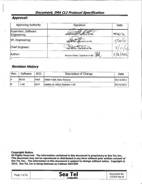
Document, IMA CLI Protocol Specification - Livewire Connections Ltd
Document, IMA CLI Protocol Specification - Livewire Connections Ltd
Document, IMA CLI Protocol Specification - Livewire Connections Ltd
Create successful ePaper yourself
Turn your PDF publications into a flip-book with our unique Google optimized e-Paper software.
Command Line Tree Structure:<strong>Document</strong>, <strong>IMA</strong> <strong>CLI</strong> <strong>Protocol</strong> <strong>Specification</strong>interface see page 3antenna see page 10satellite see page 11setship see page 12system see page 13satellite_fav see page 19error see page 19allinterface see page 20antenna see page 24satellite see page 25showship see page 26system see page 26satellite_fav see page 31error see page 31status see page 32savedealer_config>restorehelpreboottestdealer_configfactorylistprogresscancelstartoostistserialrebootupgradesystemusbrebootallnetworkrebootnameversionnumberquit | exitdatetimemxpicupinggatewaydnsLegend:NormalEnd of commandInformationEnd of command with “default”Not supported Page 2 of 52<strong>Document</strong> No135163 Rev B
Set Interface (1 of 7)<strong>Document</strong>, <strong>IMA</strong> <strong>CLI</strong> <strong>Protocol</strong> <strong>Specification</strong>ip v4 netmask v4 gateway v4 dns v4 macnetworktcp:0 see page 6tcp:1 see page 6tcp:2 see page 7tcp:3 see page 7udp see page 8setinterfaceweb see page 8secure_web see page 8rf_m&c [4800 .. 115200]passthrough [4800 .. 115200]aux232 [4800 .. 115200]baudratemxpobm_modem [4800 .. 115200]nmea_0183 [4800 .. 115200]console [4800 .. 115200]icu console [4800 .. 115200]Page 3 of 52<strong>Document</strong> No135163 Rev B
Set Interface (2 of 7)<strong>Document</strong>, <strong>IMA</strong> <strong>CLI</strong> <strong>Protocol</strong> <strong>Specification</strong>offggagllhdd1hdghdmhdtrmcvtgoffggagllhdd2hdghdmhdtrmcmessagevtgoffggagllhdd3hdghdmhdtrmcvtgset interface nmea_0183offggagllhdd4hdghdmhdtrmcvtg1 1 - 10interval2 1 - 103 1 - 104 1 - 10Page 4 of 52<strong>Document</strong> No135163 Rev B
<strong>Document</strong>, <strong>IMA</strong> <strong>CLI</strong> <strong>Protocol</strong> <strong>Specification</strong>Set Interface (3 of 7)onflow_ctrloffconsoleclimodelegacyusb_portmodelegacyclisetinterfaceheadinghddheading_idhdghdmgyrohdtno_gyrofixed360:1type90:136:11:1sbsnmeaPage 5 of 52<strong>Document</strong> No135163 Rev B
Set Interface (4 of 7)<strong>Document</strong>, <strong>IMA</strong> <strong>CLI</strong> <strong>Protocol</strong> <strong>Specification</strong>set interface network tcp:0portenablesecuremodeonoffonofflegacycliopenamipset interface network tcp:1portenablesecuremodeonoffonofflegacycliopenamipPage 6 of 52<strong>Document</strong> No135163 Rev B
Set Interface (5 of 7)<strong>Document</strong>, <strong>IMA</strong> <strong>CLI</strong> <strong>Protocol</strong> <strong>Specification</strong>set interface network tcp:2portenablesecuremodeonoffonofflegacycliopenamipset interface network tcp:3portenablesecuremodeonoffonofflegacycliopenamipPage 7 of 52<strong>Document</strong> No135163 Rev B
Set Interface (6 of 7)<strong>Document</strong>, <strong>IMA</strong> <strong>CLI</strong> <strong>Protocol</strong> <strong>Specification</strong>set interface network udpportenableonoffset interface network webportenableonoffset interface network secure_webportenableonoffPage 8 of 52<strong>Document</strong> No135163 Rev B
Set Interface (7 of 7)<strong>Document</strong>, <strong>IMA</strong> <strong>CLI</strong> <strong>Protocol</strong> <strong>Specification</strong>openamiptms_1modem_iotms_2modem_rj45low_lockxmod_lock_in_polset interface primary_reflectorhi_lockonxmod_lockofflow_blockblockage_outhi_blockopenamiptms_1modem_iotms_2modem_rj45low_lockxmod_lock_in_polset interface secondary_reflectorhi_lockonxmod_lockofflow_blockblockage_outhi_blockPage 9 of 52<strong>Document</strong> No135163 Rev B
<strong>Document</strong>, <strong>IMA</strong> <strong>CLI</strong> <strong>Protocol</strong> <strong>Specification</strong>namemodelaz_target [0.0 .. 359.9]el_target [0.0 .. 90.0]cl_target [-30.0 .. 30.0]setantennalinear_pol_target [-92.0 .. 182.0]circular_pol_target [-92.0 .. 182.0]trackingonoffsearchingonoffPage 10 of 52<strong>Document</strong> No135163 Rev B
<strong>Document</strong>, <strong>IMA</strong> <strong>CLI</strong> <strong>Protocol</strong> <strong>Specification</strong>descriptionlon[0.0 - 360.0] [E/W]freqskew12band34lhcprhcptx_polsetsatellitehvspiralsearch_patterninclinesky_searchprimary_reflectorreflectorsecondary_reflectorxpollnbcopoloffauto_modeonthresholdauto_offset 0 - 300value 0 - 3000Page 11 of 52<strong>Document</strong> No135163 Rev B
<strong>Document</strong>, <strong>IMA</strong> <strong>CLI</strong> <strong>Protocol</strong> <strong>Specification</strong>namesetshiplatlon[0.0 - 90.0] [N/S][0.0 - 360.0] [E/W]headingPage 12 of 52<strong>Document</strong> No135163 Rev B
Set System (1 of 6)<strong>Document</strong>, <strong>IMA</strong> <strong>CLI</strong> <strong>Protocol</strong> <strong>Specification</strong>auto_trimauto_threshel [0.0 .. 90.0]trimaz [0.0 .. 359.9]sensitivityelazlinear_offset [-45.0 - 45.0]set system primary_reflectorpolangdriveautomanualcircular_offset [-45.0 - 45.0]modeautomanualincrementsearchlimitdelayscan_rateincline_limitPage 13 of 52<strong>Document</strong> No135163 Rev B
Set System (2 of 6)<strong>Document</strong>, <strong>IMA</strong> <strong>CLI</strong> <strong>Protocol</strong> <strong>Specification</strong>modeonoffaz_drive [0 - 100]dishscanel_drive [0 - 100]set system primary_reflectorcl_drive [0 - 100]phase [-90.0 - 90.0]lnb lo band [1-4] Page 14 of 52<strong>Document</strong> No135163 Rev B
Set System (3 of 6)<strong>Document</strong>, <strong>IMA</strong> <strong>CLI</strong> <strong>Protocol</strong> <strong>Specification</strong>auto_trimauto_threshtrimel [0.0 .. 90.0]az [0.0 .. 359.9]sensitivityelazlinear_offset [-45.0 - 45.0]set system secondary_reflectorpolangdriveautomanualcircular_offset [-45.0 - 45.0]modeautomanualincrementsearchlimitdelayscan_rateincline_limitSet System (4 of 6)Page 15 of 52<strong>Document</strong> No135163 Rev B
<strong>Document</strong>, <strong>IMA</strong> <strong>CLI</strong> <strong>Protocol</strong> <strong>Specification</strong>modeonoffaz_drive [0 - 100]dishscanel_drive [0 - 100]set system secondary_reflectorcl_drive [0 - 100]phase [-90.0 - 90.0]lnb lo band [1-4] Page 16 of 52<strong>Document</strong> No135163 Rev B
Set System (5 of 6)<strong>Document</strong>, <strong>IMA</strong> <strong>CLI</strong> <strong>Protocol</strong> <strong>Specification</strong>retargethomeflag_trimonsatrefoffprofile0.2step_res0.1setsystem0.05descriptionblockage_zone zone [1..4]az_start [0.0 .. 360.0]az_end [0.0 .. 360.0]el [0.0 .. 90.0]azref_limitclbalance_modeeltech_contactPage 17 of 52<strong>Document</strong> No135163 Rev B
Set System (6 of 6)<strong>Document</strong>, <strong>IMA</strong> <strong>CLI</strong> <strong>Protocol</strong> <strong>Specification</strong>el [0 .. 500]motor_gaincl [0 .. 500]az [0 .. 500]elposnegposdrive_orientationclnegposaznegvlim_ratio [1 .. 8]setsystemslow_scan_modeoffonslow_scan_vlimonauto_sat_load_search_failoffonauto_sat_load_resetoff1num_reflector2nbifdvbreceiverscpc70MHzPage 18 of 52<strong>Document</strong> No135163 Rev B
<strong>Document</strong>, <strong>IMA</strong> <strong>CLI</strong> <strong>Protocol</strong> <strong>Specification</strong>set satellite_fav newsetsatellite_fav:xactiveclearseterrormessageserroronoffall[error number]Page 19 of 52<strong>Document</strong> No135163 Rev B
Show Interface (1 of 5)<strong>Document</strong>, <strong>IMA</strong> <strong>CLI</strong> <strong>Protocol</strong> <strong>Specification</strong>ipv4netmaskv4gatewayv4dnsv4tcp:0 see page 20networktcp:1 see page 20tcp:2 see page 20tcp:3 see page 21udp see page 21web see page 21showinterfacesecure_web see page 21macbaudraterf_m&cpassthroughmxpaux232obm_modemnmea_0183consoleicuconsolePage 20 of 52<strong>Document</strong> No135163 Rev B
Show Interface (2 of 5)<strong>Document</strong>, <strong>IMA</strong> <strong>CLI</strong> <strong>Protocol</strong> <strong>Specification</strong>1message23show interface nmea_018341interval234consoleflow_ctrlmodeshowinterfaceusb_portmodeheadinggyroheading_idtypePage 21 of 52<strong>Document</strong> No135163 Rev B
Show Interface (3 of 5)<strong>Document</strong>, <strong>IMA</strong> <strong>CLI</strong> <strong>Protocol</strong> <strong>Specification</strong>portshow interface network tcp:0enablesecuremodeportshow interface network tcp:1enablesecuremodeportshow interface network tcp:2enablesecuremodePage 22 of 52<strong>Document</strong> No135163 Rev B
Show Interface (4 of 5)<strong>Document</strong>, <strong>IMA</strong> <strong>CLI</strong> <strong>Protocol</strong> <strong>Specification</strong>portshow interface network tcp:3enablesecuremodeshow interface network udpportenableshow interface network webportenableshow interface network secure_webportenablePage 23 of 52<strong>Document</strong> No135163 Rev B
Show Interface (5 of 5)<strong>Document</strong>, <strong>IMA</strong> <strong>CLI</strong> <strong>Protocol</strong> <strong>Specification</strong>modem_ioshow interface primary_reflectorxmod_lock_in_polxmod_lockblockage_outmodem_ioshow interface secondary_reflectorxmod_lock_in_polxmod_lockblockage_outPage 24 of 52<strong>Document</strong> No135163 Rev B
<strong>Document</strong>, <strong>IMA</strong> <strong>CLI</strong> <strong>Protocol</strong> <strong>Specification</strong>namemodelaz_targetel_targetshowantennacl_targetlinear_pol_targetcircular_pol_targettrackingsearchingPage 25 of 52<strong>Document</strong> No135163 Rev B
<strong>Document</strong>, <strong>IMA</strong> <strong>CLI</strong> <strong>Protocol</strong> <strong>Specification</strong>descriptionlonfreqskewbandshowsatellitetx_polsearch_patternreflectorlnbauto_modethresholdauto_offsetvalueshowshipnamelatlonheadingPage 26 of 52<strong>Document</strong> No135163 Rev B
Show System (1 of 4)<strong>Document</strong>, <strong>IMA</strong> <strong>CLI</strong> <strong>Protocol</strong> <strong>Specification</strong>trimelazsensitivityelazlinear_offsetpolangdrivecircular_offsetmodeincrementshow system primary_reflectorsearchlimitdelayscan_rateincline_limitmodeaz_drivedishscancl_driveel_drivephaselnb lo band [1-4]Page 27 of 52<strong>Document</strong> No135163 Rev B
Show System (2 of 4)<strong>Document</strong>, <strong>IMA</strong> <strong>CLI</strong> <strong>Protocol</strong> <strong>Specification</strong>trimelazsensitivityelazlinear_offsetpolangdrivecircular_offsetmodeincrementshow system secondary_reflectorsearchlimitdelayscan_rateincline_limitmodeaz_drivedishscancl_driveel_drivephaselnb lo band [1-4]Page 28 of 52<strong>Document</strong> No135163 Rev B
Show System (3 of 4)<strong>Document</strong>, <strong>IMA</strong> <strong>CLI</strong> <strong>Protocol</strong> <strong>Specification</strong>profileserial_nodescriptionhomeflag_trimaz_startblockage_zone zone [1..4]showsystemstep_resaz_endelsatrefazref_limitclbalance_modeeltech_contactPage 29 of 52<strong>Document</strong> No135163 Rev B
Show System (4 of 4)<strong>Document</strong>, <strong>IMA</strong> <strong>CLI</strong> <strong>Protocol</strong> <strong>Specification</strong>elmotor_gainclazeldrive_orientationclvlim_ratioazshowsystemslow_scan_modeslow_scan_vlimauto_sat_load_search_failauto_sat_load_resetnum_reflectorreceiverPage 30 of 52<strong>Document</strong> No135163 Rev B
<strong>Document</strong>, <strong>IMA</strong> <strong>CLI</strong> <strong>Protocol</strong> <strong>Specification</strong>show parameter profileshow satellite_fav allshowsatellite_fav:xshow error allPage 31 of 52<strong>Document</strong> No135163 Rev B
<strong>Document</strong>, <strong>IMA</strong> <strong>CLI</strong> <strong>Protocol</strong> <strong>Specification</strong>alllatshiplonheadinglonfreqskewbandtx_polsatellitesearch_patternreflectorlnbagcshowstatusthresholdazelclpolrelantennaagcinitializingtrackingtargetingsearchingmodem_locksystemtx_mutesearch_delay_cntPage 32 of 52<strong>Document</strong> No135163 Rev B
1.0 Command Description:<strong>Document</strong>, <strong>IMA</strong> <strong>CLI</strong> <strong>Protocol</strong> <strong>Specification</strong>setshowquitexitsavehelpdefault allrebootupgradeversiontestChange active settings or parameters.Display/query active settings or parameters.Close <strong>CLI</strong> Ethernet connection.Close <strong>CLI</strong> Ethernet connection.Save parameters or settings to the flash (INI file).Display a description for proper command usage.Reset the system to default settings.Reboot the system.Upgrade firmware.Display unit name, software date and time of build, and version.Run automated tests programmed as part of the system.2.0 Detailed Command Description:3. set/showSet command changes the active settings or parameters. Show command displays the active settings orparameters.3.1 interfaceStores all interface related settings of the system.3.1.1 networkStores all Ethernet related settings, such as IP address, gateway, and port information.3.1.1.1 macStores the MAC address of the system. Show only.3.1.1.2 ip_addrStores the IP address of the system.3.1.1.2.1 v4 This set/show the IPv4 address of the system. New IP will take effect after save andreboot.Range: (0-223).(0-255).(0-255).(0-255).Default: 10.1.1.1003.1.1.3 netmaskStores the network mask of the system.3.1.1.3.1 v4 This set/show the IPv4 network mask of the system. New netmask IP will take effectafter save and reboot.Range: (0-223).(0-255).(0-255).(0-255).Default: 255.255.255.03.1.1.4 gatewayStores the gateway address of the system.3.1.1.4.1 v4 This set/show the IPv4 gateway of the system. New gateway IP will take effect aftersave and reboot.Range: (0-223).(0-255).(0-255).(0-255).Default: 10.1.1.13.1.1.5 dnsStores the DNS (Domain Name System) server address in the network.3.1.1.5.1 v4 This set/show the IPv4 DNS server in the network.Range: (0-223).(0-255).(0-255).(0-255).Default: 10.1.1.2053.1.1.6 udpStores the UDP port information.Page 33 of 52<strong>Document</strong> No135163 Rev B
<strong>Document</strong>, <strong>IMA</strong> <strong>CLI</strong> <strong>Protocol</strong> <strong>Specification</strong>3.1.1.6.1 port This set/show the UDP port number.Range: 0-65535.Default: 30003.1.1.6.2 enable Enable or disable the port.Value: on, off.Default: on.3.1.1.7 webStores the Web port information.3.1.1.7.1 port This set/show the Web port number.Range: 0-65535.Default: 803.1.1.7.2 enable Enable or disable the port.Value: on, off.Default: on.3.1.1.8 secure_webStores the Secure Web port information.3.1.1.8.1 port This set/show the Web port number.Range: 0-65535.Default: 4433.1.1.8.2 enable Enable or disable the port.Value: on, off.Default: on.3.1.1.9 tcp:0, tcp:1, tcp:2, tcp:3These groups store the TCP port information.3.1.1.9.1 port This set/show the port number.Range: 0-65535.Default:tcp:0 = 2000tcp:1 = 2001tcp:2 = 2002tcp:3 = 20033.1.1.9.2 enable Enable or disable the port.Value: on, off.Default: on.3.1.1.9.3 mode This set/show the mode of the port.Value: legacy, openamip, cli.Default:tcp:0 = legacytcp:1 = legacytcp:2 = openamiptcp:3 = cli3.1.1.9.4 secure This set/show the secure mode of this interface. ON means access to this interface willrequire proper credential (login). OFF means no credential required.Value: on, off.Page 34 of 52<strong>Document</strong> No135163 Rev B
<strong>Document</strong>, <strong>IMA</strong> <strong>CLI</strong> <strong>Protocol</strong> <strong>Specification</strong>Default:tcp:0 = offtcp:1 = offtcp:2 = offtcp:3 = on3.1.2 baudrateStores the baud rate for all serial ports.3.1.2.1 rf_m&c This set/show the baud rate of rf_m&c serial port.Range: 4800 – 115200 (bps).Default: 9600 bps.3.1.2.2 passthrough This set/show the baud rate of passthrough serial port.Range: 4800 – 115200 (bps).Default: 9600 bps.3.1.2.3 mxpThis set/show the baud rate of MXP’s serial port.3.1.2.3.1 aux232 This set/show the baud rate of Aux232 serial port.Range: 4800 – 115200 (bps).Default: 9600 bps.3.1.2.3.2 obm_modem This set/show the baud rate of OBM_Modem serial port.Range: 4800 – 115200 (bps).Default: 4800 bps.3.1.2.3.3 nmea_0183 This set/show the baud rate of NMEA 0183 port.Range: 4800 – 115200 (bps).Default: 4800 bps.3.1.2.3.4 console This set/show the baud rate of console port.Range: 4800 – 115200 (bps).Default: 115200 bps.3.1.2.4 icuThis set/show the baud rate of ICU’s serial port.3.1.2.4.1 console This set/show the baud rate of console serial port.Range: 4800 – 115200 (bps).Default: 115200 bps.3.1.3 nmea_0183Stores NMEA 0183 settings.3.1.3.1 messageStores the GPS message the system sends/streams. Support up to four different settings(defined by the index).3.1.3.1.1 1, 2, 3, 4 This set/show the GPS message the system sends/streams for particular index.Value: OFF, GGA, GLL, HDD, HDG, HDM, HDT, RMC, VTG.Default:1 = GLL2 = GGA3 = OFF4 = OFFPage 35 of 52<strong>Document</strong> No135163 Rev B
<strong>Document</strong>, <strong>IMA</strong> <strong>CLI</strong> <strong>Protocol</strong> <strong>Specification</strong>3.1.3.2 intervalStores the interval of the GPS message the system sends/streams. Support up to four differentsettings (defined by the index).3.1.3.2.1 1, 2, 3, 4 This set/show the interval of the GPS message the system sends/streams for particularindex.Range: 1 - 10.Default:1 = 52 = 53 = 14 = 13.1.4 consoleStores console settings.3.1.4.1 flow_ctrl This set/show the console’s hardware flow control (RTS/CTS).Value: on, off.Default: off.3.1.4.2 mode This set/show the console’s mode.Value: cli, legacy.Default: cli.3.1.5 usb_portStores USB port settings.3.1.5.1 mode This set/show the USB port’s mode. In <strong>CLI</strong> mode it requires credential (login).Value: legacy, cli.Default: cli.3.1.6 gyroStores gyro setting.3.1.6.1 heading_id This set/show the NMEA 0183 heading ID the system listens to.Value: HDD, HDG, HDM, HDT.Default: HDT.3.1.6.2 heading This set/show the fixed heading.Value: 0.0 – 360.0Default: 0.03.1.6.3 type This set/show gyro mode.Value: no_gyro, fixed, 360:1, 90:1, 36:1, 1:1, sbs, nmea.Default: fixed.3.1.7 primary_reflector, secondary_reflectorStores reflector-specific settings.3.1.7.1 modem_io This set/show external modem IO type.Value: modem_rj485, tms_1, tms_2, openamip.Default: modem_rj485.3.1.7.2 xmod_lock_in_pol This set/show external modem lock input polarity for selected modem IO. Determines thepolarity (high or low) used by the external modem to indicate lock state.Value: low_lock, hi_lock.Default: low_lock.Page 36 of 52<strong>Document</strong> No135163 Rev B
<strong>Document</strong>, <strong>IMA</strong> <strong>CLI</strong> <strong>Protocol</strong> <strong>Specification</strong>3.1.7.3 blockage_output This set/show external modem lock input polarity for selected modem IO. Determines thepolarity (high or low) used by the external modem to indicate block state.Value: low_block, hi_block.Default: low_block.3.1.7.4 xmod_lock This set/show external modem lock state. Determines whether the system listen to the locksignal from external modem or not. For Tx/Rx system this option should be on because it is themodem that identifies the satellite. For Rx only system this option should be off since it eitheruses NID to identify the satellite (via DVB) or the signal-above-threshold.Value: on, off.Default: on.3.2 antennaStores all antenna related settings of the system.3.2.1 name This set/show antenna name. Support up to 32 characters.Default: [Enter Description]3.2.2 model This set/show antenna model. Support up to 32 characters.Default: [Enter Model]3.2.3 az_target This set/show Azimuth target, a position on azimuth axis that the antenna will target.Range: 0.0 – 359.9 (degree)Default: 0.03.2.4 el_target This set/show Elevation target, a position on elevation axis that the antenna will target. 0 is theposition when the reflector is facing horizon, parallel to the ground. 90 is the position when thereflector is perpendicular to the ground (high look).Range: 0.0 – 90.0 (degree)Default: 0.03.2.5 cl_target This set/show Cross-Level target, a position on cross-level axis that the antenna will target.Range: -30.0 – 30.0 (degree)Default: 0.03.2.6 linear_pol_target This set/show linear polarity angle target.Range: -92.0 – 182.0 (degree)Default: 0.03.2.7 circular_pol_target This set/show circular polarity angle target.Range: -92.0 – 182.0 (degree)Default: 0.03.2.8 tracking This set/show tracking mode state.Value: on, off.Default: on.3.2.9 searching This set/show searching mode state.Value: on, off.Default: off.Page 37 of 52<strong>Document</strong> No135163 Rev B
<strong>Document</strong>, <strong>IMA</strong> <strong>CLI</strong> <strong>Protocol</strong> <strong>Specification</strong>3.3 satelliteStores all antenna related settings of the system.3.3.1 description This set/show satellite description. Support up to 32 characters.Default: [Enter Description]3.3.2 lon This set/show satellite longitude.Range: [0.0 - 360.0] [E/W]Default: 101.0 W3.3.3 freq This set/show satellite frequency.Range: 950.0 – 2150.0 (MHz)Default: 1234.5673.3.4 skew This set/show satellite skew.Range: -90.0 – 90.0 (degree)Default: 0.03.3.5 band This set/show satellite band.Range: 1 - 4Default: 23.3.6 tx_pol This set/show satellite transmit polarity. The possible values cover linear and circular polarization.Value: H, V, L, R.Default: H.3.3.7 search_pattern This set/show search pattern that is used to search this satellite.Value: spiral, inclined, sky_search.Default: spiral.3.3.8 reflector This set/show the antenna or reflector that is used for this satellite.Value: primary_reflector, secondary_reflector.Default: primary_reflector.3.3.9 lnb This set/show the LNB that is used for this satellite.Value: copol, xpol.Default: xpol.3.3.10 thresholdStores the threshold settings. The threshold value serves as the main signal threshold to be usedfor search and dishscan operation.3.3.10.1 auto_mode This set/show the threshold mode used for this satellite.Value: on, offDefault: on.3.3.10.2 auto_offset This set/show the offset for auto threshold mode. Applicable only when threshold mode is auto.Value: 0 - 300Default: 100.3.3.10.3 manual_value This set/show the manual threshold value. Applicable only when threshold mode is auto.Value: 0 - 3000Default: 100.Page 38 of 52<strong>Document</strong> No135163 Rev B
<strong>Document</strong>, <strong>IMA</strong> <strong>CLI</strong> <strong>Protocol</strong> <strong>Specification</strong>3.4 shipStores ship related settings.3.4.1 name This set/show the ship name. Support up to 32 characters.Default: [Enter Ship Name]3.4.2 heading This set/show the ship heading.Range: 0.0 – 360.0Default: 0.03.4.3 lat This set/show the ship latitude.Range: [0.0 - 90.0] [N/S]Default: 0.0 N3.4.4 lon This set/show the ship longitude.Range: [0.0 - 360.0] [E/W]Default: 0.0 E3.5 systemStores system related settings, both reflector-specific and common settings.3.5.1 primary_reflector, secondary_reflectorStores reflector-specific settings.3.5.1.1 auto_threshThis set will start/initiate calculate Auto Theshold operation. This is an action command.3.5.1.2 auto_trimThis set will start/initiate calculate Auto Trim operation. This is an action command.3.5.1.3 trimStores trim setting property. Trim is used to apply offset to align the antenna.3.5.1.3.1 el This set/show trim for elevation axis.Value: -45.0 – 45.0 (degree)Default: 0.03.5.1.3.2 az This set/show trim for azimuth axis.Value: -180.0 – 180.0 (degree)Default: 0.03.5.1.4 sensitivityStores sensitivity settings for elevation and azimuth axes. Sensitivity affects the signal thresholdused in dishscan operation. Higher the sensitivity lower the threshold will be.3.5.1.4.1 el This set/show sensitivity for elevation axis.Range: 10 – 100 (%)Default: 503.5.1.4.2 az This set/show sensitivity for elevation axis.Range: 10 – 100 (%)Default: 503.5.1.5 polangStores polarity angle of the antenna feed.3.5.1.5.1 drive This set/show polang drive type.Value: auto, manual.Default: autoPage 39 of 52<strong>Document</strong> No135163 Rev B
<strong>Document</strong>, <strong>IMA</strong> <strong>CLI</strong> <strong>Protocol</strong> <strong>Specification</strong>3.5.1.5.2 linear_offset This set/show linear polarity angle offset. Applicable only if the type is linear.Range: -45.0 – 45.0 (degree)Default: 0.03.5.1.5.3 circular_offset This set/show circular polarity angle offset. Applicable only if the type is circular.Range: -45.0 – 45.0 (degree)Default: 0.03.5.1.6 searchStores search operation settings. Search operation is performed when the antenna is unable tolocate a satellite.3.5.1.6.1 auto This set/show auto search mode. When auto search mode is on (recommended) theantenna will do the search automatically.Value: on, off.Default: on3.5.1.6.2 increment This set/show search increment value. The increment value determines how big theantenna needs to increment relative to the previous search path/line. Smaller the incrementfiner the antenna will scan the search area, and it will take longer to reach the search limit.Range: 0.1 – 10.0 (degree)Default: 1.03.5.1.6.3 limit This set/show search limit. The limit defines how big the search area. It is measured fromthe start search position.Range: 1.0 – 20.0 (degree)Default: 20.03.5.1.6.4 delay This set/show search delay. This delay determines how long the antenna will wait beforeinitiating the next search when the current search failed. It also determines how long theantenna waits before initiating search operation when the signal dropped below thethreshold (lost satellite indication).Range: 0 – 200 (second)Default: 303.5.1.6.5 scan_rate This set/show search scan rate. Determines how fast the antenna move during searchoperation. It is in angular velocity measurement unit.Range: 0.1 – 10.0 (degree/second)Default: 2.03.5.1.6.6 incline_limit This set/show incline search limit. Applicable when the search pattern is inclined search.The limit defines how big the search area is. It is measured from the start search position.Range: 2.0 – 40.0 (degree)Default: 16.03.5.1.7 dishscanStores dishscan operation settings. Dishscan enabled the antenna to keep pointing to aposition that give the strongest signal read. During dishscan operation the antenna makessmall, circular movement.3.5.1.7.1 mode This set/show dishscan mode. Enable or disable dishscan.Value: on, off.Default: on.Page 40 of 52<strong>Document</strong> No135163 Rev B
<strong>Document</strong>, <strong>IMA</strong> <strong>CLI</strong> <strong>Protocol</strong> <strong>Specification</strong>3.5.1.7.2 az_drive This set/show azimuth axis dishscan multiplier value. 0 means no dishscan for azimuthaxis. Higher the number bigger the dishscan motion.Range: 0 – 100Default: 103.5.1.7.3 cl_drive This set/show cross-level axis dishscan multiplier value. 0 means no dishscan for crosslevelaxis. Higher the number bigger the dishscan motion.Range: 0 – 100Default: 103.5.1.7.4 el_drive This set/show elevation axis dishscan multiplier value. 0 means no dishscan for elevationaxis. Higher the number bigger the dishscan motion.Range: 0 – 100Default: 103.5.1.7.5 phase This set/show dishscan phase. Dishscan phase is used to control motor output due tomovement lagging due to inertia. Large pedestal needs bigger number.Value: -45, 0, 45, 90Default: 03.5.1.8 lnbStores LNB related setting.3.5.1.8.1 loStores Local Oscillator related setting.3.5.1.8.1.1 band:1, band:2, band:3, band:4 This set/show local oscillator frequency of the LNB. The local oscillator frequencyshould match the carrier used by the satellite.Range: 1.0 – 200.0 (GHz)Default:band:1 = 10.000band:2 = 10.700band:3 = 11.300band:4 = 9.7503.5.2 retargetThis set will start/initiate retarget operation. This is an action command.3.5.3 homeflag_trim This set/show home-flag trim value. Determines the adjustment offset for home-flag sensor.Range: -180.0 – 180.0 (degree)Default: 0.03.5.4 satref This set/show satellite reference mode. When Satellite Reference mode is on, the antenna willignore ship heading and it uses satellite signal to track.Value: on, off.Default: off.3.5.5 blockage_zoneStores all blockage-zone configurations.3.5.5.1 1, 2, 3, 4Stores blockage-zone configurations based on index.3.5.5.1.1 description This set/show blockage-zone description. Support up to 32 characters.Default: [Enter Description]3.5.5.1.2 rel_start This set/show blockage-zone relative start. The relative start for this zone.Range: 0.0 – 360.0 (degree)Default: 0.0Page 41 of 52<strong>Document</strong> No135163 Rev B
<strong>Document</strong>, <strong>IMA</strong> <strong>CLI</strong> <strong>Protocol</strong> <strong>Specification</strong>3.5.5.1.3 rel_end This set/show blockage-zone relative end. The relative end for this zone.Range: 0.0 – 360.0 (degree)Default: 0.03.5.5.1.4 el This set/show blockage-zone elevation. Determines the end of elevation for this zone. Thestart of elevation is always at elevation = 0.Range: 0.0 – 90.0 (degree)Default: 90.03.5.6 profile This set/show hardware profile ID of the system. Please find the hardware profile ID on the stickerattached to the antenna.Default: 0.3.5.7 serial_numberStores serial number. Show only.3.5.8 auto_sat_load_search_fail This set/show auto satellite load after search failed. When the mode is on, the antenna will loadand go to the last known good satellite when the search operation failed.Value: on, off.Default: on.3.5.9 auto_sat_load_reset This set/show auto satellite load after hot reset or power up. When the mode is on, the antenna willload and go to the last known good satellite upon hot reset or power up.Value: on, off.Default: on.3.5.10 step_res This set/show step resolution. Step resolution determines the step size for 1 move during searchoperation.Value: 0.2, 0.1, 0.05 (degree)Default: 0.13.5.11 balance_mode This set/show balance mode. When in balance mode the antenna will not moving and allow thetechnician to balance the antenna.Value: on, off.Default: off3.5.12 ref_limitStores reference limit mode for all axes. When Reference Limit mode is on, the system will clip theerror to 3. This is mainly used in the land, where the abrupt erratic movement of the vehicleintroduces abrupt error.3.5.12.1 az This set/show reference limit mode for azimuth axis.Value: on, off.Default: off.3.5.12.2 cl This set/show reference limit mode for cross-level axis.Value: on, off.Default: off.3.5.12.3 el This set/show reference limit mode for elevation axis.Value: on, off.Default: off.3.5.13 motor_gainStores motor gain for all axes. The gain determines the motor torque. Antenna system with largepedestal required higher gain than the one with smaller pedestal.Page 42 of 52<strong>Document</strong> No135163 Rev B
<strong>Document</strong>, <strong>IMA</strong> <strong>CLI</strong> <strong>Protocol</strong> <strong>Specification</strong>3.5.13.1 az This set/show azimuth motor gain.Range: 0 - 500.Default: 15 (model specific database will override).3.5.13.2 cl This set/show cross-level motor gain.Range: 0 - 500.Default: 15 (model specific database will override).3.5.13.3 el This set/show azimuth motor gain.Range: 0 - 500.Default: 15 (model specific database will override).3.5.14 drive_orientationStores motor drive orientation all axes. This setting will determine how the motor installed ormounted on the pedestal (model-specific). E.g. Clockwise move is forward move for Azimuth axis.If the azimuth motor is installed in reverse position, a positive output to the motor will result in thepedestal move counter clockwise on azimuth axis. In this case the drive orientation for azimuthmotor will be reverse.3.5.14.1 az This set/show azimuth motor drive orientation.Value: fwd, rev.Default: fwd (model specific database will override).3.5.14.2 cl This set/show cross-level motor drive orientation.Value: fwd, rev.Default: fwd (model specific database will override).3.5.14.3 el This set/show elevation motor drive orientation.Value: fwd, rev.Default: fwd (model specific database will override).3.5.15 vlim_ratio This set/show velocity limit ratio. Velocity limit ratio is the scale factor that is applied to prevent theovershooting from happening by limiting the velocity of the antenna. Closer the antenna to thetarget, lower the limit will be. Bigger the pedestal, bigger the ratio will be.Value: 1 - 8.Default: 1 (model specific database will override).3.5.16 slow_scan_mode This set/show slow scan mode. When the mode is on, the antenna will be in slow scan mode. Thisis used for testing and diagnostic only.Value: on, off.Default: off.3.5.17 slow_scan_vlim This set/show slow scan velocity limit. Similar to velocity limit, but this one applies when theantenna is in slow scan mode.Range: 0.1 – 9.9.Default: 2.0.3.5.18 num_reflector This set/show the number of reflectors the antenna has. When the number of reflector is one, onlythe primary sections under system will be available.Range: 1 – 2.Default: 1.3.5.19 receiver This set/show the receiver type.Range: NBIF, SCPC, DVB, 70MHZ.Default: SCPC.Page 43 of 52<strong>Document</strong> No135163 Rev B
<strong>Document</strong>, <strong>IMA</strong> <strong>CLI</strong> <strong>Protocol</strong> <strong>Specification</strong>3.5.20 tech_contactThis show technical contact information. Show only.Value: Sea Tel Inc., a Cobham company4030 Nelson Ave.Concord, CA 94520USAE: seatelservice@cobham.comT: +1 (925) 798-23993.6 satellite_fav3.6.1 newAdd a new favorite satellite. This is interactive mode command. First it will display the index of thisnew favorite satellite, and then it will prompt to enter each satellite parameters one by one.3.6.2 0 - 499Favorite satellite with index. It’s written with colon as separator. Example: satellite_fav:13.6.2.1 clearThis deletes the favorite satellite.3.6.2.2 activeThis sets the favorite satellite to be the active satellite. The antenna will target this satellite.3.7 status3.7.1 shipShow ship related settings.3.7.1.1 headingThis show the ship heading.Range: 0.0 – 360.0Default: 0.03.7.1.2 latThis show the ship latitude.Range: 90.0 N – 90.0 SDefault: 0.0 N3.7.1.3 lonThis show the ship longitude.Range: [0.0 - 360.0] [E/W]Default: 0.0 E3.7.2 satelliteStores all antenna related settings of the system.3.7.2.1 lonThis show satellite longitude.Range: 180.0 W – 180.0 EDefault: 0.0 E3.7.2.2 freqThis show satellite frequency.Range: 950.0 – 2150.0 (MHz)Default: 1234.5673.7.2.3 skewThis show satellite skew.Range: -90.0 – 90.0 (degree)Default: 0.03.7.2.4 bandThis show satellite band.Range: 1 - 4Default: 1Page 44 of 52<strong>Document</strong> No135163 Rev B
<strong>Document</strong>, <strong>IMA</strong> <strong>CLI</strong> <strong>Protocol</strong> <strong>Specification</strong>3.7.2.5 tx_polThis show satellite transmit polarity.Value: H, V, L, R.Default: H.3.7.2.6 search_patternThis show search pattern that is used to search this satellite.Value: spiral, inclined, sky_search.Default: spiral.3.7.2.7 reflectorThis show the reflector that is used for this satellite.Value: primary_reflector, secondary_reflector.Default: primary_reflector.3.7.2.8 lnbThis show the LNB that is used for this satellite.Value: copol, xpol.Default: xpol.3.7.2.9 agcThis show the AGC value.3.7.2.10 thresholdThis show the actual threshold value being used by the antenna.3.7.3 antennaStores all antenna related settings of the system.3.7.3.1 azThis show current Azimuth position.Range: 0.0 – 360.0 (degree)Default: 0.03.7.3.2 elThis show current Elevation position.Range: 0.0 – 90.0 (degree)Default: 0.03.7.3.3 clThis show current Cross-Level position.Range: -30.0 – 30.0 (degree)Default: 0.03.7.3.4 relativeThis show current Relative position.Range: 0.0 – 360.0 (degree)Default: 0.03.7.3.5 linear_polThis show current linear polarity angle.Range: -92.0 – 182.0 (degree)Default: 0.03.7.3.6 circular_polThis show current circular polarity angle.Range: -92.0 – 182.0 (degree)Default: 0.03.7.3.7 agcThis show AGC value.3.7.3.8 initializingThis show initializing mode state.Value: on, off.3.7.3.9 trackingThis show tracking mode state.Value: on, off.Page 45 of 52<strong>Document</strong> No135163 Rev B
<strong>Document</strong>, <strong>IMA</strong> <strong>CLI</strong> <strong>Protocol</strong> <strong>Specification</strong>3.7.3.10 targetingThis show targeting mode state.Value: on, off.3.7.3.11 searchingThis show searching mode state.Value: on, off.3.7.4 systemStores system related settings.3.7.4.1 modem_lockThis show modem lock status the system got from modem.Value: on, off.3.7.4.2 tx_muteThis show the cause of transmit mute. Transmit mute can happen because the antenna is inthe blockage zone, manually muted, or due to stability.Value: manual, stability, block, and threshold.3.7.4.3 search_delay_countThis show the search delay count left. It is a countdown.3.8 errorClears/acknowledges or shows error(s).3.8.1 messagesThis set enables/disables the critical error messages on Console port. For “off”, it disablestemporarily (for 5 minutes).Value: on, off.3.8.2 clearThis set clears/acknowledges error.Value: all, [error number].3.8.3 allThis show displayed all errors.4. saveSave without any parameter will perform system settings save.4.1.1 dealer_configThis will create a dealer_config file. The dealer will later can restore this config.5. restoreRestore settings.5.1.1 dealer_configThis will restore settings from dealer_config file in the system.5.1.2 factoryReset all parameters back to factory default. Exception: profile ID and all settings under interface(such as: IP configuration, serial baudrate, gyro, modem settings).6. LoginThere are three usernames with different level of authorization, and they are case-sensitive: Dealer(default password: seatel3), SysAdmin (default password: seatel2), and User (default password:seatel1).Page 46 of 52<strong>Document</strong> No135163 Rev B
7. Control Character<strong>Document</strong>, <strong>IMA</strong> <strong>CLI</strong> <strong>Protocol</strong> <strong>Specification</strong>Character Name Hex Value ImpactCarriage Return 0x0D Command TerminatorLine Feed 0x0A Command TerminatorSpace 0x20 Command and Argument DelimiterBackspace 0x08 Delete one character on the left side of the cursor.Escape 0x1B Abort Current CommandUp Arrow 0x1B 0x5B 0x41 Previous Command HistoryDown Arrow 0x1B 0x5B 0x42 Next Command History8. Planned Features8.1.1 Auto Complete using Tab button.8.1.2 Machine to Machine <strong>IMA</strong> <strong>CLI</strong> <strong>Protocol</strong>Page 47 of 52<strong>Document</strong> No135163 Rev B
<strong>Document</strong>, <strong>IMA</strong> <strong>CLI</strong> <strong>Protocol</strong> <strong>Specification</strong>3.0 Legacy M&C and Modem Commands:In order to ensure full backwards compatibility for existing modems and automated user interfaces,the following commands from the DAC commands set (PN: 127060) have been implemented.Commands Name NotesescReferencesHRelative AZ / Ships HeadingqTuner InformationSStatusPAz/El/Cl Position DecimalpAz/El/Cl Position HexuRead Polang, Aux/Ext AGC, ThresholdCTracking (Step Track / DishScan) ON.DTracking (Step Track / DishScan) OFF.W Write parameters to NV RAM. Use ‘\&Clear current Error StatusVSoftware VersionF↵Target current Satellite (Find)gets raw coarse PCU GPS positiongets raw fine PCU GPS position?x↵IVCs?y↵TCs?@ ↵Qualified GPS query, 1 min resolution?Vgets PCU Version NumberAaaaa↵AzimuthBaaaaSet ships heading to ‘aaa.a’ degreesEaaaa↵ElevationOxxxxSet PCU Digital output ports to ‘xxxx’.Tnnnn↵Satellite longitudebaaaa↵Set ships heading to 'aaa.a' degrees without changing azimuth.c0028↵Set ADE Band Aux OFF(Xp) and Reflector Bc0029↵Set ADE Band Aux ON(Cp) and Reflector Bc0030↵Set active Reflector to Reflector Ac0031↵Set active Reflector to Reflector Bc0032↵ Set DVB receiver tone OFF maps to c0048c0033↵ Set DVB receiver tone ON maps to c0049c0034↵ Set DVB receiver volt = 13 V maps to c0038c0035↵ Set DVB receiver volt = 18 V maps to c0039c0036↵Set ADE Band Aux Offc0037↵Set ADE Band Aux Onc0038↵ Set ADE Band Volt = 13c0039↵ Set ADE Band Volt = 18c0040↵ Set ADE Band T, Band V, Band Aux (0,0,0)c0041↵ Set ADE Band T, Band V, Band Aux (0,1,0)c0042↵ Set ADE Band T, Band V, Band Aux (0,0,1)c0043↵ Set ADE Band T, Band V, Band Aux (0,1,1)c0044↵ Set ADE Band T, Band V, Band Aux (1,0,0)c0045↵ Set ADE Band T, Band V, Band Aux (1,1,0)c0046↵ Set ADE Band T, Band V, Band Aux (1,0,1)c0047↵ Set ADE Band T, Band V, Band Aux (1,1,1)c0048↵Set ADE Band Tone OffPage 48 of 52<strong>Document</strong> No135163 Rev B
<strong>Document</strong>, <strong>IMA</strong> <strong>CLI</strong> <strong>Protocol</strong> <strong>Specification</strong>c0049↵Set ADE Band Tone Oncnnnn↵ Tuning freq (MHz) or DVB/RF mode Also, c00XX cmdsabovednnnn↵Baudrate or KHzgnnn↵Set 24v polang position to ‘nnn’.tnnnn↵Target NIDwV***Read DVB VersionJaaaaMove azimuth to ship relative ‘aaa.a’ degreesnAnnnSet or Read PCU “N” parameter at index ‘A’ with value ‘nnn’mbnnnLatmcnnnLatmdnnnLat nsm•nnnTDisp•m}nnn↵, m~nnn↵ Saved (Target) NIDmAnnn↵ A=138 SatSkewmhnnn↵, minnn↵ Satellite Longmjnnn↵Satellite E/WmQnnn↵24v Polang Offsetmunnn↵FEC Tone VoltmWnnn↵Polang Tx TypemEnnnNAmFnnnagc thmGnnnEl Step SizemHnnnAz Step SizemInnnStep IntegralmNnnnSystem TypemOnnnGyro TypemPnnnPolang TypemRnnn24v Polang ScalemSnnn Az Limit 1mTnnn Az Limit 1mUnnn AZ Limit 2mVnnn AZ Limit 2mWnnnPolang Tx TypemYnnnmZnnn AZ Limit3m[nnnm\nnn AZ Limit4m]nnnm^nnn AZ Limit5m_nnnm`nnn AZ Limit6m~nnnSaved (Target) NIDmunnnFEC Tone VoltmJnnnSearch IncmKnnnSearch LimitmLnnnSearch DelaymMnnnScan ratemAnnnmBnnn El Trimmgnnnmhnnn LonminnnLon ewmCnnnmDnnn Az Trimmhnnnminnn SATmjnnnSat ewmonnnmpnnn THRSmqnnnmrnnn MHZPage 49 of 52<strong>Document</strong> No135163 Rev B
<strong>Document</strong>, <strong>IMA</strong> <strong>CLI</strong> <strong>Protocol</strong> <strong>Specification</strong>msnnnmtnnn KHZmvnnnPOL SELm{nnnm|nnn Remote POLm’nnnmƒnnn AZ Limit7 / Pol5 O/Sm†nnnEL Limit12m‡nnnEL Limit34mˆnnnEL Limit56$mmmm↵NMEA Latitude - Longitude / Heading input (GLL / HDT / HDMformat).\nnnn↵Send Utility command ‘\nnnn’ to ACU. See section 2.2 fordetails(below)\0066↵ Perform Auto Trim and start Auto Threshold calculations.\0067↵ Complete Auto Threshold calculation\0080↵ Start ACU FLASH Programming Mode\0082↵ Reset ACU Parameters to factory defaults\0087↵ Write ACU Parameters to Non Volatile storage\0090 Reboot the ACU.\0091 MXP Bootloader Version\0092 ICU Bootloader version^nnnnSend Utility command ‘^nnnn’ to PCU. See PCU commandsummary[VView CommIF version[0nnnnnSet TCP/IP-0 port number (M&C Port 0, Sea Tel)[1nnnnnSet TCP/IP-1 port number (M&C Port 1, Sea Tel)[2nnnnnSet TCP/IP-2 port number (M&C Port 2, OpenAMIP).[Gnnn.nnn.nnn.nnn Set Gateway address[Innn.nnn.nnn.nnn Set IP address[Nnnn.nnn.nnn.nnn Set Net mask[Qnnn or [QSet the port security mask[S Start serial upload mode (for advanced users only)[TnnnnnSet HTTP port number (Webserver).[UnnnnnSet UDP port number (SHD Software Upload)[W Write Comm IF parameters to flash.[Z Soft reboot the Comm IF module.[?xView settings for ‘x’ where ‘x’ is any combination of:- Null for CommIF settings (legacy default)- A for Antenna Control Unit settings.- P for Pedestal Control Unit settings- M for Motor Control Unit firmware version- > for Above Decks Modem firmware version- < for Below Decks Modem firmware version- R for Receiver firmware version- C for CommIF settings- Z for a parameter dump of all settings[XssssssssSet the access username to "ssssssss". Must be 4-8 characterslong[YssssssssSet the access password to "ssssssss". Must be 4-8 characterslong[Dxnnnnn or [Dx Set the local oscillator on band 'x' to nnnnnPage 50 of 52<strong>Document</strong> No135163 Rev B
4.0 Profile Number Table:<strong>Document</strong>, <strong>IMA</strong> <strong>CLI</strong> <strong>Protocol</strong> <strong>Specification</strong>The following table defines which system corresponds to which Profile numbers inside the profilenumber database:System Name Profile Number Software Version Implemented4012GX 1 InitialPage 51 of 52<strong>Document</strong> No135163 Rev B
5.0 Error Table:<strong>Document</strong>, <strong>IMA</strong> <strong>CLI</strong> <strong>Protocol</strong> <strong>Specification</strong>The following table defines the total number of errors which may be reported by the <strong>IMA</strong> software:Error Code Description TypeFront Panel LED*Type State Color(Un)Latched**1001 Stability Limit Error Error Solid Red Unlatched1002 Az Reference Error (Encoder Read) Error Error Solid Red Latched1003 AGC Below Noise Threshold Error Error Solid Red Unlatched1004 Software Update Did not Load Properly Warning Error Solid Red Latched1005 Comm Error w/ Motor Driver Error Error Solid Red Latched1006 Motor Driver Fault Detected Error Error Solid Red Latched1007 DishScan Disabled Error Error Solid Red Unlatched1008 AZ Reference Error (Home Flag Read) Error Error Solid Red Latched1009 Tilt Sensor Error Error Error Solid Red Unlatched1010 Rate Sensor Error Error Error Solid Red Unlatched1011 Over Speed Error Error Error Solid Red Latched1012 POST Failure Debug Error Solid Red Latched1013 OS Errors Warning Error Solid Red Unlatched1014 Flash Failure Error Error Solid Red Latched1015 MXP/ICU Link Error Warning Error Solid Red Unlatched1016 Az Servo Limit Error Error Flashing Red Latched1017 LV Servo Limit Error Error Flashing Red Latched1018 CL Servo Limit Error Error Flashing Red Latched1019 No GPS String Error Error Flashing Red Unlatched1020 No Profile Set in PCU Error Error Flashing Red Latched1021 NMEA HDD Heading Not Received for 10 Seconds Error Error Solid Red Latched1022 NMEA HDG Heading Not Received for 10 Seconds Error Error Solid Red Latched1023 NMEA HDM Heading Not Received for 10 Seconds Error Error Solid Red Latched1024 NMEA HDT Heading Not Received for 10 Seconds Error Error Solid Red Latched1025 GPS String Invalid Warning Error Flashing Yellow Unlatched1026 Antenna Not Balanced Warning Error Flashing Red Unlatched1027 Satellite Out of Range Info Target Solid Red Unlatched1028 Temp In Radome Above/Below Operating Specs Warning Error Solid Yellow Unlatched1029 Antenna about to enter a Programmed Block Zone Notice Tracking Flashing Yellow Unlatched1030 Antenna Within a Programmed Block Zone Notice Tracking Solid Yellow Unlatched1031 AGC Below Threshold Info Tracking Solid Yellow Unlatched1032 Latest Parameters Not Saved Notice Error Flashing Yellow Unlatched1033 Software Update In Progress Info Initializing Flashing Yellow Unlatched1034 Block Zone Test/Simulation Info Tracking Flashing Yellow Unlatched1035 MXP-ICU Sync Timeout Info Error Flashing Yellow Unlatched1036 Parameter Sync Error Warning Error Flashing Red Latched1037 Time Sync Error Warning Error Flashing Red Latched1038 System Serial Number Mismatch Error Error Solid Yellow Unlatched1039 System Serial Number Invalid Error Error Solid Yellow Unlatched1040 INI Integrity Error Warning Error Flashing Red Latched1041 NMEA HDD Received with Bad Checksum Notice Error Solid Yellow Latched1042 NMEA HDG Received with Bad Checksum Notice Error Solid Yellow Latched1043 NMEA HDM Received with Bad Checksum Notice Error Solid Yellow Latched1044 NMEA HDT Received with Bad Checksum Notice Error Solid Yellow Latched1045 Step by Step Gyro Took Invalid Step Size Warning Error Solid Yellow Latched1046 Step by Step Gyro Not Connected Correctly Error Error Solid Red Latched1047 Step by Step Gyro Requires Initial Heading Notice Error Solid Red Unlatched1048 36:1 Synchro Gyro Requires Initial Heading Notice Error Solid Red Unlatched1049 90:1 Synchro Gyro Requires Initial Heading Notice Error Solid Red Unlatched1050 360:1 Synchro Gyro Requires Initial Heading Notice Error Solid Red Unlatched1051 1:1 Synchro Gyro Is Not Properly Connected Error Error Solid Red Latched1052 36:1 Synchro Gyro Is Not Properly Connected Error Error Solid Red Latched1053 90:1 Synchro Gyro Is Not Properly Connected Error Error Solid Red Latched1054 360:1 Synchro Gyro Is Not Properly Connected Error Error Solid Red Latched1055 Polang skew entry results in target out of range Error Error Flashing Red Latched1056 Motor failed to reach Target Error Error Solid Red Latched* Front Panel LEDs have the following priority, from highest to lowest: Solid Red, Flashing Red, Solid Yellow, Flashing Yellow, Solid Green,Flashing Green.** An unlatched error can automatically clear itself, if the system corrects the condition which caused the error. A latched error can only becleared explicitly by the user.Page 52 of 52<strong>Document</strong> No135163 Rev B


