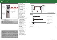
double swing_4.cdr - Hansa
double swing_4.cdr - Hansa
double swing_4.cdr - Hansa

You also want an ePaper? Increase the reach of your titles
YUMPU automatically turns print PDFs into web optimized ePapers that Google loves.
Nice - <strong>Hansa</strong><br />
SWING GATE CONTROLLER<br />
SINGLE & DOUBLE<br />
13-01-09
Single & Double Swing Gate Controller<br />
Introduction:<br />
The controller board was designed to cate r for most of the basic requirements of sing<br />
le and <strong>double</strong> <strong>swing</strong> gates.<br />
It requires very little intervention on the part of the installers as a set of pre-defined pa rameters may b e selected<br />
at installation time. The installer can choose bet ween 6 different type os installation.<br />
The different options and defaul t value s are sh own in the tables below.<br />
Installation , alignment and self learning cycle<br />
The installation is very simple! An initial learning cycle automatically checks limit switches position , measures<br />
open / close timing and maximum current overload . All the installer has to do is to follow thesimple instructions<br />
on page 2.<br />
Furthermore during normal it is possible to supervise different functions / levels by changing the display mode.<br />
All information is be displayed using a 7 Segment digit and an 8 Led Array<br />
1 8<br />
The factory default values (before a learning cycle ) are:<br />
The factory default input options are as follows<br />
NORMAL CYCLE PARAMETERS<br />
VALUES<br />
INPUTS<br />
ACTIVATION<br />
OPEN / CLOSE RUN TIME<br />
STAY-OPEN TIME OUT (time before closing)<br />
LIP TIME (delay between first and second motor)<br />
MAXIMUM CURRENT ALLOWED MOTOR 1<br />
MAXIMUM CURRENT ALLOWED MOTOR 2<br />
20 SEC<br />
5 SEC<br />
2 SEC<br />
10 A<br />
10A<br />
“OPEN” LIMIT SWITCH GATE 1<br />
“CLOSED” LIMIT SWITCH GATE 1<br />
“OPEN” LIMIT SWITCH GATE 2<br />
“CLOSED” LIMIT SWITCH GATE 2<br />
ON CLOSING<br />
ON CLOSING<br />
ON CLOSING<br />
ON CLOSING<br />
COURTESY LIGHT DURATION<br />
4 MINUTES<br />
INFRARED SAFETY BEAM<br />
ON CLOSING<br />
TRIGGER 3 (PEDESTRIAN)<br />
ON CLOSING<br />
PEDESTRIAN CYCLE PARAMETERS<br />
OPEN / CLOSE RUN TIME FOR PEDESTRIAN CYCLE<br />
STAY-OPEN TIME OUT FOR PEDESTRIAN CYCLE<br />
VALUES<br />
5 SEC<br />
2 SEC<br />
TRIGGER2 (CONDOMINIUM)<br />
TRIGGER 1 TO OPEN GATE /AUTO-OVERRIDE<br />
TRIGGER 1 TO CLOSE GATE<br />
ON CLOSING<br />
ON OPENING<br />
ON CLOSING<br />
COURTESY LIGHT TIME (IF SELECTED -DIPSW 3)<br />
30 SEC<br />
COURTESY LIGHT / LOCK OPERATION<br />
A general purpose relay provides the facility for<br />
controlling either a courtesy light or a lock.<br />
Furthermore the installer may chose between<br />
a striker lock or a magnetic lock operation.<br />
The relay contacts are voltage free and are rated at :<br />
10A / 220V AC or 10A / 28V DC<br />
BUZZER OPERATION<br />
The controller has also the facility of warning the<br />
user before any opening or closing cycle by means<br />
of a buzzer mounted on board.<br />
The buzzer also indicates different “error” conditions<br />
with a differentnumber of beeps.<br />
BUZZER<br />
N/C<br />
N/O<br />
COM<br />
(-) 0V<br />
+12V<br />
light/lock<br />
relay<br />
NICE-HANSA 386Bxx<br />
P-1<br />
X361-mami
IMPORTANT!!:<br />
WHEN APPLYING POWER FOR THE FIRST TIME THE UNIT WILL FLASH THE LEDS (4 AT THE TIME)<br />
TO INDICATE THAT THE SYSTEM HAS TO “LEARN” THE OPEN AND CLOSE CYCLE AND STORE IT IN MEMORY.<br />
CAREFULLY FOLLOW THE 3 STEPS DESCRIBED BELOW FOR A CORRECT INITIAL SETUP<br />
STEP 1- SELECTING THE INSTALLATION TYPE<br />
1- Ensure Power is OFF<br />
2- Select the installation Type using<br />
dipswitches 1,2 and 3 (see Table1)<br />
3- Hold button “A” while..<br />
4- Applying power<br />
5- Wait for LED’s to flash<br />
6- Remove power<br />
NOTE: After this operation<br />
A new learn cycle is required !!<br />
3<br />
2<br />
(Table1)<br />
OPTIONS / PRESET NO.<br />
Maximum CURRENT Detection<br />
Clutch SENSOR Detection<br />
dip switch settings<br />
(only 1,2 and 3 shown) 1 2 3 1 2 3<br />
These are the different options for the different presets<br />
TWO MOTORS ONE MOTOR<br />
0 1 2 3 4 5<br />
X X X X<br />
X X X<br />
X<br />
ON<br />
ON<br />
ON<br />
1 2 3<br />
ON<br />
1 2 3<br />
ON<br />
1 2 3<br />
ON<br />
1 2 3<br />
8<br />
1<br />
A<br />
Dipswitch<br />
1 2 3 4 5 6 7 8<br />
ON<br />
2<br />
1 8<br />
5<br />
+<br />
-<br />
30A<br />
1&4<br />
STEP 2 -INITIAL AUTOMATIC SETUP USING A LEARNING CYCLE<br />
LOOSEN THE CONNECTING ARM SCREWS ON THE SHAFT OF THE 2 MOTORS<br />
1- Apply Power and wait for the “0” to appear on the display (see page 3)<br />
2- Move dip-switch 2 to ON (all other switches= off)<br />
3- Hold button “A” until leds flash and P-R-G-1- is displayed<br />
Note: if a “b” appears on the display the battery voltage is too low!!<br />
4- Using Trigger 1 close gate 1 until the “close “ limit sw is activated<br />
5- Using Trigger 2 close gate 2 until the “close “ limit sw is activated<br />
Note that releasing the button will invert the direction<br />
6- ENSURE THE GATES ARE CLOSED THEN TIGHTEN THE<br />
TWO SCREWS ON THE SHAFT<br />
7- Wait for the number of the motor you want to start first<br />
to appear on the display and press the “A” button.<br />
8- The motors will individually open and close at Low speed<br />
(to test the limit switches)<br />
9- The motors will individually open and close at Full speed<br />
( to measure the time and the overload)<br />
10- the display will show R-D-Y and<br />
11- !!! move dip sw 2 back to OFF !!!<br />
12- You are now ready to operate the gate normally<br />
M2<br />
1 & 6<br />
M1<br />
( )<br />
7<br />
5<br />
4<br />
1<br />
8<br />
TRIGGER 1<br />
A<br />
TRIGGER 2<br />
1 2 3 4 5 6 7 8<br />
Dipswitch<br />
ON<br />
3 & 7<br />
NICE-HANSA-386B21<br />
2 & 11<br />
BUZZER<br />
STEP 3 - SETTING THE “STAY-OPEN” TIME<br />
1- Move dip-switch 3 to ON (all other switches= off)<br />
2- Hold button “A” until leds flash and P-R-G-2- is displayed<br />
3- count the seconds you would like the gate to stay open<br />
(the least significant digit in seconds is shown on the display<br />
4- Hold button “A” until leds flash and R-D-Y is displayed followed by<br />
- the time is stored in memory-<br />
5- !!! move dip sw 3 back to OFF !!!<br />
P-2<br />
3<br />
8<br />
1<br />
A<br />
1 2 3 4 5 6 7 8<br />
Dipswitch<br />
ON<br />
2 & 4<br />
1<br />
X361-mami
Power up sequence<br />
WHEN POWER IS APPLIED THE GATE , IF OPEN, WILL AUTOMATICALLY CLOSE AT A LOW SPEED.<br />
NORMAL OPERATION:<br />
At power up the system will automatically step through :<br />
1= LED TEST (all led’s lit up simultaneously and in sequence)<br />
1 8<br />
All On<br />
In sequence<br />
1 8<br />
2= DISPLAY DEFAULT NO (FLASHING 5TIMES)<br />
3= SHOW UTILITY LEDS<br />
Utilities LED’S<br />
ALARM CONDITION<br />
1 8 1 8<br />
BATTERY LOW<br />
MAXIMUM CURRENTM1<br />
MAXIMUM CURRENT M2<br />
CLUTCH SENSOR M1<br />
CLUTCH SENSOR M2<br />
IMPORTANT NOTE: when the battery voltage reaches 23.6 Volts the control board<br />
will automatically shut down and turn the battery-low LED on<br />
Display modes SWING GATE<br />
While in CLOSED POSITION it is possible to select different type of data to be displayed on the 8 led array<br />
Pressing button "A" will cycle the display through:<br />
- = NO DISPLAY<br />
1 = DISPLAY CURRENT OF MOTOR 1<br />
2 = DISPLAY CURRENT OF MOTOR 2<br />
U = DISPLAY CURRENT UTILITIES LEDS STATUS (EMERGENCY STOPS)<br />
b = DISPLAY BATTERY LEVEL<br />
O = SHOW DIP SWITCH READING BY CPU<br />
i = SHOW INPUTS READING BY CPU<br />
No display<br />
display current<br />
consumption M1<br />
display current<br />
consumption M2<br />
Utilities LED’S<br />
24v Battery<br />
voltage level<br />
Dip-switch<br />
reading<br />
Inputs<br />
reading<br />
1 8<br />
1 8<br />
low<br />
high<br />
1 8<br />
low<br />
high<br />
1 8<br />
SYSTEM LOCKED OUT<br />
BATTERY LOW<br />
TRIGGER 2 JAMMED<br />
TRIGGER 1 JAMMED<br />
MAX CURRENT M1<br />
MAX CURRENT M2<br />
CLUTCH SENSOR M1<br />
CLUTCH SENSOR M2<br />
1 8<br />
low<br />
ok<br />
1 8<br />
1 8<br />
L.S. open M2<br />
L.S. close M2<br />
L.S. open M1<br />
L.S. close M1<br />
Beam<br />
Pedestrian<br />
Trig. 2<br />
Trig. 1<br />
Dip-Switch option selection<br />
Different options can be changed using the 8 slide switches (8 way DIP SWITCH) mounted on board.<br />
NOTE: most options become selectable only when the gate is in the “closed” position.<br />
For security reason during the pedestrian cycle the safety beam is INACTIVE!!! ( only the overload is active)<br />
SWITCH<br />
NO.<br />
8<br />
7<br />
FUNCTION<br />
MAGNETIC/STRIKE<br />
LOCK SELECT<br />
FORCE<br />
“STAY-OPEN”<br />
DESCRIPTION OF FUNCTION<br />
( DIP-SWITCH 4 MUST BE ON)<br />
When ON the LOCK RELAY will operate for the duration of the cycle<br />
When OFF the strike lock will operate for 1 Sec before opening<br />
When ON, if TRIGGER 1 is held in for longer then 3 seconds the gate will<br />
open and stay open even if the AUTO-CLOSURE SWITCH 6 is ON<br />
6<br />
5<br />
4<br />
ENABLE<br />
“AUTOCLOSURE”<br />
A.S.A.P.<br />
“AUTOCLOSURE”<br />
“LOCK SELECT” /<br />
COURTESY LIGHT<br />
When ON, the gates will AUTOMATICALLY close after the preprogrammed<br />
“STAY-OPEN” time has elapsed<br />
When ON, the gates will AUTOMATICALLY close after the SAFETY BEAM<br />
has been interrupted ( will open while beam is broken but will re-close<br />
immediately if beam is clear - If beam is not broken will close after 5 sec.<br />
When ON the relay will activate a lock for 1 sec before the gate opens<br />
When OFF the relay will activate the courtesy light for 4 minutes<br />
ON<br />
1 2 3 4 5 6 7 8<br />
Magnetic Lock Select<br />
Allow OVER-RIDE of Autoclosure<br />
Enable AUTOCLOSURE<br />
Enable A.S.A.P.<br />
Enable LOCK Operation<br />
Set “Stay-open Time”<br />
Enter Initial Settings<br />
Enable GATE LIP<br />
3<br />
PROGRAM<br />
“STAY-OPEN” TIME<br />
If ON while pressing button “A” - program the duration the gates will<br />
stay open before closing automatically (if auto-close is selected)<br />
2<br />
1<br />
ENTER INITIAL<br />
MOTOR SETUP<br />
“LIP” FUNCTION<br />
If ON while pressing button “A” - test and learn opening and closing time<br />
- measure current overload for each motor<br />
When ON, one of the two gates will open and close 2 seconds earlier<br />
then the other - the FIRST motor is selected during the initial setup (pag...)<br />
P-3<br />
X361-mami
what is what....<br />
Optional on board<br />
remote control Receiver<br />
Unswitched + 12V<br />
Power to RX<br />
Resettable fuse for<br />
auxiliary 12V (1Amax)<br />
ANT<br />
ANT(GND)<br />
RX +12V<br />
RX serial data<br />
RX 0V<br />
+12V<br />
Auxiliary 12V Power<br />
500 mA maximum Voltage free contacts for either<br />
- 220v ac courtesy light or<br />
- Electric lock<br />
0V<br />
N/C<br />
COM<br />
N/O<br />
M2<br />
M1<br />
16 17 18 19 20 21 22 23 24 25 26 27 28 29<br />
POWER IN<br />
30A main<br />
Fuse<br />
-<br />
+<br />
30A<br />
M2 MOSFET<br />
M2<br />
0 1 2 3<br />
Overload<br />
adjust<br />
M1<br />
0 1 2 3<br />
Overload<br />
adjust<br />
light/lock<br />
relay<br />
M1 MOSFET<br />
B<br />
T<br />
R<br />
A<br />
1 2 3 4 5 6 7 8<br />
1 8<br />
Dipswitch<br />
INPUT STATUS LEDS<br />
PCB version number<br />
Current Overload adjust<br />
0 1 2 3<br />
CLOSE<br />
RELAY<br />
20A M2<br />
Fuse<br />
M2 M2 M1 M1<br />
20A<br />
( Motors 1 and 2)<br />
0 1 2 3 0 1 2 3 0 1 2 3<br />
OPEN<br />
RELAY<br />
M2<br />
CLOSE<br />
RELAY<br />
M1<br />
connections<br />
to motors<br />
20A<br />
OPEN<br />
RELAY<br />
20A M1<br />
Fuse<br />
-<br />
Connections for<br />
extended status indication<br />
1 2 3 4 5 6 7 8 9 10 11 12 13<br />
+<br />
0V<br />
LS 2 OP<br />
LS 2 CL<br />
LS 1 OP<br />
LS 1 CL<br />
Inputs description<br />
Earth<br />
BEAM<br />
PED<br />
TRIG 2<br />
TRIG 1<br />
0V<br />
NICE-HANSA- 386B??<br />
LS 2 OP<br />
BUZZER<br />
LS 2 CL<br />
Magnetic<br />
limit switches<br />
connections<br />
LS 1 OP<br />
LS 1 CL<br />
BEAM<br />
PED<br />
TRIG 2<br />
TRIG 1<br />
LIGHTENING PROTECTION<br />
BOARD (OPTIONAL)<br />
DISABLE<br />
maximum<br />
current<br />
overload<br />
detection<br />
minimum<br />
current<br />
overload<br />
detection.<br />
FACTORY<br />
DEFAULT<br />
medium<br />
current<br />
overload<br />
detection<br />
high<br />
current<br />
overload<br />
detection<br />
EXTENDED STATUS INDICATIONS:<br />
with Gate moving:<br />
- Steady on = GATE OPEN<br />
- One pulse per second = GATE OPENING<br />
LIGHTNING PROTECTION BOARD<br />
This board provides extra lightning protection on each of the<br />
8 inputs for areas where lightning strikes are common.<br />
The board is fitted over the existing input connector.<br />
gas arrestors<br />
- Two pulses per second = GATE CLOSING<br />
with Gate closed:<br />
- Five pulses per second = safety beam interrupted<br />
- Permanently OFF = battery fully charged/ all normal<br />
- Slight flickering = battery low<br />
new connections<br />
Earth<br />
BUZZER STATUS INDICATIONS:<br />
1 BEEP = Maximum current M1<br />
3 BEEPS = Clutch Sensor M1<br />
2 BEEPS = Maximum current M2 4 BEEPS = Clutch Sensor M2<br />
P-4 X361-mami
M1<br />
M2<br />
N/O<br />
N/C<br />
COM<br />
0V<br />
+12V<br />
RX 0V<br />
RX +12V<br />
RX serial data<br />
ANT(GND)<br />
ANT<br />
16 17 18 19 20 21 22 23 24 25 26 27 28 29<br />
1 2 3 4 5 6 7 8<br />
A<br />
B<br />
T<br />
light/lock<br />
relay<br />
R<br />
1 8<br />
M1 MOSFET<br />
M1<br />
0 1 2 3<br />
0V<br />
Overload<br />
adjust<br />
+12V<br />
GENERIC<br />
RADIO<br />
RECEIVER<br />
Dipswitch<br />
NICE-HANSA- 386B??<br />
OPEN<br />
RELAY<br />
CLOSE<br />
RELAY<br />
BUZZER<br />
Loop detector<br />
M1 M1<br />
1 2 3 4 5 6 7 8 9 10 11 12 13<br />
+<br />
-<br />
20A<br />
Earth<br />
TRIGG1<br />
0V<br />
TRIGG1<br />
TRIGG2<br />
PED<br />
BEAM<br />
LS CL 1<br />
LS OP 1<br />
BUZZER<br />
TRIGG2<br />
PED<br />
LS OP<br />
LS CL<br />
CLUTCH<br />
0V<br />
Remote led<br />
BEAMCELL<br />
-<br />
+<br />
POWER IN<br />
30A<br />
Connectin a<br />
Single Swing<br />
gate controller<br />
P-5<br />
X361-mami
M1<br />
M2<br />
N/O<br />
N/C<br />
COM<br />
0V<br />
+12V<br />
RX 0V<br />
RX +12V<br />
RX serial data<br />
ANT(GND)<br />
ANT<br />
16 17 18 19 20 21 22 23 24 25 26 27 28 29<br />
1 2 3 4 5 6 7 8<br />
A<br />
B<br />
GENERIC<br />
RADIO<br />
RECEIVER<br />
0V<br />
+12V<br />
Loop detector<br />
Dipswitch<br />
T<br />
light/lock<br />
relay<br />
R<br />
-<br />
+<br />
1 8<br />
M1 MOSFET<br />
M1<br />
0 1 2 3<br />
M2<br />
0 1 2 3<br />
30A<br />
Overload<br />
adjust<br />
Overload<br />
adjust<br />
M2 MOSFET<br />
NICE-HANSA- 386B??<br />
OPEN<br />
RELAY<br />
CLOSE<br />
RELAY<br />
OPEN<br />
RELAY<br />
CLOSE<br />
RELAY<br />
BUZZER<br />
M2 M2 M1 M1<br />
1 2 3 4 5 6 7 8 9 10 11 12 13<br />
+<br />
-<br />
20A 20A<br />
Earth<br />
TRIGG1<br />
0V<br />
TRIGG1<br />
TRIGG2<br />
PED<br />
BEAM<br />
LS CL 1<br />
LS OP 1<br />
TRIGG2<br />
PED<br />
LS OP<br />
LS CL<br />
SENSOR<br />
0V<br />
LS OP<br />
LS CL<br />
SENSOR<br />
0V<br />
Remote led<br />
BEAMCELL<br />
M1<br />
M2<br />
Connecting a Double Swing gate controller<br />
P-6<br />
X361-mami
PROGRAMMING THE RADIO REMOTE CONTROL CODES<br />
The controller has the capability of storing the codes of up to 100 remote cotrols<br />
STORING THE REMOTE CONTROLS IS VERY EASY<br />
1- ensure that the gate is in the closed condition.<br />
2- set dip-switches 3 and 4 to ON<br />
3- hold button A until “ P r g r c ” is displayed<br />
4- using trigger 1 (UP) and trigger 2(DOWN) select the location in<br />
memory where you want to store the new remote control code<br />
or<br />
hold trigger 1 for longer then 2 seconds to access to the next<br />
free location in memory (the new location will be displayed)<br />
5- press and hold button A while transmitting with the new remote<br />
control. Once stored the display will show<br />
6- if you require to store more then 1 transmitter<br />
repeat sequence from point 4<br />
4<br />
1<br />
8<br />
A<br />
1 2 3 4 5 6 7 8<br />
Dipswitch<br />
ON<br />
3 & 5<br />
2 & 7<br />
7- to exit programming simply switch dipswitches 3 and 4 to OFF<br />
REMOTE CONTROLL BUTTONS:<br />
- button 1 will activate TRIGGER 1<br />
- button 2 will activate the PEDESTRIAN trigger<br />
- button 3 will lock the Gate ( disable all activations except radio)<br />
- buttons 1 and 3 will unlock the gate (enable all triggers)<br />
- button 4 will activate the courtesy light<br />
4<br />
TRIGGER 2<br />
TRIGGER 1<br />
NICE-HANSA-386B21<br />
BUZZER<br />
THINGS TO REMEMBER:<br />
BEFORE THE LEARN CYCLE:<br />
When applying power for the first time the unit will flash the leds (4 at the time)<br />
this indicates that the system has to “learn” the open and close cycle and store it in memory.<br />
During the learn cycle triggers 1 and 2 buttons will CLOSE the gate . EACH TIME THE BUTTONS ARE Released<br />
the direction of the motors is inverted<br />
If at power up a “b” appears on the display the battery voltage is too low to do the “learn” cycle.<br />
The learn cycle must be performed with FULLY CHARGED BATTERY for a correct current<br />
measurement<br />
DURING THE LEARN CYCLE:<br />
During the full speed procedure of the learning cycle it is possible to change the “slow-down “ points of the gate<br />
while opening and while closing. To do this:<br />
1 - Press Trigger one to start the full speed cycle<br />
2 - as the gate approaches the open position press button A<br />
AFTER THE LEARN CYCLE:<br />
when power is applied or AFTER A MAINS FAILURE the gate , if open, will close automatically at low speed.<br />
When the battery voltage reaches 23.6 volts the control board will automatically shut down and turn the<br />
battery-low led on . No operation is possible under this condition<br />
During the pedestrian cycle the safety beam is not implemented and only the overload safety is active
NOTES:<br />
Nice - <strong>Hansa</strong>