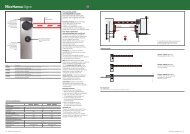
double swing_4.cdr - Hansa
double swing_4.cdr - Hansa
double swing_4.cdr - Hansa

You also want an ePaper? Increase the reach of your titles
YUMPU automatically turns print PDFs into web optimized ePapers that Google loves.
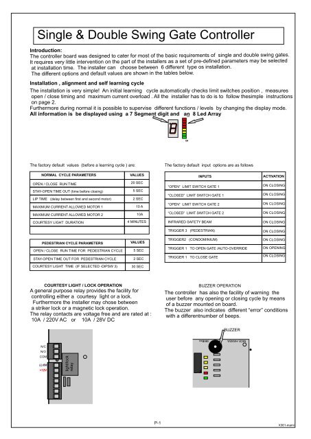
Single & Double Swing Gate Controller<br />
Introduction:<br />
The controller board was designed to cate r for most of the basic requirements of sing<br />
le and <strong>double</strong> <strong>swing</strong> gates.<br />
It requires very little intervention on the part of the installers as a set of pre-defined pa rameters may b e selected<br />
at installation time. The installer can choose bet ween 6 different type os installation.<br />
The different options and defaul t value s are sh own in the tables below.<br />
Installation , alignment and self learning cycle<br />
The installation is very simple! An initial learning cycle automatically checks limit switches position , measures<br />
open / close timing and maximum current overload . All the installer has to do is to follow thesimple instructions<br />
on page 2.<br />
Furthermore during normal it is possible to supervise different functions / levels by changing the display mode.<br />
All information is be displayed using a 7 Segment digit and an 8 Led Array<br />
1 8<br />
The factory default values (before a learning cycle ) are:<br />
The factory default input options are as follows<br />
NORMAL CYCLE PARAMETERS<br />
VALUES<br />
INPUTS<br />
ACTIVATION<br />
OPEN / CLOSE RUN TIME<br />
STAY-OPEN TIME OUT (time before closing)<br />
LIP TIME (delay between first and second motor)<br />
MAXIMUM CURRENT ALLOWED MOTOR 1<br />
MAXIMUM CURRENT ALLOWED MOTOR 2<br />
20 SEC<br />
5 SEC<br />
2 SEC<br />
10 A<br />
10A<br />
“OPEN” LIMIT SWITCH GATE 1<br />
“CLOSED” LIMIT SWITCH GATE 1<br />
“OPEN” LIMIT SWITCH GATE 2<br />
“CLOSED” LIMIT SWITCH GATE 2<br />
ON CLOSING<br />
ON CLOSING<br />
ON CLOSING<br />
ON CLOSING<br />
COURTESY LIGHT DURATION<br />
4 MINUTES<br />
INFRARED SAFETY BEAM<br />
ON CLOSING<br />
TRIGGER 3 (PEDESTRIAN)<br />
ON CLOSING<br />
PEDESTRIAN CYCLE PARAMETERS<br />
OPEN / CLOSE RUN TIME FOR PEDESTRIAN CYCLE<br />
STAY-OPEN TIME OUT FOR PEDESTRIAN CYCLE<br />
VALUES<br />
5 SEC<br />
2 SEC<br />
TRIGGER2 (CONDOMINIUM)<br />
TRIGGER 1 TO OPEN GATE /AUTO-OVERRIDE<br />
TRIGGER 1 TO CLOSE GATE<br />
ON CLOSING<br />
ON OPENING<br />
ON CLOSING<br />
COURTESY LIGHT TIME (IF SELECTED -DIPSW 3)<br />
30 SEC<br />
COURTESY LIGHT / LOCK OPERATION<br />
A general purpose relay provides the facility for<br />
controlling either a courtesy light or a lock.<br />
Furthermore the installer may chose between<br />
a striker lock or a magnetic lock operation.<br />
The relay contacts are voltage free and are rated at :<br />
10A / 220V AC or 10A / 28V DC<br />
BUZZER OPERATION<br />
The controller has also the facility of warning the<br />
user before any opening or closing cycle by means<br />
of a buzzer mounted on board.<br />
The buzzer also indicates different “error” conditions<br />
with a differentnumber of beeps.<br />
BUZZER<br />
N/C<br />
N/O<br />
COM<br />
(-) 0V<br />
+12V<br />
light/lock<br />
relay<br />
NICE-HANSA 386Bxx<br />
P-1<br />
X361-mami