double swing_4.cdr - Hansa
double swing_4.cdr - Hansa
double swing_4.cdr - Hansa

You also want an ePaper? Increase the reach of your titles
YUMPU automatically turns print PDFs into web optimized ePapers that Google loves.
IMPORTANT!!:<br />
WHEN APPLYING POWER FOR THE FIRST TIME THE UNIT WILL FLASH THE LEDS (4 AT THE TIME)<br />
TO INDICATE THAT THE SYSTEM HAS TO “LEARN” THE OPEN AND CLOSE CYCLE AND STORE IT IN MEMORY.<br />
CAREFULLY FOLLOW THE 3 STEPS DESCRIBED BELOW FOR A CORRECT INITIAL SETUP<br />
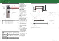
STEP 1- SELECTING THE INSTALLATION TYPE<br />
1- Ensure Power is OFF<br />
2- Select the installation Type using<br />
dipswitches 1,2 and 3 (see Table1)<br />
3- Hold button “A” while..<br />
4- Applying power<br />
5- Wait for LED’s to flash<br />
6- Remove power<br />
NOTE: After this operation<br />
A new learn cycle is required !!<br />
3<br />
2<br />
(Table1)<br />
OPTIONS / PRESET NO.<br />
Maximum CURRENT Detection<br />
Clutch SENSOR Detection<br />
dip switch settings<br />
(only 1,2 and 3 shown) 1 2 3 1 2 3<br />
These are the different options for the different presets<br />
TWO MOTORS ONE MOTOR<br />
0 1 2 3 4 5<br />
X X X X<br />
X X X<br />
X<br />
ON<br />
ON<br />
ON<br />
1 2 3<br />
ON<br />
1 2 3<br />
ON<br />
1 2 3<br />
ON<br />
1 2 3<br />
8<br />
1<br />
A<br />
Dipswitch<br />
1 2 3 4 5 6 7 8<br />
ON<br />
2<br />
1 8<br />
5<br />
+<br />
-<br />
30A<br />
1&4<br />
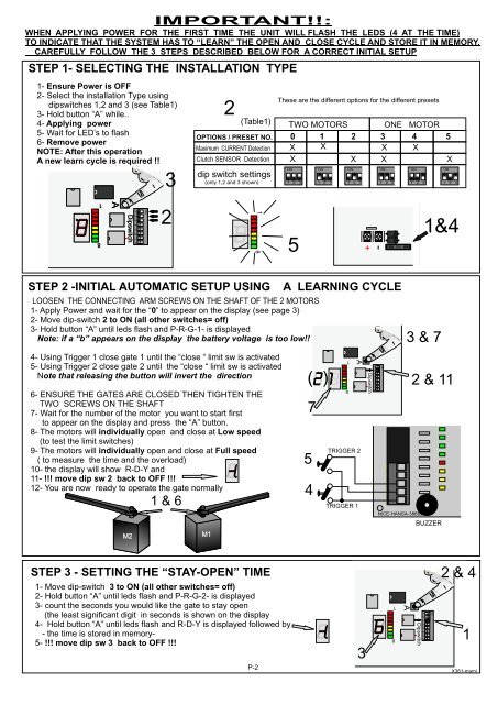
STEP 2 -INITIAL AUTOMATIC SETUP USING A LEARNING CYCLE<br />
LOOSEN THE CONNECTING ARM SCREWS ON THE SHAFT OF THE 2 MOTORS<br />
1- Apply Power and wait for the “0” to appear on the display (see page 3)<br />
2- Move dip-switch 2 to ON (all other switches= off)<br />
3- Hold button “A” until leds flash and P-R-G-1- is displayed<br />
Note: if a “b” appears on the display the battery voltage is too low!!<br />
4- Using Trigger 1 close gate 1 until the “close “ limit sw is activated<br />
5- Using Trigger 2 close gate 2 until the “close “ limit sw is activated<br />
Note that releasing the button will invert the direction<br />
6- ENSURE THE GATES ARE CLOSED THEN TIGHTEN THE<br />
TWO SCREWS ON THE SHAFT<br />
7- Wait for the number of the motor you want to start first<br />
to appear on the display and press the “A” button.<br />
8- The motors will individually open and close at Low speed<br />
(to test the limit switches)<br />
9- The motors will individually open and close at Full speed<br />
( to measure the time and the overload)<br />
10- the display will show R-D-Y and<br />
11- !!! move dip sw 2 back to OFF !!!<br />
12- You are now ready to operate the gate normally<br />
M2<br />
1 & 6<br />
M1<br />
( )<br />
7<br />
5<br />
4<br />
1<br />
8<br />
TRIGGER 1<br />
A<br />
TRIGGER 2<br />
1 2 3 4 5 6 7 8<br />
Dipswitch<br />
ON<br />
3 & 7<br />
NICE-HANSA-386B21<br />
2 & 11<br />
BUZZER<br />
STEP 3 - SETTING THE “STAY-OPEN” TIME<br />
1- Move dip-switch 3 to ON (all other switches= off)<br />
2- Hold button “A” until leds flash and P-R-G-2- is displayed<br />
3- count the seconds you would like the gate to stay open<br />
(the least significant digit in seconds is shown on the display<br />
4- Hold button “A” until leds flash and R-D-Y is displayed followed by<br />
- the time is stored in memory-<br />
5- !!! move dip sw 3 back to OFF !!!<br />
P-2<br />
3<br />
8<br />
1<br />
A<br />
1 2 3 4 5 6 7 8<br />
Dipswitch<br />
ON<br />
2 & 4<br />
1<br />
X361-mami