double swing_4.cdr - Hansa
double swing_4.cdr - Hansa
double swing_4.cdr - Hansa

Create successful ePaper yourself
Turn your PDF publications into a flip-book with our unique Google optimized e-Paper software.
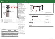
Power up sequence<br />
WHEN POWER IS APPLIED THE GATE , IF OPEN, WILL AUTOMATICALLY CLOSE AT A LOW SPEED.<br />
NORMAL OPERATION:<br />
At power up the system will automatically step through :<br />
1= LED TEST (all led’s lit up simultaneously and in sequence)<br />
1 8<br />
All On<br />
In sequence<br />
1 8<br />
2= DISPLAY DEFAULT NO (FLASHING 5TIMES)<br />
3= SHOW UTILITY LEDS<br />
Utilities LED’S<br />
ALARM CONDITION<br />
1 8 1 8<br />
BATTERY LOW<br />
MAXIMUM CURRENTM1<br />
MAXIMUM CURRENT M2<br />
CLUTCH SENSOR M1<br />
CLUTCH SENSOR M2<br />
IMPORTANT NOTE: when the battery voltage reaches 23.6 Volts the control board<br />
will automatically shut down and turn the battery-low LED on<br />
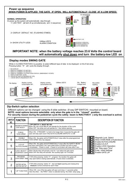
Display modes SWING GATE<br />
While in CLOSED POSITION it is possible to select different type of data to be displayed on the 8 led array<br />
Pressing button "A" will cycle the display through:<br />
- = NO DISPLAY<br />
1 = DISPLAY CURRENT OF MOTOR 1<br />
2 = DISPLAY CURRENT OF MOTOR 2<br />
U = DISPLAY CURRENT UTILITIES LEDS STATUS (EMERGENCY STOPS)<br />
b = DISPLAY BATTERY LEVEL<br />
O = SHOW DIP SWITCH READING BY CPU<br />
i = SHOW INPUTS READING BY CPU<br />
No display<br />
display current<br />
consumption M1<br />
display current<br />
consumption M2<br />
Utilities LED’S<br />
24v Battery<br />
voltage level<br />
Dip-switch<br />
reading<br />
Inputs<br />
reading<br />
1 8<br />
1 8<br />
low<br />
high<br />
1 8<br />
low<br />
high<br />
1 8<br />
SYSTEM LOCKED OUT<br />
BATTERY LOW<br />
TRIGGER 2 JAMMED<br />
TRIGGER 1 JAMMED<br />
MAX CURRENT M1<br />
MAX CURRENT M2<br />
CLUTCH SENSOR M1<br />
CLUTCH SENSOR M2<br />
1 8<br />
low<br />
ok<br />
1 8<br />
1 8<br />
L.S. open M2<br />
L.S. close M2<br />
L.S. open M1<br />
L.S. close M1<br />
Beam<br />
Pedestrian<br />
Trig. 2<br />
Trig. 1<br />
Dip-Switch option selection<br />
Different options can be changed using the 8 slide switches (8 way DIP SWITCH) mounted on board.<br />
NOTE: most options become selectable only when the gate is in the “closed” position.<br />
For security reason during the pedestrian cycle the safety beam is INACTIVE!!! ( only the overload is active)<br />
SWITCH<br />
NO.<br />
8<br />
7<br />
FUNCTION<br />
MAGNETIC/STRIKE<br />
LOCK SELECT<br />
FORCE<br />
“STAY-OPEN”<br />
DESCRIPTION OF FUNCTION<br />
( DIP-SWITCH 4 MUST BE ON)<br />
When ON the LOCK RELAY will operate for the duration of the cycle<br />
When OFF the strike lock will operate for 1 Sec before opening<br />
When ON, if TRIGGER 1 is held in for longer then 3 seconds the gate will<br />
open and stay open even if the AUTO-CLOSURE SWITCH 6 is ON<br />
6<br />
5<br />
4<br />
ENABLE<br />
“AUTOCLOSURE”<br />
A.S.A.P.<br />
“AUTOCLOSURE”<br />
“LOCK SELECT” /<br />
COURTESY LIGHT<br />
When ON, the gates will AUTOMATICALLY close after the preprogrammed<br />
“STAY-OPEN” time has elapsed<br />
When ON, the gates will AUTOMATICALLY close after the SAFETY BEAM<br />
has been interrupted ( will open while beam is broken but will re-close<br />
immediately if beam is clear - If beam is not broken will close after 5 sec.<br />
When ON the relay will activate a lock for 1 sec before the gate opens<br />
When OFF the relay will activate the courtesy light for 4 minutes<br />
ON<br />
1 2 3 4 5 6 7 8<br />
Magnetic Lock Select<br />
Allow OVER-RIDE of Autoclosure<br />
Enable AUTOCLOSURE<br />
Enable A.S.A.P.<br />
Enable LOCK Operation<br />
Set “Stay-open Time”<br />
Enter Initial Settings<br />
Enable GATE LIP<br />
3<br />
PROGRAM<br />
“STAY-OPEN” TIME<br />
If ON while pressing button “A” - program the duration the gates will<br />
stay open before closing automatically (if auto-close is selected)<br />
2<br />
1<br />
ENTER INITIAL<br />
MOTOR SETUP<br />
“LIP” FUNCTION<br />
If ON while pressing button “A” - test and learn opening and closing time<br />
- measure current overload for each motor<br />
When ON, one of the two gates will open and close 2 seconds earlier<br />
then the other - the FIRST motor is selected during the initial setup (pag...)<br />
P-3<br />
X361-mami