Hydrometer INT6 Energy Calculator - hsa-asia.com
Hydrometer INT6 Energy Calculator - hsa-asia.com
Hydrometer INT6 Energy Calculator - hsa-asia.com

Create successful ePaper yourself
Turn your PDF publications into a flip-book with our unique Google optimized e-Paper software.
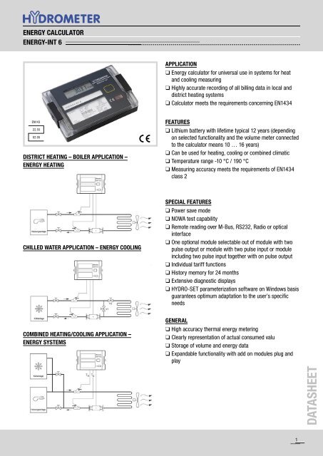
ENERGY CALCULATOR<br />
ENERGY-INT 6<br />
APPLICATION<br />
❑ <strong>Energy</strong> calculator for universal use in systems for heat<br />
and cooling measuring<br />
❑ Highly accurate recording of all billing data in local and<br />
district heating systems<br />
❑ <strong>Calculator</strong> meets the requirements concerning EN1434<br />
EN143<br />
22.55<br />
02.05<br />
DISTRICT HEATING – BOILER APPLICATION –<br />
ENERGY HEATING<br />
FEATURES<br />
❑ Lithium battery with lifetime typical 12 years (depending<br />
on selected functionality and the volume meter connected<br />
to the calculator means 10 … 16 years)<br />
❑ Can be used for heating, cooling or <strong>com</strong>bined climatic<br />
❑ Temperature range -10 °C / 190 °C<br />
❑ Measuring accuracy meets the requirements of EN1434<br />
class 2<br />
CHILLED WATER APPLICATION – ENERGY COOLING<br />
SPECIAL FEATURES<br />
❑ Power save mode<br />
❑ NOWA test capability<br />
❑ Remote reading over M-Bus, RS232, Radio or optical<br />
interface<br />
❑ One optional module selectable out of module with two<br />
pulse output or module with two pulse input or module<br />
including two pulse input together with on pulse output<br />
❑ Individual tariff functions<br />
❑ History memory for 24 months<br />
❑ Extensive diagnostic displays<br />
❑ HYDRO-SET parameterization software on Windows basis<br />
guarantees optimum adaptation to the user’s specific<br />
needs<br />
COMBINED HEATING/COOLING APPLICATION –<br />
ENERGY SYSTEMS<br />
GENERAL<br />
❑ High accuracy thermal energy metering<br />
❑ Clearly representation of actual consumed valu<br />
❑ Storage of volume and energy data<br />
❑ Expandable functionality with add on modules plug and<br />
play<br />
DATASHEET<br />
1
ENERGY CALCULATOR<br />
ENERGY-INT 6<br />
INTEGRATOR<br />
AThe integrator contains all the necessary circuits for<br />
recording the flow rate and temperature and for calculating,<br />
logging and displaying the data. The integrator housing can<br />
be mounted directly on the volume measuring <strong>com</strong>ponent or<br />
on the wall. At application with medium temperature above<br />
90°C or at temperatures T Wasser < T Umgebung the calculator has<br />
to be removed from the volume meter. The calculator can be<br />
conveniently read from a single-line 7-digit display with units<br />
and symbols. A pushbutton provides user-friendly control of<br />
the various display loops. All failures and faults are recorded<br />
automatically and shown on the LC display. To protect the<br />
reading data, all the relevant data are saved in a non-volatile<br />
memory (EEPROM). This memory saves the measured<br />
values, device parameters and types of error at regular<br />
intervals.<br />
SUPPLY VOLTAGE<br />
❑ Lithium battery 3.0 V DC (typ 12-year life)<br />
❑ Lithium battery 3.6 V DC at volume meter e.g. SHARKY<br />
model 473<br />
❑ Lithium battery 3.6 V DC at volume meter e.g. SHARKY<br />
model 087 (with 10-year life)<br />
❑ Mains unit 230VAC and 24VAC (on request)<br />
TEMPERATURE SENSORS<br />
Pairs of Pt 100 or Pt 500 temperature sensors<br />
(e.g. Ø 5.2 mm or Ø 6 mm) with 2-wire leads are used.<br />
INTERFACES<br />
ENERGY-INT 6 is equipped as standard with a ZVEI optical<br />
interface with the M-Bus protocol as per EN 1434. This<br />
interface is used, for example, for <strong>com</strong>munication with the<br />
HYDRO-SET parameterization software. The calculator<br />
features 2 slots for the modules. One slot for the function<br />
modules, and one for the <strong>com</strong>munication modules.<br />
The following <strong>com</strong>munication modules are available as<br />
options:<br />
❑ RS232 module<br />
❑ M-Bus module to EN 1434<br />
❑ RS 232 Modul<br />
The RS232 <strong>com</strong>munication module is a serial interface and<br />
permits data exchange with the calculator. For this purpose a<br />
special data cable is necessary.<br />
The M-Bus module is a serial interface for <strong>com</strong>munication<br />
with external devices (M-Bus Repeater) e.g. HYDRO-CEN-<br />
TER. A number of calculators can be connected to a control<br />
centre.<br />
The Radio module is an interface for <strong>com</strong>municate unidirectional<br />
over radio predefined data records. The protocol<br />
is send every 8 … 19 sec. For receiving there are different<br />
<strong>Hydrometer</strong> receiver available. The transmission protocol is<br />
editable by HYDRO-SET.<br />
PULSE INPUT<br />
Two pulse inputs are available. The pulse value and the unit<br />
is configurable for energy, water, gas or electrical meter by<br />
HYDRO-SET. The input frequency range is 0 – 8Hz with pulse-length<br />
≥ 10ms. Data are separate cumulated in different<br />
registers and are also stored on the two accounting day’s.<br />
The cable length to pulse input have to be less than 10m.<br />
COMBINED PULSE INPUT / OUTPUT<br />
Two pulse inputs <strong>com</strong>bined with one pulse output are<br />
available on one module. The pulse inputs are configurable<br />
with value and the unit by HYDRO-SET. The input frequency<br />
range is 0 – 8Hz with pulse-length ≥ 10ms. The pulse output<br />
is also programmable using the HYDRO-SET software. The<br />
“open collector” output is supplied with external power of<br />
3-30VDC and has an output frequency of ≤ 4Hz. The pulse<br />
width of the not potential separated pulses is 100-150ms.<br />
DATASHEET<br />
2
ENERGY CALCULATOR<br />
ENERGY-INT 6<br />
PULSE OUTPUT<br />
The calculator provides levels for two optional external pulse<br />
outputs, which can be freely programmed using the HYDRO-<br />
SET software. The outputs are “open collector” with external<br />
power supply of 3-30VDC and an output frequency of ≤ 4Hz.<br />
The pulse width of the potential separated pulses is 100-<br />
150ms.<br />
Possible pulse output values<br />
❑ <strong>Energy</strong> (standard setting)<br />
❑ Volume (standard setting)<br />
❑ Tariff energy 1<br />
❑ Tariff energy 2<br />
❑ Tariff condition 1, limit switch<br />
❑ Tariff condition 2, limit switch<br />
❑ <strong>Energy</strong> error<br />
❑ Volume error<br />
❑ Volume with specific resolution (0,1l / 1,0l / 10l / 100l) at<br />
3 digit after volume <strong>com</strong>ma<br />
❑ <strong>Energy</strong> with specific resolution (0,1 kWh) at 3 digit after<br />
volume <strong>com</strong>ma<br />
❑ Leakage detection (2 channel)<br />
MODULE COMBINATIONS<br />
The calculator has a group of extension modules for<br />
<strong>com</strong>munication and another group of extension modules for<br />
additional functionality. These modules are available first<br />
selected within the calculator, or for retrofitting in the field.<br />
One single function module as well as one single <strong>com</strong>munication<br />
module out of following modules is selectable.<br />
Function modules:<br />
❑ Pulse input module, 2 inputs<br />
❑ Pulse output module, 2 outputs<br />
❑ Combined pulse module 2 inputs, 1 output<br />
ACCESSORIES / SOFTWARE<br />
The HYDRO-SET parameterization software based on the<br />
M-Bus is a convenient tool for handling the calculator. It runs<br />
on Windows® 2000/XP and is used for<br />
❑ Configurating the functionality of the calculator<br />
❑ reading out different memories<br />
❑ printing out calculator logs<br />
Further information about the HYDRO-SET software is<br />
available for free downloading from our website at<br />
http://www.hydrometer.<strong>com</strong>/Systeme/Downloadcenter.html<br />
EVENT MEMORY<br />
Events such as changes and faults are stored in a non-volatile<br />
memory with a capacity of up to 31 entries. The following<br />
events are recorded:<br />
❑ Checksum error<br />
❑ Temperature measurement error<br />
❑ Start and end of test mode<br />
MONTHLY MEMORY<br />
ENERGY-INT 6 has a history memory of 24 months. The following<br />
values are stored in the EEPROM on the programmed<br />
date 1 … 31 via (HYDRO-SET) of the actual month<br />
❏ Date/ Time<br />
❏ <strong>Energy</strong><br />
❏ Tariff energy 1<br />
❏ Tariff energy 2<br />
❏ Tariff definition 1<br />
❏ Tariff definition 2<br />
❏ Volume<br />
❏ Error day counter<br />
❏ Maximum monthly flow rate<br />
❏ Maximum monthly power<br />
❏ Pulse input 1 ❏ Pulse input 2<br />
❏ Operation hours<br />
❏ Date of maximum monthly flow rate<br />
❏ Date of maximum monthly power<br />
Communication modules:<br />
❑ M-Bus or<br />
❑ RS 232 or<br />
❑ Real Data Radio<br />
LOG MEMORY<br />
The log memory is used to store consumption values. The<br />
storage frequency can be selected from various storage<br />
intervals (5, 6, 10, 12, 15, 20, 30, 60 minutes or the default<br />
setting of 24 hours, see Table 1). The data which are stored<br />
in Log Memory could be read out with HYDRO-SET and can<br />
be used for evaluations.<br />
DATASHEET<br />
3
ENERGY CALCULATOR<br />
ENERGY-INT 6<br />
Extract of possible log memory settings<br />
Storage<br />
interval<br />
Values<br />
Number of<br />
data records<br />
Recording<br />
period<br />
5 minutes<br />
Error status, overload<br />
time temperature,<br />
440 36.6 hours<br />
15 minutes<br />
overload time flow rate,<br />
forward temperature,<br />
return temperature,<br />
440 110 hours<br />
1 hour<br />
date and time, energy,<br />
tariff energy 1, tariff<br />
energy 2, tariff definition<br />
440 18.3 days<br />
24 hours 1, tariff definition<br />
2, volume, error day<br />
counter<br />
440 440 days<br />
ACCOUNTING DATE<br />
The calculator includes two independent memories in which<br />
the accumulated energy at two programmable dates is<br />
stored.<br />
❑ Last Accounting Date<br />
❑ Last but one Accounting Date<br />
❑ Values stored:<br />
• <strong>Energy</strong><br />
• Volume<br />
• Tariff counter1<br />
• Tariff counter2<br />
• Pulse counter1<br />
• Pulse counter2<br />
• Date<br />
MAX. VALUES<br />
The integrator creates max. values for power and flow rate<br />
based on consumption time, which are stored in the EE-<br />
PROM. The integration intervals are adjustable to 6, 15, 30<br />
or 60 minutes and 24h. Default setting is 60 minutes.<br />
TARIFF FUNCTION<br />
The integrator offers two optional tariff memories for monitoring<br />
plant load states for limit tariffs. Here it concerns<br />
threshold value tariffs. Extensive tariff conditions make it<br />
possible to adapt the calculator individually to the required<br />
customer-specific applications.<br />
Both tariffs are separately configurable and independent<br />
from each other. <strong>Energy</strong> or time can be measured alternatively<br />
per tariff register dependent on the tariff mode<br />
adjusted in each case.<br />
With the „time triggered tariff function“ (typ Z) the switchon<br />
time and the switch-off time are adjustable independent<br />
from each other for each day of the week in steps of 15<br />
minutes.<br />
The following limit types are possible:<br />
(This example applies to the display at 3 digit after volume<br />
<strong>com</strong>ma)<br />
Typ Describtion LIMIT<br />
LIMIT<br />
resolution<br />
∆T Temperature difference 1 ... 190 °C 1 °C<br />
-∆T Negative temperature difference 1 ... 190 °C 1 °C<br />
TR Return temperature (low) 1 ... 190 °C 1 °C<br />
TV Forward temperature (high) 1 ... 190 °C 1 °C<br />
P Power 100 ... 255 kW 1 kW<br />
Q Flow 100 ... 25.500 l/h 100 l/h<br />
FE<br />
Z<br />
E<br />
„theoretically Forward <strong>Energy</strong>“<br />
with return temperature of 0°C<br />
„Time triggered“ counting energy<br />
„external“ counting energy<br />
DATASHEET<br />
4
ENERGY CALCULATOR<br />
ENERGY-INT 6<br />
DISPLAY CONTROL<br />
The readings are displayed on the calculator by a 7-digit LCD with units and symbols.<br />
LOOP STRUCTURE<br />
The ENERGY-INT 6 display has six loops. Some display windows consist of two (to maximum seven) displays that are shown<br />
alternately at 4-second intervals.<br />
Some pictures in loops or a <strong>com</strong>plete loop can be deactivated separately.<br />
Note: For quick visual guidance, the loops in the display are numbered from 1 to 6.<br />
The main loop with the current data, e.g. for energy, volume and flow rate, is programmed as default setting.<br />
In the standard setting the loop no. 5 (tariff loop) is not activated.<br />
OVERVIEW OF LOOPS<br />
1. 1. 1. 1. 1. 1. 1. 1. 1. 1.1 1.1<br />
2. 2. 2. 2. 2. 2.<br />
3. 3. 3. 3. 3. 3. 3. 3. 3. 3. 3.1<br />
4. 4. 4. 4. 4. 4. 4. 4. 4. 4.1<br />
5. 5. 5. 5. 5. 5. 5. 5. 5. 5.1<br />
6. 6. 6. 6. 6. 6. 6.2<br />
DATASHEET<br />
5
ENERGY CALCULATOR<br />
ENERGY-INT 6<br />
INFORMATIVE DISPLAYS (STANDARD)<br />
Loop Sequence Window 1 Window 2 Window 3 Window 4<br />
„1“<br />
Main loop<br />
1.1 accumulated <strong>Energy</strong><br />
1.2 Volume<br />
1.3 Flow<br />
1.4 Power<br />
1.5 Forward temperature Return temperature<br />
1.6 Difference temperature<br />
1.7 Operating hours<br />
1.8 [OFF] monthly peak power Date<br />
1.9 Error code<br />
1.10 Display test<br />
1.11 [OFF] Tariff register 1<br />
1.12 [OFF] Tariff register 2<br />
1.13 [OFF] Pulse input ‘In 1’ Pulse input counter 1<br />
1.14 [OFF] Pulse input ‘In 2’ Pulse input counter 2<br />
1.15 Leakage detection error Leakage detection heating<br />
1.16 Accounting date last time Accounting date last time<br />
1.17 Accounting date next to last time Accounting date next to last time<br />
1.18 Secondary address Secondary M-Bus address<br />
1.19 Actual maximal flow Date actual maximal flow<br />
1.20<br />
Accounting value <strong>Energy</strong><br />
last time<br />
Accounting value <strong>Energy</strong><br />
next to last time<br />
Accounting value Volume<br />
last time<br />
Accounting value Volume<br />
next to last time<br />
Window 1 Window 2 Window 3 Window 4 Window 5 Window 6 Window 7 Window 8 Window 9 Window 10<br />
LOG<br />
Date of<br />
last<br />
month<br />
<strong>Energy</strong><br />
Tariff<br />
<strong>Energy</strong>1<br />
Tariff<br />
<strong>Energy</strong>2<br />
Volume<br />
Max.<br />
flow<br />
Max.<br />
Power<br />
Impulse<br />
counter1<br />
Impulse<br />
counter2<br />
Loop Sequence Window 1 Window 2 Window 3 Window 4<br />
„2“<br />
Accounting<br />
date s-<br />
Schleife<br />
2.1 Accounting date 1 Accounting date 1 energy Accounting date 1 volume ‚Accd 1‘<br />
2.2 Accounting date 1 previous year<br />
Accounting date 1 previous year<br />
energy<br />
2.3 Accounting date ‚Accd 1‘ Accounting date 1 in the future<br />
Accounting date 1 previous year<br />
volume<br />
‚Accd 1‘<br />
2.4 Accounting date 2 Accounting date 2 Energie Accounting date 2 volume ‚Accd 2‘<br />
2.5 Accounting date 2 previous year<br />
Accounting date 2 previous year<br />
energy<br />
2.6 Accounting date ‚Accd 2‘ Accounting date 2 in the future<br />
Accounting date 2 previous year<br />
volume<br />
‚Accd 2‘<br />
Loop Sequence Window 1 Window 2 Window 3<br />
„3“<br />
Info loop<br />
3.1 Current date<br />
3.2 ‚SEC_Adr‘ Secondary address M-bus<br />
3.3 ‚Pri_Adr‘ Primary address M-Bus<br />
3.4<br />
‚ Pt 100 r’ or ‚ Pt 500 r’ shows installation<br />
„forward or return“<br />
3.5 monthly peak flow rate Date max. flow rate<br />
3.6 monthly peak power Date max. power<br />
3.7 Integration interval (maximum value)<br />
3.8 Number of error day’s<br />
3.9 Pulse output ‚Out1’ Pulse value and unit pulse output 1<br />
3.10 Pulse output ‚Out2’ Pulse value and unit pulse output 2<br />
3.11 Pulse output ‚Out3’ Pulse value interface pulse<br />
3.12 Software version<br />
DATASHEET<br />
6
ENERGY CALCULATOR<br />
ENERGY-INT 6<br />
Loop Sequence Window 1 Window 2 Window 3<br />
„4“<br />
Pulse input<br />
loop<br />
„5“<br />
Tariff loop<br />
4.1 Pulse input ‚In1’ Pulse input counter 1 Pulse value 1<br />
4.2 Pulse input ‚In2’ Pulse input counter 2 Pulse value 2<br />
4.3 [OFF] Accounting date 1 Pulse input ‚In1’ Acc.date 1 Pulse value 1<br />
4.4 [OFF] Accounting date 1 Pulse input ‚In2’ Acc.date 1 Pulse value 2<br />
4.5 [OFF] Accounting date 1 previous year Pulse input ‚In1’ Acc.date 1 prev. year Pulse input counter 1<br />
4.6 [OFF] Accounting date 1 previous year Pulse input ‚In2’ Acc.date 1 prev. year Pulse input counter 2<br />
4.7 [OFF] Accounting date 2 Pulse input ‚In1’ Acc.date 2 Pulse input counter 1<br />
4.8 [OFF] Accounting date 2 Pulse input ‚In2’ Acc.date 2 Pulse input counter 2<br />
4.9 [OFF] Accounting date 2 previous year Pulse input ‚In1’ Acc.date 2 prev. year Pulse input counter 1<br />
4.10 [OFF] Accounting date 2 previous year Pulse input ‚In2’ Acc.date 2 prev. year Pulse input counter 2<br />
5.1 [OFF] Tariff energy 1 Tariff function 1 (e.g. ‚t 01’) Limit tariff 1<br />
5.2 [OFF] Tariff energy 2 Tariff function 2 (e.g. ‚t 02’) Limit tariff 2<br />
5.3 [OFF] Accounting date 1 Accounting date 1 tariff energy 1 ‚Accd 1‘<br />
5.4 [OFF] Accounting date 1 Accounting date 1 tariff energy 2 ‚Accd 1‘<br />
5.5 [OFF] Accounting date 1 previous year Accounting date 1 prev. year tariff energy 1 ‚Accd 1‘<br />
5.6 [OFF] Accounting date 1 previous year Accounting date 1 prev. year tariff energy 2 ‚Accd 1‘<br />
5.7 [OFF] Accounting date 2 Accounting date 2 tariff energy 1 ‚Accd 2‘<br />
5.8 [OFF] Accounting date 2 Accounting date 2 tariff energy 2 ‚Accd 2‘<br />
5.9 [OFF] Accounting date 2 previous year Accounting date 2 prev. year tariff energy 1 ‚Accd 2‘<br />
5.10 [OFF] Accounting date 2 previous year Accounting date 2 prev. year tariff energy 2 ‚Accd 2‘<br />
Loop Sequence Window 1 Window 2 Window 3 [OFF] Window 4 [OFF] Window 5 Window 6 Window 7<br />
Monthly<br />
value<br />
loop<br />
6.1 Last month <strong>Energy</strong> Tariff energy 1 Tariff energy 2 Volume Max. flowrate Max. Power<br />
6.2 Month -1 <strong>Energy</strong> Tariff energy 1 Tariff energy 2 Volume Max. flowrate Max. Power<br />
6.3 Month -2 <strong>Energy</strong> Tariff energy 1 Tariff energy 2 Volume Max. flowrate Max. Power<br />
...<br />
6.24 Month -23 <strong>Energy</strong> Tariff energy 1 Tariff energy 2 Volume Max. flowrate Max. Power<br />
SIMPLE OPERATION<br />
A pushbutton mounted on the front of the calculator is used to switch to the various displays. The button can be pressed for<br />
a short or long time. A short press of the button (3<br />
seconds) switches to the next display loop. The “<strong>Energy</strong>” window (sequence 1.1) in the main loop is the basic display. The<br />
meter switches automatically to power save mode if the button is not pressed for approx. 4 minutes and returns to the basic<br />
display when the button is pressed again. The loop settings can be programmed to suit the customer’s individual requirements<br />
using the HYDRO-SET software.<br />
DATASHEET<br />
7
ENERGY CALCULATOR<br />
ENERGY-INT 6<br />
TECHNICAL DATA<br />
<strong>Calculator</strong><br />
Basic features<br />
Display indication<br />
Temperature range<br />
Input<br />
Ambient class<br />
Protection class<br />
EN 1434 class C / A<br />
IP 54 (<strong>Calculator</strong>)<br />
Type Integrator to EN 1434<br />
Display<br />
Units<br />
LCD, 7-stellig<br />
MWh - kWh - GJ - Gcal - Mbtu-gal<br />
Total values 9 999 999 - 999 999.9 - 99 999.99 - 9 999.999<br />
Values displayed<br />
Ambient temperature<br />
0° to +55°C<br />
°C<br />
Storage temperature -25 °C to + 70 °C<br />
Power - energy - flow rate - temperature<br />
Temperature sensors Type Pt 100 or Pt 500 with 2-wire leads < 10m<br />
Sensor current<br />
Measuring cycle T s<br />
Max. temperature difference ΔOmax K 177<br />
Min. temperature difference ΔOmin K 3<br />
Starting temperature difference ΔO K 0.1<br />
Absolute temperature measuring range O °C -9.9 ... 189.9<br />
mA<br />
Pt100 peak < 8; rms < 0.015<br />
Pt500 peak < 2; rms < 0.012<br />
Mains unit supply: 2 s Temperatur<br />
Battery: 16 s<br />
Supply voltage Operating voltage U N V DC 3.0V / 3.6V (Lithium-battery)<br />
DATASHEET<br />
8
ENERGY CALCULATOR<br />
ENERGY-INT 6<br />
MODULES<br />
Group Designation Article number<br />
M-Bus-Module 542 000 01<br />
Communication<br />
RS-232-Module 542 000 07<br />
Radio-Module 542 000 17<br />
RS-232-Module incl. data cables 542 000 30<br />
Module for volume and energy pulse outputs (selectable out of 2 outputs) 542 000 02<br />
Function<br />
Module for 2 pulse inputs 542 000 03<br />
Module for 2 pulse inputs + 1 pulse output 542 000 26<br />
Mains unit 230 V AC 542 000 04<br />
Supply voltage<br />
Mains unit 240 V AC 542 000 05<br />
Battery 3,0V (12 years) 542 000 06<br />
Battery 3,6V (16 years, incl. Regulator ) 542 000 16<br />
ACCESSORIES / TEMPERATURE SENSORS<br />
Designation Type Diameter Length Cable length Illustration Article number<br />
Temperature sensor pair for<br />
pockets or direct mounting<br />
Temperature sensor pair for<br />
pockets or direct mounting<br />
Pt500 Ø 5,2 mm 46 mm<br />
2 m 818 770<br />
3 m 818 771<br />
5 m 818 772<br />
10 m 818 773<br />
Pt100 Ø 5,2 mm 46 mm 2 m 818 774<br />
ADAPTERS FOR TEMPERATURE SENSORS<br />
Designation Quantity Internal thread Illustration Article number<br />
Ball valve 1 G ½“ 087 HY0 04<br />
Ball valve 1 G ¾“ 087 HY0 05<br />
Ball valve 1 G 1“ 087 HY0 06<br />
ADAPTER FOR MOUNTING TEMPERATURE SENSORS<br />
Coupling thread Sensor thread Illustration Article number<br />
R ½“ M10 x 1 087 HY0 03<br />
DATASHEET Version:<br />
25.04.07<br />
HYDROMETER GmbH • PO.Box 1462 · 91505 Ansbach / Germany • Delivery address: Industriestraße 13 · 91522 Ansbach / Germany<br />
www.hydrometer.de • Phone: +49 (0) 9 81 / 18 06 -0 • Fax: +49 (0) 9 81 / 18 06 -605 and -615<br />
9
ENERGY CALCULATOR<br />
ENERGY-INT 6<br />
METER CONFIGURATION FOR CALCULATOR ENERGY-INT 6<br />
APPLICATION<br />
energy calculator for heating<br />
energy calculator for cooling<br />
energy calculator for <strong>com</strong>bined heating / cooling<br />
NOMINAL FLOW (BR 087)<br />
qp 10 / DN 40<br />
qp 15 / DN 50<br />
qp 25 / DN 65<br />
qp 40 / DN 85<br />
NOMINAL FLOW<br />
PULSE VALUE (LITRE/PULE)<br />
qp 0.6 / DN 20 1<br />
qp 1.5 / DN 20 1 10<br />
qp 2.5 / DN 20 1 10<br />
qp 3.5 / DN 32 1 10<br />
qp 6 / DN 32 1 2.5 10<br />
qp 10 / DN 40 10<br />
qp 15 / DN 50 25 100 1000<br />
qp 25 / DN 65 1 10 100<br />
qp 36 / DN 50 1<br />
qp 40 / DN 80 100<br />
qp 60 / DN 100 100 250<br />
qp 100 / DN 80 100<br />
qp 150 / DN 150 1000<br />
qp 180 / DN 100 2.5<br />
qp 250 / DN 125 1000<br />
qp 360 / DN 150 10<br />
qp 400 / DN 250 100<br />
qp 600 / DN 200 250 1000<br />
INSTALLATION<br />
forward (supply)<br />
return (standard)<br />
VERIFICATION<br />
without type approval mark<br />
with approval mark<br />
with approval mark and german verification<br />
with approval mark and declaration of conformity<br />
POWER SUPPLY<br />
battery 3.0VDC (C-Cell)<br />
battery 3.6VDC (D-Cell)<br />
power supply 230VAC (on request)<br />
power supply 240VAC (on request)<br />
INTERFACE MODULES - SLOT 1<br />
without module (standard)<br />
M-Bus module<br />
RS-232 module<br />
Real Data radio module<br />
Pulse input module (2 inputs)<br />
INTERFACE MODULES - SLOT 2<br />
without module (standard)<br />
Pulse output module (2 outputs)<br />
Pulse input module (2 inputs)<br />
<strong>com</strong>bined module (2 inputs / 1 output)<br />
standard setting for pulse input modules: 100l/pulse<br />
standard setting for pulse output module: energy and volume<br />
Pulse value is last digit at display<br />
Please <strong>com</strong>plete this request and return it to HYDROMETER by Fax, Email or Mail<br />
HYDROMETER GmbH · PO.Box 1462 · 91505 Ansbach / Germany • Delivery address: Industriestraße 13 · 91522 Ansbach/Germany<br />
www.hydrometer.de • Phone: +49 (0) 9 81 / 18 06 -0 • Fax: +49 (0) 9 81 / 18 06 -605 and -615<br />
REQUEST 1/2
ENERGY CALCULATOR<br />
ENERGY-INT 6<br />
ENERGY UNIT<br />
kWh (without digit after <strong>com</strong>ma) only for 0.6 - 6 m 3 /h<br />
MWh (1 digit after <strong>com</strong>ma)<br />
MWh (2 digits after <strong>com</strong>ma)<br />
MWh (3 digits after <strong>com</strong>ma) only for 0.6 - 6 m 3 /h<br />
GJ (1 digit after <strong>com</strong>ma)<br />
GJ (2 digits after <strong>com</strong>ma)<br />
GJ (3 digits after <strong>com</strong>ma) only for 0.6 - 6 m 3 /h<br />
Gcal (1 digit after <strong>com</strong>ma)<br />
Gcal (2 digits after <strong>com</strong>ma)<br />
Gcal (3 digits after <strong>com</strong>ma) only for 0.6 - 6 m 3 /h<br />
MBtu (1 digit after <strong>com</strong>ma)<br />
MBtu (2 digits after <strong>com</strong>ma)<br />
MBtu (3 digits after <strong>com</strong>ma) only for 0.6 - 6 m 3 /h<br />
TEMPERATURE SENSORS DIAMETER<br />
5.2 mm (standard)<br />
6.0 mm<br />
TEMPERATURE SENSORS (PAIR, STANDARD WITH EN-APPROVAL)<br />
without sensor<br />
Pt 100 / 2 m cable (standard)<br />
Pt 500 / 2 m cable<br />
Pt 500 / 3 m cable<br />
Pt 500 / 5 m cable<br />
Pt 500 / 10 m cable<br />
POCKET (PAIR) FOR 5.2 mm TEMPERATURE SENSORS (STANDARD)<br />
brass-pockets 34 mm<br />
brass-pockets 50 mm<br />
brass-pockets 70 mm<br />
brass-pockets 85 mm<br />
brass-pockets 120 mm<br />
POCKET (PAIR) FOR 6 mm TEMPERATURE SENSORS<br />
brass-pockets 40 mm<br />
brass-pockets 85 mm<br />
brass-pockets 120 mm<br />
stainless steel-pockets 85 mm<br />
stainless steel-pockets 120 mm<br />
stainless steel-pockets 155 mm<br />
stainless steel-pockets 210 mm<br />
ACCESSORIES<br />
without<br />
ball value DN 15 - ½“ for direct sensor (1 piece)<br />
ball value DN 20 - ¾“ for direct sensor (1 piece)<br />
ball value DN 25 - 1“ for direct sensor (1 piece)<br />
adapter for direct sensor (1 piece)<br />
srewing set R ½“ x G ¾ B<br />
srewing set R ¾“ x G 1 B<br />
srewing set R 1“ x G 5/4 B<br />
srewing set R 1 ½ x G 2 B<br />
INFORMATIONS FOR YOUR REQUEST<br />
First name / Last Name<br />
Quantity (pieces)<br />
Street / Number<br />
Contact person HYDROMETER<br />
ZIP / City<br />
Country approval<br />
Country<br />
Miscellaneous<br />
Phone (important for callback)<br />
Fax<br />
E-Mail adress<br />
Please <strong>com</strong>plete this request and return it to HYDROMETER by Fax, Email or Mail<br />
HYDROMETER GmbH · PO.Box 1462 · 91505 Ansbach / Germany • Delivery address: Industriestraße 13 · 91522 Ansbach/Germany<br />
www.hydrometer.de • Phone: +49 (0) 9 81 / 18 06 -0 • Fax: +49 (0) 9 81 / 18 06 -605 and -615<br />
REQUEST 2/2