Apartarayos PVI PVN - grupo dielec
Apartarayos PVI PVN - grupo dielec
Apartarayos PVI PVN - grupo dielec

You also want an ePaper? Increase the reach of your titles
YUMPU automatically turns print PDFs into web optimized ePapers that Google loves.
POWER SYSTEMS, INC.<br />
® ®<br />
Section<br />
30-<br />
30<br />
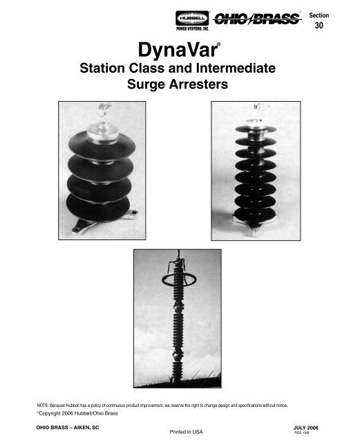
DynaVar<br />
®<br />
Station Class and Intermediate<br />
Surge Arresters<br />
NOTE: Because Hubbell has a policy of continuous product improvement, we reserve the right to change design and specifications without notice.<br />
©<br />
Copyright 2006 Hubbell/Ohio Brass<br />
OHIO BRASS – AIKEN, SC<br />
Printed in USA<br />
JULY 2006<br />
RGS 10M
30-<br />
JULY 2006<br />
POWER SYSTEMS, INC.<br />
Introduction<br />
® ®<br />
With the introduction of the station class Type <strong>PVN</strong>,<br />
Ohio Brass has expanded its line of polymer-housed<br />
arresters for distribution, substation and transmission<br />
applications. <strong>PVN</strong> arresters are suitable for applications<br />
up through 230 kV. The <strong>PVI</strong> arresters are suitable for<br />
applications up through 138 kV.<br />
These designs combine the advantages of a polymer<br />
housing and metal-oxide varistor valve blocks, and offer<br />
the benefits of a one piece arrester construction for<br />
all voltage ratings. Stacking of individual arrester units<br />
is not required with polymer housings.<br />
Also available are porcelain and silicone station (Type<br />
VN, SVN and VL) arresters.<br />
All DynaVar Intermediate and Station Class Surge<br />
Arresters in this catalog comply with ANSI/IEEE<br />
Standard C62.11-1999. In addition, they are tested<br />
to IEC 99-4.<br />
The Type <strong>PVN</strong> Station Class Arresters described in this<br />
publication are protected by patent numbers 4,656,555;<br />
4,899,248; 4,905,118; 5,043,838; 5,138,517; 5,159,159<br />
and others pending.<br />
The Type <strong>PVI</strong> Intermediate Class Arresters described<br />
in this publication are protected by patent numbers<br />
4,656,555; 4,899,248; 4,905,118 and others pending.<br />
Warranty - Material<br />
Hubbell Power Systems, Inc. warrants all products sold by it to be merchantable (as such<br />
term is defined in the Uniform Commercial Code) and to be free from defects in material and<br />
workmanship. Buyer must notify the Company promptly of any claim under this warranty. The<br />
Buyer's exclusive remedy for breach of this warranty shall be the repair or replacement, F.O.B.<br />
factory, at the Company's option, of any product defective under the warranty which is returned<br />
to the Company within one year from the date of shipment. NO OTHER WARRANTY, WHETHER<br />
EXPRESS OR ARISING BY OPERATION OF LAW, COURSE OF DEALING, USAGE OF<br />
TRADE OR OTHERWISE IMPLIED, SHALL EXIST IN CONNECTION WITH THE COMPANY'S<br />
PRODUCTS OR ANY SALE OR USE THEREOF. The Company shall in no event be liable for<br />
any loss of profits or any consequential or special damages incurred by Buyer. The Company's<br />
warranty shall run only to the first Buyer of a product from the Company, from the Company's<br />
distributor, or from an original equipment manufacturer reselling the Company's product, and is<br />
non-assignable and non-transferable and shall be of no force and effect if asserted by any person<br />
other than such first Buyer. This warranty applies only to the use of the product as intended<br />
by Seller and does not cover any misapplication or misuse of said product.<br />
Warranty - Application<br />
Hubbell Power Systems, Inc. does not warrant the accuracy of and results from product or<br />
system performance recommendations resulting from any engineering analysis or study. This<br />
applies regardless of whether a charge is made for the recommendation, or if it is provided free<br />
of charge.<br />
Responsibility for selection of the proper product or application rests solely with the purchaser. In<br />
the event of errors or inaccuracies determined to be caused by Hubbell Power Systems, Inc., its<br />
liability will be limited to the re-performance of any such analysis or study.<br />
Table of Contents<br />
Page<br />
Introduction.................................................................2<br />
Warranty......................................................................2<br />
General Arrester Information.......................................3<br />
Arrester Application.................................................3<br />
Pressure Relief........................................................3<br />
Temporary Overvoltage Capability..........................3<br />
Polymer Housed Arresters..........................................4<br />
Description..............................................................4<br />
ESP Weathershed Material.....................................4<br />
Construction............................................................4<br />
Benefits...................................................................4<br />
Seismic Performance..............................................4<br />
Key to the Catalog Numbers.......................................5<br />
<strong>PVI</strong> Polymer Housed Intermediate Arrester................6<br />
Protective Characteristics........................................6<br />
Dimensions and Mounting.......................................7<br />
<strong>PVI</strong> Nameplates......................................................7<br />
<strong>PVI</strong> Terminals..........................................................8<br />
Mounting Information...............................................8<br />
<strong>PVI</strong>-LP Polymer Housed Intermediate Class<br />
Arresters.....................................................................9<br />
Dimensions and Mounting.......................................9<br />
Protective Characteristics......................................10<br />
<strong>PVI</strong>A Intermediate Class Surge Arresters.................11<br />
Dimensions and Mounting.....................................11<br />
Protective Characteristics......................................12<br />
<strong>PVN</strong> Polymer Housed Station Arresters...................13<br />
Protective Characteristics......................................13<br />
Mounting Positions................................................13<br />
Dimensions and Mounting.....................................14<br />
Grading Rings.......................................................14<br />
<strong>PVN</strong> Terminals.......................................................14<br />
Packaging (<strong>PVI</strong>/<strong>PVN</strong>)............................................15<br />
<strong>PVN</strong> Nameplates...................................................15<br />
Base Mounting Information...................................15<br />
Crossarm Mounting...............................................15<br />
Discharge Counters (<strong>PVI</strong>/<strong>PVN</strong>).............................15<br />
Insulating Subbases (<strong>PVI</strong>/<strong>PVN</strong>)............................15<br />
Brackets................................................................16<br />
<strong>PVN</strong>A Polymer Housed Station Class<br />
Surge Arresters.........................................................17<br />
Dimensions and Mounting.....................................17<br />
Protective Characteristics......................................18<br />
VL and VN Porcelain Housed Station Class<br />
Arresters...................................................................19<br />
Introduction............................................................19<br />
Application Guide..................................................19<br />
Description and Operation.....................................19<br />
Protective Characteristics......................................20<br />
Nameplates...........................................................20<br />
Dimensions and Mounting.....................................21<br />
SVN Polymer Housed Arresters................................22<br />
Construction..........................................................22<br />
Catalog Ordering System......................................23<br />
Protective Characteristics......................................25<br />
Nameplates...........................................................25<br />
Dimensions and Mounting.....................................26<br />
Discharge Counters..................................................27<br />
Insulating Subbases..............................................27<br />
Arrester Routine & Design Testing.........................28<br />
OHIO BRASS – AIKEN, SC
POWER SYSTEMS, INC.<br />
® ®<br />
30-<br />
General Arrester Information<br />
NORMALLY RECOMMENDED STATION DYNAVAR<br />
MCOV FOR VARIOUS SYSTEM VOLTAGES<br />
Nominal<br />
2.40<br />
4.16<br />
4.8<br />
6.9<br />
8.32<br />
12<br />
12.47<br />
13.2<br />
13.8<br />
20.78<br />
22.86<br />
23<br />
24.94<br />
34.5<br />
46<br />
69<br />
115<br />
138<br />
161<br />
230<br />
345<br />
400<br />
System<br />
L-L Voltage<br />
kV<br />
Maximum<br />
2.52<br />
4.37<br />
5.04<br />
7.25<br />
8.74<br />
12.6<br />
13.1<br />
13.9<br />
14.5<br />
21.8<br />
24<br />
24.2<br />
26.2<br />
36.2<br />
48.3<br />
72.5<br />
121<br />
145<br />
169<br />
242<br />
362<br />
420<br />
Arrester Application<br />
Arrester MCOV (kV)<br />
Temporarily Ungrounded,<br />
Impedance Grounded or<br />
Grounded<br />
Ungrounded Circuits<br />
Neutral<br />
Circuits (1)<br />
(2)<br />
2.55<br />
2.55<br />
5.1<br />
5.1<br />
5.1<br />
7.65<br />
7.65<br />
8.4<br />
8.4<br />
12.7<br />
15.3<br />
15.3<br />
15.3<br />
22<br />
29<br />
42<br />
70<br />
84<br />
98<br />
140<br />
209<br />
245<br />
2.55<br />
5.1<br />
5.1<br />
7.65<br />
7.65<br />
10.2<br />
12.7<br />
12.7<br />
12.7<br />
19.5<br />
19.5<br />
19.5<br />
22<br />
29<br />
39<br />
57<br />
98<br />
115<br />
140<br />
209<br />
—<br />
—<br />
2.55<br />
5.1<br />
5.1<br />
7.65<br />
8.4<br />
12.7<br />
12.7<br />
12.7<br />
15.3<br />
22<br />
22<br />
22<br />
24<br />
36<br />
48<br />
70<br />
115<br />
131<br />
152<br />
220<br />
—<br />
—<br />
(1) For normal duty. Line-to-ground fault up to 30 minutes.<br />
(2) For severe duty. Line-to-ground fault up to 2,000 hours.<br />
The DynaVar arrester is described by its maximum continuous<br />
line-to-ground operating voltage (MCOV). The arrester’s<br />
most important application criterion is the maximum voltage<br />
which can be continuously applied.<br />
For effectively grounded neutral systems, any DynaVar arrester<br />
with MCOV equal to maximum line-to-neutral kV is the<br />
normal application. For example, a 138 kV system usually<br />
has a maximum line-to-line continuous voltage of 145 kV rms.<br />
145 kV divided by √ 3 gives 84 kV line-to-ground voltage. The<br />
appropriate DynaVar arrester for this application is the Dyna-<br />
Var 84, with MCOV of 84 kV.<br />
For ungrounded or impedance grounded systems, the gapless<br />
DynaVar arrester’s temporary overvoltage capability is<br />
used. For applications where a ground fault is expected to be<br />
removed within 30 minutes, the minimum MCOV is maximum<br />
system line-to-line voltage divided by 1.25. For extended<br />
operation under ground fault conditions up to 2,000 hours but<br />
not to exceed five percent of service life, the minimum MCOV<br />
is maximum system line-to-line voltage divided by 1.11.<br />
DynaVar arresters are designed to be used where average<br />
ambient temperature does not exceed 40°C (104°F) and the<br />
daily maximum temperature does not exceed 60°C (140°F).<br />
Pressure Relief<br />
Arrester<br />
Type<br />
VLA*<br />
VL*<br />
VN*<br />
SVN*<br />
<strong>PVN</strong>**<br />
<strong>PVN</strong>A**<br />
<strong>PVI</strong>**<br />
<strong>PVI</strong>-LP**<br />
<strong>PVI</strong>A**<br />
* Rating for initial venting only.<br />
** Polymer arresters will survive multiple venting operations.<br />
Energy Capability<br />
Kilojoules per kV of MCOV<br />
Type<br />
<strong>PVN</strong>A, <strong>PVI</strong>, <strong>PVI</strong>-LP<br />
<strong>PVI</strong>A<br />
<strong>PVN</strong><br />
VL/VLA<br />
VN<br />
SVN<br />
Pressure Relief Capability-Symmetrical rms kA<br />
ANSI Standard<br />
Ohio Brass<br />
C62.11 Minimum Demonstrated Values<br />
None<br />
10<br />
40-65<br />
65<br />
40-65<br />
93<br />
40-65<br />
63<br />
40-65<br />
80<br />
40-65<br />
40<br />
16.1<br />
60<br />
16.1<br />
16.1<br />
16.1<br />
16.1<br />
All DynaVar station-intermediate arresters exceed pressure<br />
relief requirements of ANSI C62.11.<br />
(1) For currents .65kA or less<br />
(2) For currents 1.00kA or less<br />
(3) For currents 1.5 kA or less<br />
(4) For currents .4 or less<br />
Max. Energy Discharge<br />
Capability kJ/kV - MCOV<br />
5.1 (1)<br />
3.6 (4)<br />
7.3 (2)<br />
7.3 (2)<br />
11.5 (3)<br />
11.5 (3)<br />
Switching surge capability of DynaVar arresters is expressed<br />
in terms of dissipated energy.<br />
These capabilities assume a two shot energy discharge takes<br />
place within one minute.<br />
The indicated current levels are not an arrester limitation, but<br />
are related to the indicated energy capability.<br />
Calculations based on the conservative assumption that the<br />
entire line length is charged to maximum surge voltage are<br />
easily made, and the values obtained seldom exceed the<br />
considerable energy capability of the DynaVar arrester.<br />
Temporary Overvoltage Capability<br />
DynaVar arresters are gapless and consist of a column of metaloxide<br />
blocks connected between line and ground. The blocks<br />
can withstand a significant power frequency overvoltage for a<br />
limited time, depending on the magnitude of any immediately<br />
preceding surge duty. This duty can be the result of switching<br />
surges on higher voltage lines, or from other sources. The energy<br />
discharge capability is found in the above table.<br />
All of the TOV curves are available in the Design Test Reports<br />
which are listed on page 30-29. The Design Test Reports are<br />
available on our web site www.hubbellpowersystems. com or<br />
by calling an Ohio Brass representative. The temporary overvoltage<br />
capability can be determined from this curve. The prior<br />
duty curve of this table is based upon absorption of rated energy<br />
immediately preceding application of the overvoltage.<br />
OHIO BRASS – AIKEN, SC<br />
JULY 2006
30-<br />
POWER SYSTEMS, INC.<br />
® ®<br />
Polymer Housed Arresters (Type <strong>PVI</strong> and <strong>PVN</strong>)<br />
Description<br />
The Type <strong>PVI</strong> & <strong>PVN</strong> arresters contain the same high-quality<br />
metal-oxide varistors used in other Ohio Brass DynaVar<br />
arresters which have operated successfully since 1981.<br />
They have all the MOV advantages such as high temporary<br />
overvoltage capability, contamination resistance, improved<br />
surge-duty capability and excellent protective characteristics.<br />
In the unlikely event of arrester failure, violent fragmentation<br />
of porcelain is eliminated. Instead, the higher available<br />
fault currents may cause splits or tears in the polymer rubber<br />
housing while the internal fiberglass wrap restrains the valve<br />
elements.<br />
Weight is greatly reduced compared to conventional porcelain-housed<br />
designs. Installation is simplified because with<br />
the reduced weight, a patented, single housing design can be<br />
utilized for all arrester voltage ratings.<br />
The small diameter line end terminal hardware permits closer<br />
phase-to-phase and phase-to-ground spacings useful in modern<br />
compact substation designs and on mobile transformer<br />
applications.<br />
ESP Weathershed Material<br />
The arrester housing is made of ESP silicone alloy weathershed<br />
material that has been successful in field operations for<br />
over a decade. The improved ESP housing resists tracking<br />
from surface leakage currents and the housing contour<br />
provides exceptional leakage distance. The housing sections<br />
are mechanically secured to provide a housing suitable for<br />
high pressure hot-washing in locations where contamination<br />
is severe and routine station maintenance includes washing<br />
procedures. Contact Ohio Brass for recommended procedures.<br />
Construction<br />
The housing consists of one or more molded sections which<br />
are mechanically secured into one continuous length for all<br />
arrester voltage ratings. The base of the arrester is equipped<br />
with a factory installed casting which provides the conventional<br />
8.75 inch diameter bolt circle customarily provided with<br />
intermediate and the 10 inch diameter bolt circle for station<br />
class surge arresters.<br />
The varistor column is centered and restrained in alignment<br />
with tightly woven fiberglass filament strands impregnated<br />
with epoxy resin. The interstices between the stranding are<br />
filled with a silicone <strong>dielec</strong>tric compound so the design is free<br />
of air and moisture. The fiberglass stranding construction provides<br />
fault withstand capability in excess of the requirements<br />
of IEEE/ANSI C62.11-1999.<br />
Benefits<br />
The <strong>PVI</strong> and <strong>PVN</strong> arresters have many additional benefits<br />
that are included with the polymer housing.<br />
• A <strong>PVI</strong> or <strong>PVN</strong> arrester unit are less than half the weight<br />
of an equivalent porcelain-housed arrester. This makes<br />
transportation, handling and installation much easier.<br />
• All voltage ratings are of single unit design. Field assembly<br />
of stacked units is not required.<br />
• With a reduced diameter of energized line terminal and<br />
grading rings, the <strong>PVI</strong> and <strong>PVN</strong> arresters reduce space<br />
requirements.<br />
• The polymer housing makes the <strong>PVI</strong> and <strong>PVN</strong> arresters<br />
much safer than porcelain arresters.<br />
• Single-unit, high voltage design provides improved contamination<br />
performance over multi-unit designs.<br />
• Closer spacing — Smaller line end casting and smaller<br />
grading rings allow closer phase-to-phase spacing.<br />
• Increased creepage — Standard units may fulfill high<br />
creep requirements.<br />
• Minimal Internal Atmosphere — Will not “breathe” or leak,<br />
eliminates moisture ingress, a cause of arrester failure.<br />
SEISMIC PERFORMANCE: All <strong>PVI</strong> up to 84kV MCOV, and<br />
all <strong>PVN</strong> up to 115 kV MCOV meet IEEE 693 as of 1997 High<br />
Performance Level. 3.2 g Time History.<br />
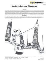
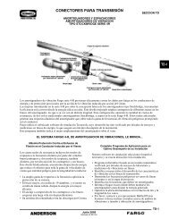
Top Cap<br />
Fiberglass Wrap<br />
Coated with Silicone<br />
Dielectric Compound<br />
ESP Housing<br />
MOV Element<br />
Contact Disc<br />
Ground<br />
End<br />
Casting<br />
Section View of Typical <strong>PVI</strong>/<strong>PVN</strong> Arrester<br />
JULY 2006<br />
OHIO BRASS – AIKEN, SC
POWER SYSTEMS, INC.<br />
® ®<br />
30-<br />
Key to the Catalog Numbers<br />
Polymer<br />
Housed<br />
“0” ... Type <strong>PVI</strong><br />
“1” ... Type <strong>PVN</strong><br />
3 1 X X X<br />
X<br />
Standard<br />
Arrester<br />
Catalog<br />
Number<br />
003<br />
005<br />
008<br />
009<br />
010<br />
013<br />
015<br />
Maximum<br />
Continuous<br />
Operating<br />
Voltage MCOV<br />
kV rms<br />
2.55<br />
5.10<br />
7.65<br />
8.40<br />
10.20<br />
12.70<br />
15.30<br />
017<br />
019<br />
022<br />
024<br />
029<br />
031<br />
036<br />
17.00<br />
19.50<br />
22.00<br />
24.40<br />
29.00<br />
31.50<br />
36.50<br />
“0” ... Small Top, Tripod Base<br />
“1” ... Small Top, Small Base<br />
(vertical mounting only)<br />
039<br />
042<br />
048<br />
057<br />
070<br />
076<br />
084<br />
088<br />
098<br />
106<br />
115<br />
39.00<br />
42.00<br />
48.00<br />
57.00<br />
70.00<br />
76.00<br />
84.00<br />
88.00*<br />
98.00*<br />
106.00*<br />
115.00*<br />
*Available in <strong>PVN</strong> only.<br />
“2” ... Tripod Top, Small Base<br />
(underhung)<br />
“3” ... Tripod Top, Tripod Base<br />
“4” ... Spade Top,<br />
Tripod Base<br />
(only available<br />
with Type <strong>PVN</strong>)<br />
“5” ... Tripod Top,<br />
Spade Base<br />
(underhung)<br />
only available<br />
with Type <strong>PVN</strong><br />
OHIO BRASS – AIKEN, SC<br />
JULY 2006
30-<br />
POWER SYSTEMS, INC.<br />
® ®<br />
Type <strong>PVI</strong> Polymer Housed Intermediate Class Arrester<br />
Protective Characteristics<br />
Type<br />
<strong>PVI</strong><br />
<strong>PVI</strong><br />
<strong>PVI</strong><br />
<strong>PVI</strong><br />
<strong>PVI</strong><br />
<strong>PVI</strong><br />
<strong>PVI</strong><br />
<strong>PVI</strong><br />
<strong>PVI</strong><br />
<strong>PVI</strong><br />
<strong>PVI</strong><br />
<strong>PVI</strong><br />
<strong>PVI</strong><br />
<strong>PVI</strong><br />
<strong>PVI</strong><br />
<strong>PVI</strong><br />
<strong>PVI</strong><br />
<strong>PVI</strong><br />
<strong>PVI</strong><br />
<strong>PVI</strong><br />
<strong>PVI</strong><br />
<strong>PVI</strong><br />
<strong>PVI</strong><br />
<strong>PVI</strong><br />
<strong>PVI</strong><br />
Standard<br />
Arrester<br />
Catalog<br />
Number<br />
300003<br />
300005<br />
300008<br />
300009<br />
300010<br />
300013<br />
300015<br />
300017<br />
300019<br />
300022<br />
300024<br />
300029<br />
300031<br />
300036<br />
300039<br />
300042<br />
300048<br />
300057<br />
300070<br />
300076<br />
300084<br />
300088<br />
300098<br />
300106<br />
300115<br />
Arrester Ratings<br />
Duty<br />
Cycle<br />
Rating<br />
kV rms<br />
3<br />
6<br />
9<br />
10<br />
12<br />
15<br />
18<br />
21<br />
24<br />
27<br />
30<br />
36<br />
39<br />
45<br />
48<br />
54<br />
60<br />
72<br />
90<br />
96<br />
108<br />
108<br />
120<br />
132<br />
144<br />
Maximum<br />
Continuous<br />
Operating<br />
Voltage<br />
kV rms<br />
2.55<br />
5.1<br />
7.65<br />
8.4<br />
10.2<br />
12.7<br />
15.3<br />
17<br />
19.5<br />
22<br />
24.4<br />
29<br />
31.5<br />
36.5<br />
39<br />
42<br />
48<br />
57<br />
70<br />
76<br />
84<br />
88<br />
98<br />
106<br />
115<br />
Maximum<br />
0.5µs<br />
Discharge<br />
Voltage<br />
kV (1)<br />
8.6<br />
17.1<br />
25.8<br />
28.4<br />
34.1<br />
42.9<br />
51.6<br />
56.9<br />
68.3<br />
77.4<br />
85.3<br />
100.0<br />
108.4<br />
125.1<br />
130.9<br />
148.0<br />
170.6<br />
199.0<br />
250.0<br />
261.7<br />
296.0<br />
296.0<br />
327.7<br />
375.2<br />
392.0<br />
Maximum<br />
Switching<br />
Surge<br />
Protective<br />
Level<br />
kV (2)<br />
6.4<br />
12.7<br />
19.1<br />
21.1<br />
25.3<br />
31.8<br />
38.3<br />
42.2<br />
50.6<br />
57.4<br />
63.3<br />
73.9<br />
80.4<br />
92.8<br />
97.1<br />
109.8<br />
126.5<br />
147.7<br />
185.7<br />
194.1<br />
219.5<br />
219.5<br />
243.0<br />
278.3<br />
290.9<br />
1.5kA<br />
6.8<br />
13.6<br />
20.5<br />
22.6<br />
27.1<br />
34.1<br />
40.9<br />
45.1<br />
54.2<br />
61.4<br />
67.7<br />
79.0<br />
86.1<br />
99.3<br />
103.9<br />
117.5<br />
135.4<br />
158.1<br />
198.7<br />
207.7<br />
234.9<br />
234.9<br />
260.1<br />
297.8<br />
311.3<br />
3kA<br />
7.2<br />
14.4<br />
21.6<br />
23.8<br />
28.6<br />
36.0<br />
43.2<br />
47.7<br />
57.2<br />
64.9<br />
71.5<br />
83.5<br />
90.9<br />
104.9<br />
109.7<br />
124.0<br />
143.0<br />
166.9<br />
209.8<br />
219.4<br />
248.1<br />
248.1<br />
274.7<br />
314.5<br />
328.7<br />
Maximum Discharge Voltage<br />
Using an 8/20<br />
Current Wave-kV<br />
5kA<br />
7.5<br />
15.0<br />
22.6<br />
24.9<br />
29.9<br />
37.6<br />
45.2<br />
49.9<br />
59.9<br />
67.9<br />
74.8<br />
87.3<br />
95.1<br />
109.8<br />
114.8<br />
129.8<br />
149.6<br />
174.6<br />
219.5<br />
229.5<br />
259.6<br />
259.6<br />
287.4<br />
329.1<br />
343.9<br />
10kA<br />
8.1<br />
16.2<br />
24.4<br />
26.9<br />
32.3<br />
40.6<br />
48.8<br />
53.8<br />
64.6<br />
73.2<br />
80.7<br />
94.2<br />
102.6<br />
118.4<br />
123.8<br />
140.0<br />
161.4<br />
188.4<br />
236.8<br />
247.6<br />
280.0<br />
280.0<br />
310.0<br />
355.0<br />
371.0<br />
20kA<br />
9.0<br />
17.9<br />
27.0<br />
29.8<br />
35.8<br />
44.9<br />
54.0<br />
59.6<br />
71.5<br />
81.0<br />
89.3<br />
104.0<br />
113.6<br />
131.1<br />
137.0<br />
155.0<br />
178.7<br />
209.0<br />
262.0<br />
274.1<br />
310.0<br />
310.0<br />
343.2<br />
393.0<br />
411.0<br />
40kA<br />
10.1<br />
20.2<br />
30.4<br />
33.5<br />
40.3<br />
50.6<br />
60.9<br />
67.1<br />
80.6<br />
91.3<br />
101.0<br />
117.0<br />
127.9<br />
147.6<br />
154.4<br />
174.6<br />
201.0<br />
235.0<br />
295.0<br />
308.8<br />
349.2<br />
349.2<br />
386.6<br />
443.0<br />
463.0<br />
(1) Maximum discharge voltage for a 10-kA impulse current wave which produces a voltage wave cresting in 0.5 µs. This can be used for<br />
coordination where front-of-wave sparkover was formerly used.<br />
(2) Based on a 500A surge of 45-µs time to crest.<br />
JULY 2006<br />
OHIO BRASS – AIKEN, SC
POWER SYSTEMS, INC.<br />
® ®<br />
30-<br />
Type <strong>PVI</strong> Polymer Housed Intermediate Class Arrester<br />
Dimensions and Mounting<br />
Type<br />
<strong>PVI</strong><br />
<strong>PVI</strong><br />
<strong>PVI</strong><br />
<strong>PVI</strong><br />
<strong>PVI</strong><br />
<strong>PVI</strong><br />
<strong>PVI</strong><br />
<strong>PVI</strong><br />
<strong>PVI</strong><br />
<strong>PVI</strong><br />
<strong>PVI</strong><br />
<strong>PVI</strong><br />
<strong>PVI</strong><br />
<strong>PVI</strong><br />
<strong>PVI</strong><br />
<strong>PVI</strong><br />
<strong>PVI</strong><br />
<strong>PVI</strong><br />
<strong>PVI</strong><br />
<strong>PVI</strong><br />
<strong>PVI</strong><br />
<strong>PVI</strong><br />
<strong>PVI</strong><br />
<strong>PVI</strong><br />
<strong>PVI</strong><br />
Standard<br />
Arrester<br />
Catalog<br />
Number<br />
300003<br />
300005<br />
300008<br />
300009<br />
300010<br />
300013<br />
300015<br />
300017<br />
300019<br />
300022<br />
300024<br />
300029<br />
300031<br />
300036<br />
300039<br />
300042<br />
300048<br />
300057<br />
300070<br />
300076<br />
300084<br />
300088<br />
300098<br />
300106<br />
300115<br />
Arrester Ratings<br />
Maximum<br />
Duty Continuous<br />
Cycle Operating<br />
Rating Voltage<br />
kV rms kV rms<br />
3<br />
6<br />
9<br />
10<br />
12<br />
15<br />
18<br />
21<br />
24<br />
27<br />
30<br />
36<br />
39<br />
45<br />
48<br />
54<br />
60<br />
72<br />
90<br />
96<br />
108<br />
108<br />
120<br />
132<br />
144<br />
2.55<br />
5.1<br />
7.65<br />
8.4<br />
10.2<br />
12.7<br />
15.3<br />
17<br />
19.5<br />
22<br />
24.4<br />
29<br />
31.5<br />
36.5<br />
39<br />
42<br />
48<br />
57<br />
70<br />
76<br />
84<br />
88<br />
98<br />
106<br />
115<br />
Figure<br />
Number<br />
1<br />
1<br />
1<br />
1<br />
1<br />
1<br />
1<br />
1<br />
1<br />
1<br />
1<br />
1<br />
1<br />
1<br />
1<br />
1<br />
1<br />
1<br />
2<br />
2<br />
2<br />
2<br />
2<br />
2<br />
2<br />
“X”<br />
Dimension<br />
(Inches)<br />
9.5<br />
9.5<br />
9.5<br />
9.5<br />
9.5<br />
12.0<br />
12.0<br />
12.0<br />
17.5<br />
17.5<br />
17.5<br />
17.5<br />
22.8<br />
22.8<br />
22.8<br />
22.8<br />
33.2<br />
33.2<br />
44.0<br />
44.0<br />
44.0<br />
44.0<br />
66.5<br />
66.5<br />
66.5<br />
Leakage<br />
Distance<br />
(Inches)<br />
19<br />
19<br />
19<br />
19<br />
19<br />
26<br />
26<br />
26<br />
40<br />
40<br />
40<br />
40<br />
54<br />
54<br />
54<br />
54<br />
81<br />
81<br />
109<br />
109<br />
109<br />
109<br />
162<br />
162<br />
162<br />
Minimum Mounting<br />
Spacing on center†<br />
Phase to<br />
Phase<br />
(in-line)<br />
(Inches)<br />
9.5<br />
9.5<br />
9.5<br />
9.5<br />
9.5<br />
9.5<br />
9.5<br />
9.5<br />
9.5<br />
10.5<br />
10.5<br />
12.5<br />
13.5<br />
15.5<br />
16.5<br />
18.5<br />
20.5<br />
23.5<br />
40.0<br />
42.0<br />
46.0<br />
46.0<br />
51.0<br />
55.0<br />
58.0<br />
Phase to<br />
Ground<br />
(Inches)<br />
5.5<br />
5.5<br />
5.5<br />
5.5<br />
5.5<br />
5.5<br />
5.8<br />
6.8<br />
7.8<br />
8.8<br />
8.8<br />
10.8<br />
11.8<br />
13.8<br />
14.8<br />
16.8<br />
18.8<br />
21.8<br />
33.0<br />
35.0<br />
39.0<br />
39.0<br />
44.0<br />
47.0<br />
50.0<br />
Net<br />
Weight<br />
(Pounds)<br />
11<br />
12<br />
12<br />
12<br />
12<br />
15<br />
15<br />
15<br />
20<br />
20<br />
21<br />
21<br />
26<br />
27<br />
27<br />
28<br />
38<br />
39<br />
52<br />
53<br />
54<br />
54<br />
67.5<br />
67.5<br />
67.5<br />
FIGURE 1<br />
For standard terminals shown in Figure 1 and 2 (page 30-8) and standard package, order suffix<br />
code 3001. For non-standard requirements contact your Ohio Brass representative.<br />
<strong>PVI</strong> Namplates<br />
Each arrester is identified with a nameplate attached to the<br />
line end casting.<br />
These nameplates display the maximum continuous operating<br />
voltage rating, the duty cycle voltage rating, the pressure<br />
relief current rating, the catalog number and the year of the<br />
manufacture.<br />
FIGURE 2<br />
Grading Rings<br />
Rings are required on arresters 70 kV<br />
MCOV and above.<br />
kV - MCOV<br />
70 - 88<br />
98 - 115<br />
Diameter<br />
(Inches) (B)<br />
14<br />
16.5<br />
Drop<br />
(Inches) (A)<br />
4.8<br />
9<br />
† Minimum clearances are based<br />
on arrester protective levels<br />
and should be increased when<br />
necessary to meet local requirements<br />
for spacing of energized<br />
equipment.<br />
OHIO BRASS – AIKEN, SC<br />
JULY 2006
30-<br />
® ®<br />
POWER SYSTEMS, INC.<br />
<strong>PVI</strong> Terminals<br />
Standard line and ground terminals will accommodate conductor sizes from 1/4 inch to 13/16<br />
inch diameter (.25 - .81 inch diameter). The terminals are of hot-dip galvanized malleable<br />
iron, compatible with either aluminum or copper.<br />
Standard Line terminal Number 71874 Standard Ground terminal Number 71874.<br />
Terminal Number 273373 is not regularly<br />
furnished, but is available on order.<br />
NOTE: Use suffix code 3002 to order,<br />
i.e., 3000033002.<br />
Base Mounting Information<br />
The end casting is furnished with three<br />
holes 120° on 8.75 inch diameter bolt<br />
circle. These mounting holes are 0.56<br />
inch diameter to accommodate 1/2 inch<br />
bolts. (Mounting bolts and washers are<br />
not provided with the arrester.)<br />
Mounting Positions<br />
Type <strong>PVI</strong> arresters may be mounted vertically, horizontally or<br />
underhung, provided the cantilever moment is not excessive.<br />
(<strong>PVI</strong> 98, 106, 115kV MCOV arresters are designed for vertical<br />
mounting only.) Underhung mounting requires factory assembly<br />
of the base mounting hardware at the top of the arrester.<br />
Use catalog number series 3020XX3001.<br />
The rated (ultimate) cantilever moments of Type <strong>PVI</strong> arrester<br />
with the tripod base is 10,000 in-lbs and the maximum working<br />
moment is 5,000 in-lbs. For the small base, the maximum<br />
working moment is 3,000 in-lbs.<br />
For horizontal mounting, the residual cantilever loads are<br />
given below. They already take into account the reasonable<br />
worst case loading consisting of 120 m.p.h. wind and the<br />
weight of the arrester and represent the maximum residual<br />
load that can be applied to the horizontal arrester without<br />
exceeding its maximum cantilever working load.<br />
Residual Cantilever Load-Lbs.<br />
Horizontal Mounting <strong>PVI</strong><br />
kV - MCOV<br />
2.55 - 10.2<br />
12.7 - 17.0<br />
19.5 - 29.0<br />
31.5 - 42.0<br />
48.0 - 57.0<br />
70.0 - 84.0<br />
Cat. No. 300XXX<br />
Cat. No. 302XXX<br />
467<br />
317<br />
274<br />
203<br />
127<br />
74<br />
Connector Number 271414 used with<br />
all terminal combinations. Range of<br />
conductor sizes .25 to .81 inch.<br />
Bolt<br />
Circle<br />
(Inches)<br />
8.75<br />
Bolt<br />
Size<br />
(Inches)<br />
0.5<br />
Attachment Lug<br />
Thickness<br />
(Inches)<br />
0.75<br />
Hole Size<br />
(Inches)<br />
0.56<br />
Crossarm Mounting<br />
Type <strong>PVI</strong> arresters can be<br />
easily mounted on a NEMA<br />
crossarm bracket, by using<br />
catalog #3010XX3011 (available<br />
through 42 kV MCOV).<br />
JULY 2006<br />
OHIO BRASS – AIKEN, SC
POWER SYSTEMS, INC.<br />
<strong>PVI</strong>-LP ®<br />
Polymer Housed<br />
Intermediate Class Arrester<br />
® ®<br />
30-<br />
.56 DIA - 4 HOLES<br />
1.75<br />
2.19<br />
3.6<br />
1.75<br />
Clamp Type Line<br />
& Ground Terminals<br />
Suitable for use with<br />
CU or AL Conductor<br />
.25 to .81 Dia.<br />
Clamp Type Line<br />
& Ground Terminals<br />
Suitable for use with<br />
CU or AL Conductor<br />
.25 to .81 Dia.<br />
[X]<br />
4.3 DIA<br />
[X]<br />
4.3 DIA<br />
.75<br />
NAMEPLATE<br />
.75<br />
NAMEPLATE<br />
Figure 1 <strong>PVI</strong>-LP with Eye-bolt Line Terminal Figure 2 <strong>PVI</strong>-LP with four-hole NEMA Pad Line Terminal<br />
<strong>PVI</strong>-LP Terminals:<br />
Standard line and ground terminal and standard domestic packaging: use code3001 (Example: 3008XX3001, Figure 1)<br />
Four hole NEMA line terminal, standard ground terminal and domestic packaging: use code 3002 (Example: 3008XX3002, Figure 2))<br />
Other options: For underhung mounting: use catalog number 3028XX3001 or 3028XX3002.<br />
Dimensions and Mounting<br />
Type<br />
<strong>PVI</strong>-LP<br />
<strong>PVI</strong>-LP<br />
<strong>PVI</strong>-LP<br />
<strong>PVI</strong>-LP<br />
<strong>PVI</strong>-LP<br />
<strong>PVI</strong>-LP<br />
<strong>PVI</strong>-LP<br />
<strong>PVI</strong>-LP<br />
<strong>PVI</strong>-LP<br />
<strong>PVI</strong>-LP<br />
<strong>PVI</strong>-LP<br />
<strong>PVI</strong>-LP<br />
<strong>PVI</strong>-LP<br />
<strong>PVI</strong>-LP<br />
<strong>PVI</strong>-LP<br />
<strong>PVI</strong>-LP<br />
<strong>PVI</strong>-LP<br />
<strong>PVI</strong>-LP<br />
Standardster<br />
Catalog<br />
Number<br />
300803<br />
300805<br />
300808<br />
300809<br />
300610<br />
300813<br />
300815<br />
300817<br />
300620<br />
300822<br />
300824<br />
300629<br />
300831<br />
300636<br />
300639<br />
300642<br />
300648<br />
300657<br />
MCOV<br />
2.55<br />
5.1<br />
7.65<br />
8.4<br />
10.2<br />
12.7<br />
15.3<br />
17.0<br />
19.5<br />
22.0<br />
24.4<br />
29.0<br />
31.5<br />
36.5<br />
39.0<br />
42.0<br />
48.0<br />
57.0<br />
“X”<br />
Dimension<br />
(inches)<br />
6.8<br />
6.8<br />
6.8<br />
6.8<br />
6.8<br />
12.2<br />
12.2<br />
12.2<br />
12.2<br />
17.6<br />
17.6<br />
17.6<br />
23.0<br />
23.0<br />
23.0<br />
28.4<br />
28.4<br />
33.8<br />
Leakage<br />
Distance<br />
(inches)<br />
15.4<br />
15.4<br />
15.4<br />
15.4<br />
15.4<br />
30.8<br />
30.8<br />
30.8<br />
30.8<br />
46.2<br />
46.2<br />
46.2<br />
61.6<br />
61.6<br />
61.6<br />
77.0<br />
77.0<br />
92.4<br />
Minimum Mounting<br />
Spacing on Center<br />
(inches)<br />
Ph-Ph<br />
4.4<br />
4.6<br />
4.7<br />
4.9<br />
4.9<br />
6.2<br />
6.6<br />
7.6<br />
7.6<br />
9.6<br />
9.8<br />
9.8<br />
12.8<br />
12.8<br />
12.8<br />
15.8<br />
15.8<br />
19.8<br />
Ph-Grd<br />
3.3<br />
3.2<br />
3.3<br />
3.5<br />
3.5<br />
4.8<br />
5.2<br />
6.2<br />
6.2<br />
8.2<br />
8.4<br />
8.4<br />
11.4<br />
11.4<br />
11.4<br />
14.4<br />
14.4<br />
18.4<br />
Net<br />
Weight<br />
(pounds)<br />
6.2<br />
6.2<br />
6.2<br />
6.2<br />
6.2<br />
10.0<br />
10.0<br />
10;0<br />
10;0<br />
13.5<br />
13.5<br />
13.5<br />
17;0<br />
17;0<br />
17;0<br />
19.6<br />
19.6<br />
23.1<br />
OHIO BRASS – AIKEN, SC<br />
JULY 2006
30-10<br />
POWER SYSTEMS, INC.<br />
® ®<br />
Base Mounting Information:<br />
<strong>PVI</strong>-LP ®<br />
Polymer Housed<br />
Intermediate Class Arrester<br />
The end casting is furnished with three slots suitable for use on either 8.75" or 10" diameter bolt circle. Mounting hardware is not<br />
furnished with the arrester.<br />
Bolt<br />
Size<br />
(Inches)<br />
0.5<br />
Attachment Lug<br />
Thickness<br />
(Inches)<br />
0.75<br />
Slot Width<br />
(Inches)<br />
0.56<br />
Protective Characteristics<br />
Standard<br />
Arrester<br />
Catalog<br />
Number<br />
300803<br />
300805<br />
300808<br />
300809<br />
300610<br />
300813<br />
300815<br />
300817<br />
300620<br />
300822<br />
300824<br />
300629<br />
300831<br />
300636<br />
300639<br />
300642<br />
300648<br />
300657<br />
Duty<br />
Cycle<br />
Rating<br />
kV rms<br />
3<br />
6<br />
9<br />
10<br />
12<br />
15<br />
18<br />
21<br />
24<br />
27<br />
30<br />
36<br />
39<br />
45<br />
48<br />
54<br />
60<br />
72<br />
Maximum<br />
Continuous<br />
Operating<br />
Voltage<br />
kV rms<br />
2.55<br />
5.1<br />
7.65<br />
8.4<br />
10.2<br />
12.7<br />
15.3<br />
17.0<br />
19.5<br />
22.0<br />
24.4<br />
29.0<br />
31.5<br />
36.5<br />
39.0<br />
42.0<br />
48.0<br />
57.0<br />
Maximum<br />
0.5µs<br />
Discharge<br />
Voltage<br />
kV (1)<br />
8.6<br />
17.1<br />
25.8<br />
28.4<br />
34.1<br />
42.9<br />
51.6<br />
56.9<br />
68.3<br />
77.4<br />
85.3<br />
102.0<br />
108.4<br />
125.1<br />
136.6<br />
147.9<br />
165.0<br />
199.0<br />
Maximum<br />
Switching<br />
Surge<br />
Protective<br />
Level<br />
kV (2)<br />
6.4<br />
12.7<br />
19.1<br />
21.1<br />
25.3<br />
31.8<br />
38.3<br />
42.2<br />
50.6<br />
57.4<br />
63.3<br />
76.0<br />
80.4<br />
92.8<br />
101.3<br />
109.7<br />
122.4<br />
147.7<br />
1.5 kA<br />
6.8<br />
13.6<br />
20.5<br />
22.6<br />
27.1<br />
34.1<br />
40.9<br />
45.1<br />
54.2<br />
61.4<br />
67.7<br />
81.3<br />
86.1<br />
99.3<br />
108.4<br />
117.4<br />
131.0<br />
158.1<br />
3 kA<br />
7.2<br />
14.4<br />
21.6<br />
23.8<br />
28.6<br />
36.0<br />
43.2<br />
47.7<br />
57.2<br />
64.9<br />
71.5<br />
85.9<br />
90.9<br />
104.9<br />
114.5<br />
125.0<br />
138.3<br />
166.9<br />
Maximum Discharge<br />
Voltage Using an<br />
8/20 Current Wave-kV<br />
5 kA<br />
7.5<br />
15<br />
22.6<br />
24.9<br />
29.9<br />
37.6<br />
45.2<br />
49.9<br />
59.9<br />
67.9<br />
74.8<br />
89.8<br />
95.1<br />
109.8<br />
119.8<br />
129.7<br />
144.7<br />
174.6<br />
10 kA<br />
8.1<br />
16.2<br />
24.4<br />
26.9<br />
32.3<br />
40.6<br />
48.8<br />
53.8<br />
64.6<br />
73.2<br />
80.7<br />
96.9<br />
102.6<br />
118.4<br />
129.2<br />
139.9<br />
156.1<br />
188.4<br />
20 kA<br />
9.0<br />
17.9<br />
27.0<br />
29.8<br />
35.8<br />
44.9<br />
54.0<br />
59.6<br />
71.5<br />
81.0<br />
89.3<br />
107.0<br />
113.6<br />
131.1<br />
143.0<br />
154.9<br />
172.8<br />
209.0<br />
40 kA<br />
10.1<br />
20.2<br />
30.4<br />
33.5<br />
40.3<br />
50.6<br />
60.9<br />
67.1<br />
80.6<br />
91.3<br />
101.0<br />
121.0<br />
127.9<br />
147.6<br />
161.1<br />
174.5<br />
195.0<br />
235.0<br />
(1) Maximum discharge voltage for a 10-kA impulse current wave which produces a voltage wave cresting in 0.5 microsecond.<br />
This can be used for coordination where front-of-wave sparkover was formerly used.<br />
(2) 500A surge of 45-microsecond-time to crest.<br />
Pressure Relief Capability-Symmetrical rms kA: 16.1 (Minimum required by ANSI C62.11)<br />
Energy Capability: 5.1kJ/kV MCOV, based on 2 transmission line discharges.<br />
Cantilever Strength: Maximum working cantilever moment with the tripod base - 2000 inch pounds<br />
Rated ultimate cantilever moment with the tripod base - 4000 inch pounds<br />
JULY 2006<br />
OHIO BRASS – AIKEN, SC
Dimensions and Mounting<br />
® ®<br />
POWER SYSTEMS, INC.<br />
<strong>PVI</strong>A<br />
Intermediate Class Surge Arrester<br />
30-11<br />
Catalog<br />
Number<br />
Rating<br />
(kV)<br />
MCOV<br />
(kV)<br />
“X” Dimension<br />
(inches)<br />
Leakage<br />
(inches)<br />
Net Weight<br />
(pounds)<br />
‘B’<br />
(inches)<br />
300703<br />
300705<br />
300708<br />
300709<br />
300710<br />
300713<br />
300715<br />
3<br />
6<br />
9<br />
10<br />
12<br />
15<br />
18<br />
2.55<br />
5.1<br />
7.65<br />
8.4<br />
10.2<br />
12.7<br />
15.3<br />
4.5<br />
6.9<br />
6.9<br />
6.9<br />
6.9<br />
9.9<br />
9.9<br />
8<br />
15.4<br />
15.4<br />
15.4<br />
15.4<br />
26<br />
26<br />
5.1<br />
5.8<br />
5.8<br />
5.8<br />
5.8<br />
8.8<br />
8.8<br />
4.0<br />
4.0<br />
4.0<br />
4.0<br />
4.0<br />
4.5<br />
4.5<br />
300717<br />
300720<br />
300722<br />
300724<br />
300729<br />
300731<br />
300736<br />
21<br />
24<br />
27<br />
30<br />
36<br />
39<br />
45<br />
17<br />
19.5<br />
22<br />
24.4<br />
29<br />
31.5<br />
36.5<br />
9.9<br />
12.2<br />
18.6<br />
18.6<br />
18.6<br />
18.6<br />
27.1<br />
26<br />
30.8<br />
52<br />
52<br />
52<br />
52<br />
78<br />
8.8<br />
9.1<br />
14.8<br />
14.8<br />
14.8<br />
14.8<br />
20.8<br />
4.5<br />
4.0<br />
4.5<br />
4.5<br />
4.5<br />
4.5<br />
4.5<br />
300739<br />
300742<br />
300748<br />
300757<br />
48<br />
54<br />
60<br />
72<br />
39<br />
42<br />
48<br />
57<br />
27.1<br />
27.1<br />
27.1<br />
36<br />
78<br />
78<br />
78<br />
104<br />
20.8<br />
20.8<br />
20.8<br />
26.8<br />
4.5<br />
4.5<br />
4.5<br />
4.5<br />
.56 DIA - 4 HOLES<br />
1.75<br />
2.19<br />
3.6<br />
1.75<br />
Clamp Type Line<br />
& Ground Terminals<br />
Suitable for use with<br />
CU or AL Conductor<br />
.25 to .81 Dia.<br />
Clamp Type Line<br />
& Ground Terminals<br />
Suitable for use with<br />
CU or AL Conductor<br />
.25 to .81 Dia.<br />
[X]<br />
(B) DIA<br />
[X]<br />
(B) DIA<br />
.75<br />
.75<br />
NAMEPLATE<br />
NAMEPLATE<br />
Figure 1 <strong>PVI</strong>A with Eye-bolt Line Terminal Figure 2 <strong>PVI</strong>A with four-hole NEMA Pad Line Terminal<br />
Terminals<br />
Standard line and ground terminals supplied with DynaVar arresters<br />
will accommodate conductor sizes from .25-inch to .81-<br />
inch diameter. The terminals are of hot-dip galvanized ferrous<br />
material, compatible with either aluminum or copper.<br />
Line end terminals are available either as a single eye-bolt (Cat.<br />
No. suffix 3001) as shown in Fig. 1 (Example 3007033001)<br />
OHIO BRASS – AIKEN, SC<br />
or as a 4-hole NEMA pad with single eye-bolt (Cat. No. suffix<br />
3002) as shown in Fig. 2 (Example: 3007033002). Ground end<br />
terminals are single eye-bolt, automatically included with either<br />
suffix. Terminals are shipped in a separate bag.<br />
Maximum recommended tightening torque to be applied to the<br />
line end stud when installing the terminals and the lead is 20<br />
ft-lbs.<br />
JULY 2006
30-12<br />
POWER SYSTEMS, INC.<br />
® ®<br />
Base Mounting Information:<br />
The end casting is furnished with three slots suitable for use<br />
on either 8.75" or 10" diameter bolt circle. Mounting hardware<br />
is not furnished with the arrester.<br />
Bolt<br />
Size<br />
(Inches)<br />
Attachment Lug<br />
Thickness<br />
(Inches)<br />
Slot Width<br />
(Inches)<br />
0.5<br />
0.75<br />
0.56<br />
Protective Characteristics<br />
Type<br />
Standard<br />
Arrester<br />
Catalog<br />
Number<br />
Duty<br />
Cycle<br />
Rating<br />
kV rms<br />
Maximum<br />
Continuous<br />
Operating<br />
Voltage<br />
kV rms<br />
Maximum<br />
0.5µs<br />
Discharge<br />
Voltage<br />
kV (1)<br />
Maximum<br />
Switching<br />
Surge<br />
Protective<br />
Level<br />
kV (2)<br />
1.5 kA<br />
3 kA<br />
Maximum Discharge<br />
Voltage Using an<br />
8/20 Current Wave-kV<br />
5 kA<br />
10 kA<br />
20 kA<br />
40 kA<br />
<strong>PVI</strong>A<br />
<strong>PVI</strong>A<br />
<strong>PVI</strong>A<br />
<strong>PVI</strong>A<br />
<strong>PVI</strong>A<br />
<strong>PVI</strong>A<br />
<strong>PVI</strong>A<br />
<strong>PVI</strong>A<br />
<strong>PVI</strong>A<br />
<strong>PVI</strong>A<br />
<strong>PVI</strong>A<br />
<strong>PVI</strong>A<br />
<strong>PVI</strong>A<br />
<strong>PVI</strong>A<br />
<strong>PVI</strong>A<br />
<strong>PVI</strong>A<br />
<strong>PVI</strong>A<br />
<strong>PVI</strong>A<br />
300703<br />
300705<br />
300708<br />
300709<br />
300710<br />
300713<br />
300715<br />
300717<br />
300720<br />
300722<br />
300724<br />
300729<br />
300731<br />
300736<br />
300739<br />
300742<br />
300748<br />
300757<br />
3<br />
6<br />
9<br />
10<br />
12<br />
15<br />
18<br />
21<br />
24<br />
27<br />
30<br />
36<br />
39<br />
45<br />
48<br />
54<br />
60<br />
72<br />
2.55<br />
5.1<br />
7.65<br />
8.4<br />
10.2<br />
12.7<br />
15.3<br />
17<br />
19.5<br />
22<br />
24.4<br />
29<br />
31.5<br />
36.5<br />
39<br />
42<br />
48<br />
57<br />
9.9<br />
20<br />
26.8<br />
29.5<br />
35.5<br />
44.2<br />
53.4<br />
60.7<br />
70.9<br />
78.6<br />
88.5<br />
105<br />
115<br />
133.5<br />
142<br />
160.5<br />
175<br />
214<br />
6.6<br />
13.3<br />
17.8<br />
19.6<br />
23.6<br />
29.4<br />
35.5<br />
40.3<br />
47.1<br />
52.2<br />
58.7<br />
69.7<br />
76.5<br />
88.5<br />
94.5<br />
107<br />
116<br />
142.5<br />
7.2<br />
14.6<br />
19.5<br />
21.5<br />
25.9<br />
32.2<br />
38.9<br />
44.3<br />
51.7<br />
57.3<br />
64.5<br />
76.5<br />
84<br />
97.5<br />
103.5<br />
117<br />
127.5<br />
156<br />
7.8<br />
15.7<br />
21<br />
23.1<br />
27.9<br />
34.7<br />
41.9<br />
47.6<br />
55.6<br />
61.7<br />
69.4<br />
82.4<br />
90<br />
105<br />
111.5<br />
126<br />
137.5<br />
168<br />
8.2<br />
16.6<br />
22.2<br />
24.4<br />
29.4<br />
36.7<br />
44.3<br />
50.3<br />
58.7<br />
65.2<br />
73.3<br />
87<br />
95<br />
110.5<br />
118<br />
133<br />
145<br />
177.5<br />
9.1<br />
18.4<br />
24.5<br />
27<br />
32.5<br />
40.5<br />
48.9<br />
55.6<br />
64.9<br />
72<br />
81<br />
96.1<br />
105<br />
122<br />
130<br />
147<br />
160<br />
196<br />
10.4<br />
21<br />
28.1<br />
31<br />
37.3<br />
46.5<br />
56.1<br />
63.8<br />
74.4<br />
82.6<br />
92.9<br />
110<br />
120.5<br />
140<br />
149.5<br />
169<br />
183.5<br />
225<br />
12.3<br />
24.8<br />
33.2<br />
36.6<br />
44<br />
54.8<br />
66.2<br />
75.3<br />
87.9<br />
97.5<br />
110<br />
130<br />
142.5<br />
165.5<br />
176<br />
199<br />
217<br />
265.5<br />
(1) Maximum discharge voltage for a 10-kA impulse current wave which produces a voltage wave cresting in 0.5µs. This can be used for<br />
coordination where front-of-wave sparkover was formerly used.<br />
(2) 500A surge of 45-µs-time to crest.<br />
Pressure Relief Capability: 16.1 Symmetrical rms kA<br />
Energy Capability: 3.6kJ/kV MCOV<br />
Cantilever Strength: Maximum working cantilever moment - 1200 inch pounds<br />
Rated ultimate cantilever moment - 3000 inch pounds<br />
JULY 2006<br />
OHIO BRASS – AIKEN, SC
POWER SYSTEMS, INC.<br />
® ®<br />
30-13<br />
Type <strong>PVN</strong> Polymer Housed Station Class Arrester<br />
Protective Characteristics<br />
Type<br />
<strong>PVN</strong><br />
<strong>PVN</strong><br />
<strong>PVN</strong><br />
<strong>PVN</strong><br />
<strong>PVN</strong><br />
<strong>PVN</strong><br />
<strong>PVN</strong><br />
<strong>PVN</strong><br />
<strong>PVN</strong><br />
<strong>PVN</strong><br />
<strong>PVN</strong><br />
<strong>PVN</strong><br />
<strong>PVN</strong><br />
<strong>PVN</strong><br />
<strong>PVN</strong><br />
<strong>PVN</strong><br />
<strong>PVN</strong><br />
<strong>PVN</strong><br />
<strong>PVN</strong><br />
<strong>PVN</strong><br />
<strong>PVN</strong><br />
<strong>PVN</strong><br />
<strong>PVN</strong><br />
* <strong>PVN</strong><br />
<strong>PVN</strong><br />
<strong>PVN</strong><br />
<strong>PVN</strong><br />
<strong>PVN</strong><br />
<strong>PVN</strong><br />
<strong>PVN</strong><br />
Standard<br />
Arrester<br />
Catalog<br />
Number<br />
31*003<br />
31*005<br />
31*008<br />
31*009<br />
31*010<br />
31*013<br />
31*015<br />
31*017<br />
31*019<br />
31*022<br />
31*024<br />
31*029<br />
31*031<br />
31*036<br />
31*039<br />
31*042<br />
31*048<br />
31*057<br />
31*070<br />
31*076<br />
31*084<br />
31*088<br />
31*098<br />
31*106<br />
31*115<br />
31*131<br />
31*140<br />
31*144<br />
31*152<br />
31*180<br />
Duty<br />
Cycle<br />
Rating<br />
kV rms<br />
3<br />
6<br />
9<br />
10<br />
12<br />
15<br />
18<br />
21<br />
24<br />
27<br />
30<br />
36<br />
39<br />
45<br />
48<br />
54<br />
60<br />
72<br />
90<br />
96<br />
108<br />
108<br />
120<br />
132<br />
144<br />
168<br />
172<br />
180<br />
192<br />
228<br />
Arrester Ratings<br />
Maximum<br />
Continuous<br />
Operating<br />
Voltage (MCOV)<br />
kV rms<br />
2.55<br />
5.1<br />
7.65<br />
8.4<br />
10.2<br />
12.7<br />
15.3<br />
17<br />
19.5<br />
22<br />
24.4<br />
29<br />
31.5<br />
36.5<br />
39<br />
42<br />
48<br />
57<br />
70<br />
76<br />
84<br />
88<br />
98<br />
106<br />
115<br />
131<br />
140<br />
144<br />
152<br />
180<br />
Maximum<br />
0.5µs<br />
Discharge<br />
Voltage<br />
kV (1)<br />
8.4<br />
16.7<br />
25.0<br />
27.8<br />
33.3<br />
41.7<br />
50.1<br />
56.3<br />
63.9<br />
72.9<br />
80.4<br />
95.9<br />
104.2<br />
120.9<br />
128.7<br />
144.4<br />
163.5<br />
191.8<br />
241.8<br />
257.4<br />
288.9<br />
288.9<br />
326.9<br />
352<br />
386.1<br />
445<br />
455<br />
476<br />
508<br />
604<br />
Maximum<br />
Switching<br />
Surge<br />
Protective<br />
Level<br />
kV (2)<br />
6.0<br />
11.9<br />
17.8<br />
19.8<br />
23.7<br />
29.7<br />
35.6<br />
40.1<br />
45.5<br />
51.9<br />
57.2<br />
68.3<br />
74.2<br />
86.1<br />
91.6<br />
102.8<br />
116.4<br />
136.6<br />
172.1<br />
183.2<br />
205.6<br />
205.6<br />
241.3<br />
252<br />
285.0<br />
330<br />
338<br />
354<br />
377<br />
448<br />
1.5kA<br />
6.4<br />
12.8<br />
19.2<br />
21.4<br />
25.6<br />
32.0<br />
38.4<br />
43.2<br />
49.1<br />
56.0<br />
61.7<br />
73.6<br />
80.0<br />
92.8<br />
98.8.0<br />
110.9<br />
125.5<br />
147.3<br />
185.6<br />
197.6<br />
221.8<br />
221.8<br />
251.0<br />
270<br />
296.5<br />
343<br />
351<br />
367<br />
391<br />
465<br />
3kA<br />
6.7<br />
13.5<br />
20.2<br />
22.5<br />
26.9<br />
33.7<br />
40.4<br />
45.5<br />
51.6<br />
58.9<br />
64.9<br />
77.4<br />
84.1<br />
97.6<br />
103.9<br />
116.6<br />
132.0<br />
154.9<br />
195.2<br />
207.8<br />
233.2<br />
233.2<br />
263.9<br />
284<br />
311.7<br />
363<br />
372<br />
389<br />
415<br />
493<br />
Maximum Discharge Voltage<br />
Using an 8/20<br />
Current Wave-kV<br />
* Designates Change<br />
(1) Maximum discharge voltage for a 10kA impulse current wave which produces a voltage wave cresting in 0.5 µs. This can be used for coordination<br />
where front-of-wave sparkover was formerly used.<br />
(2) Based on a 500A surge of 45-µs time to crest through 88kV MCOV, and 1,000A surge of 45-µs time to crest for 98kV MCOV and higher<br />
ratings.<br />
Mounting Positions<br />
Type <strong>PVN</strong> arresters may be mounted vertically, horizontally or<br />
underhung, provided the cantilever moment is not excessive.<br />
Underhung mounting requires factory assembly of the base<br />
mounting hardware at the top of the arrester. For the correct<br />
catalog number replace third digit of the Catalog Number with<br />
2 or 5. Example: 310042 becomes 312042 or 315042 (See<br />
page 30-5).<br />
Because <strong>PVN</strong> arrester construction is non-rigid, there will be<br />
an observable deflection when cantilever load is applied.<br />
The rated ultimate cantilever moment of the <strong>PVN</strong> arrester<br />
with the tripod base is 20,000 inch-lbs. The maximum working<br />
moment for the 2.55-115 kV MCOV is 10,000 inch-lbs. For<br />
131 thru 180 kV MCOV with the tripod base, the maximum<br />
working moment is 5,000 inch-lbs. For the round cap base<br />
design, the maximum working moment is 3,000 inch-lbs.<br />
For horizontally mounted 2.55 through 115kV MCOV arresters<br />
the following table summarizes the maximum load that<br />
can be applied to the top end of the arrester without exceeding<br />
the arrester’s maximum working load. This calculation<br />
assumes a worst case loading consisting of 150 m.p.h. wind<br />
5kA<br />
7.1<br />
14.1<br />
21.1<br />
23.5<br />
28.1<br />
35.2<br />
42.3<br />
47.6<br />
54.0<br />
61.6<br />
67.9<br />
81.0<br />
88.0<br />
102.1<br />
108.7<br />
122.0<br />
138.0<br />
162.0<br />
204.2<br />
217.4<br />
244.0<br />
244.0<br />
276.1<br />
298<br />
326.1<br />
380<br />
389<br />
407<br />
434<br />
516<br />
10kA<br />
7.6<br />
15.2<br />
22.7<br />
25.3<br />
30.3<br />
37.9<br />
45.5<br />
51.2<br />
58.1<br />
66.3<br />
73.1<br />
87.2<br />
94.7<br />
109.9<br />
117.0<br />
131.3<br />
148.6<br />
174.4<br />
219.8<br />
234.0<br />
262.6<br />
262.6<br />
297.2<br />
317<br />
351.0<br />
409<br />
419<br />
438<br />
467<br />
556<br />
20kA<br />
8.4<br />
16.8<br />
25.1<br />
28.0<br />
33.5<br />
42.0<br />
50.4<br />
56.7<br />
64.3<br />
73.4<br />
80.9<br />
96.5<br />
104.8<br />
121.7<br />
129.5<br />
145.3<br />
164.5<br />
193.1<br />
243.3<br />
259.0<br />
290.7<br />
290.7<br />
329.0<br />
353<br />
388.6<br />
446<br />
457<br />
478<br />
509<br />
607<br />
Residual Cantilever Load (lbs.)<br />
Horizontal Mounting <strong>PVN</strong><br />
Cat. No. 310XXX<br />
Cat. No. 312XXX<br />
1100<br />
880<br />
580<br />
425<br />
330<br />
175<br />
150<br />
90<br />
50<br />
40kA<br />
9.6<br />
19.1<br />
28.3<br />
31.8<br />
38.1<br />
47.6<br />
57.2<br />
64.4<br />
73.0<br />
83.3<br />
91.9<br />
109.6<br />
119.0<br />
138.1<br />
147.1<br />
165.0<br />
186.8<br />
219.2<br />
276.3<br />
294.1<br />
330.1<br />
330.1<br />
373.6<br />
404<br />
441.2<br />
503<br />
516<br />
539<br />
575<br />
684<br />
and the weight of the horizontally mounted arrester. Ratings<br />
above 115 kV MCOV are not recommended for horizontal<br />
mounting.<br />
kV - MCOV<br />
2.55 - 8.4<br />
10.2 - 15.3<br />
17 - 24.4<br />
29 - 39<br />
42 - 48<br />
57<br />
70 - 76<br />
84 - 98<br />
106 - 115<br />
Cat. No. 314XXX<br />
Cat. No. 315XXX<br />
870<br />
690<br />
490<br />
370<br />
290<br />
160<br />
140<br />
85<br />
45<br />
Note: MCOV 84 kV through 180 kV include a grading ring.<br />
OHIO BRASS – AIKEN, SC<br />
JULY 2006
30-14<br />
POWER SYSTEMS, INC.<br />
Dimensions and Mounting<br />
Type<br />
<strong>PVN</strong><br />
<strong>PVN</strong><br />
<strong>PVN</strong><br />
<strong>PVN</strong><br />
<strong>PVN</strong><br />
<strong>PVN</strong><br />
<strong>PVN</strong><br />
<strong>PVN</strong><br />
<strong>PVN</strong><br />
<strong>PVN</strong><br />
<strong>PVN</strong><br />
* <strong>PVN</strong><br />
<strong>PVN</strong><br />
<strong>PVN</strong><br />
<strong>PVN</strong><br />
<strong>PVN</strong><br />
<strong>PVN</strong><br />
* <strong>PVN</strong><br />
* <strong>PVN</strong><br />
* <strong>PVN</strong><br />
* <strong>PVN</strong><br />
* <strong>PVN</strong><br />
<strong>PVN</strong><br />
* <strong>PVN</strong><br />
<strong>PVN</strong><br />
<strong>PVN</strong><br />
<strong>PVN</strong><br />
<strong>PVN</strong><br />
<strong>PVN</strong><br />
<strong>PVN</strong><br />
31*_ _ _<br />
Standard<br />
Arrester<br />
Catalog<br />
Number<br />
31*003<br />
31*005<br />
31*008<br />
31*009<br />
31*010<br />
31*013<br />
31*015<br />
31*017<br />
31*019<br />
31*022<br />
31*024<br />
31*029<br />
31*031<br />
31*036<br />
31*039<br />
31*042<br />
31*048<br />
31*057<br />
31*070<br />
31*076<br />
31*084<br />
31*088<br />
31*098<br />
31*106<br />
31*115<br />
31*131<br />
31*140<br />
31*144<br />
31*152<br />
31*180<br />
® ®<br />
Arrester Ratings<br />
Maximum<br />
Continuous<br />
Operating<br />
Voltage MCOV<br />
kV rms<br />
Duty<br />
Cycle<br />
Rating<br />
kV rms<br />
3<br />
6<br />
9<br />
10<br />
12<br />
15<br />
18<br />
21<br />
24<br />
27<br />
30<br />
36<br />
39<br />
45<br />
48<br />
54<br />
60<br />
72<br />
90<br />
96<br />
108<br />
108<br />
120<br />
132<br />
144<br />
168<br />
172<br />
180<br />
192<br />
228<br />
2.55<br />
5.1<br />
7.65<br />
8.4<br />
10.2<br />
12.7<br />
15.3<br />
17<br />
19.5<br />
22<br />
24.4<br />
29<br />
31.5<br />
36.5<br />
39<br />
42<br />
48<br />
57<br />
70<br />
76<br />
84<br />
88<br />
98<br />
106<br />
115<br />
131<br />
140<br />
144<br />
152<br />
180<br />
“X”<br />
Dimension<br />
(Inches)<br />
10.2<br />
10.2<br />
10.2<br />
10.2<br />
12.8<br />
12.8<br />
12.8<br />
18.2<br />
18.2<br />
18.2<br />
18.2<br />
18.2<br />
23.5<br />
23.5<br />
23.5<br />
28.8<br />
28.8<br />
34<br />
44.6<br />
44.6<br />
55.3<br />
55.3<br />
55.3<br />
55.3<br />
65.8<br />
84.4<br />
84.4<br />
84.4<br />
84.4<br />
112.2<br />
Leakage<br />
Distance<br />
(Inches)<br />
23<br />
23<br />
23<br />
23<br />
31<br />
31<br />
31<br />
46<br />
46<br />
46<br />
46<br />
46<br />
62<br />
62<br />
62<br />
78<br />
78<br />
92<br />
124<br />
124<br />
156<br />
156<br />
156<br />
156<br />
186<br />
234<br />
234<br />
234<br />
234<br />
312<br />
Minimum Mounting<br />
Spacing on center†<br />
Phase to<br />
Phase Phase to<br />
(in-line) Ground<br />
(Inches) (Inches)‡<br />
12.3<br />
12.3<br />
12.3<br />
12.3<br />
12.3<br />
12.3<br />
12.3<br />
12.3<br />
12.3<br />
12.3<br />
12.3<br />
13.8<br />
14.6<br />
16.3<br />
17.0<br />
18.6<br />
20.6<br />
23.4<br />
27.0<br />
30.5<br />
44.5<br />
44.5<br />
49.0<br />
53.0<br />
56.0<br />
74.0<br />
77.0<br />
78.0<br />
84.0<br />
94.0<br />
7.7<br />
7.7<br />
7.7<br />
7.7<br />
7.7<br />
7.7<br />
7.7<br />
7.7<br />
8.0<br />
8.8<br />
9.6<br />
11.0<br />
11.8<br />
13.5<br />
14.2<br />
15.8<br />
17.8<br />
20.6<br />
24.5<br />
28.0<br />
36.5<br />
36.5<br />
41.0<br />
45.0<br />
48.0<br />
60.0<br />
63.0<br />
64.0<br />
70.0<br />
80.0<br />
Net<br />
Weight<br />
(Pounds)*<br />
20.3<br />
20.8<br />
21.3<br />
21.6<br />
25.2<br />
25.8<br />
26.3<br />
33.6<br />
34.2<br />
34.7<br />
35.2<br />
36.5<br />
43.5<br />
44.4<br />
45.2<br />
52.6<br />
53.6<br />
76.7<br />
77.0<br />
80.0<br />
98.9<br />
98.9<br />
101.0<br />
105.0<br />
120.1<br />
152.0<br />
152.0<br />
152.0<br />
152.0<br />
201.0<br />
* Designates Change<br />
† Minimum clearances are based on arrester protective levels and should be increased when<br />
necessary to meet local requirements for spacing of energized equipment.<br />
‡ The large energized diameter of the 313XXX requires additional clearance.<br />
Other Configurations (see Figures on page 30-11)<br />
* Catalog 310XXX Small top, tripod base with 10 inch B.C. For upright and horizontal<br />
mounting (see Fig. 1) (Dimensional weights as shown.)<br />
* Catalog 311XXX Small diameter line and ground terminals for vertical mounting<br />
only (deduct 1 inch and 4 pounds).<br />
* Catalog 312XXX Similar to 310XXX for underhung mounting.<br />
* Catalog 313XXX (available through 57 kV MCOV) With 10 inch B.C. at each end<br />
for upright, underhung and horizontal mounting (add 1 inch and 5 pounds).<br />
* Catalog 314XXX Integral NEMA pad line terminal and 10 inch B.C. base for upright<br />
and horizontal mounting (see Fig. 2 & 3) (add 3.5 inches and 2 pounds).<br />
* Catalog 315XXX Similar to 314XXX for underhung mounting.<br />
For standard terminals shown in Figures 1, 2 and 3 and standard packaging, order suffix<br />
code 3001. For non-standard requirements, contact your Ohio Brass representative.<br />
FIGURE 1<br />
310XXX<br />
FIGURE 2<br />
314XXX<br />
FIGURE 3<br />
314XXX<br />
Grading Rings<br />
Rings are required on arresters 84 kV<br />
MCOV and above.<br />
kV - MCOV<br />
84 - 88<br />
98 - 115<br />
131 - 180<br />
Diameter<br />
(Inches) (B)<br />
14<br />
16.5<br />
27.9<br />
Drop<br />
(Inches) (A)<br />
4.8<br />
9<br />
14.5<br />
<strong>PVN</strong> Terminals<br />
Standard line and ground terminals will accommodate conductor sizes from 1/4 (.25) inch to 13/16 (0.81) inch diameter. The<br />
terminals are of hot-dip galvanized malleable iron, compatible with either aluminum or copper.<br />
Line terminal Number 71874<br />
(small top only).<br />
JULY 2006<br />
Standard Ground terminal<br />
Number 71874.<br />
Connector Number 271414 used with<br />
all terminal combinations. Range of<br />
conductor sizes .25 to .81 inch.<br />
OHIO BRASS – AIKEN, SC
<strong>PVI</strong>/<strong>PVN</strong> Packaging<br />
Polymer station and intermediate arresters through 98 kV<br />
MCOV are packaged in a cardboard carton. <strong>PVN</strong> arresters will<br />
be packaged in a crate above 98 kV MCOV. Grading rings are<br />
packaged separately. Maximum weight of largest <strong>PVN</strong> arrester<br />
is 123 pounds. Maximum weight of largest <strong>PVI</strong> arresters is 60<br />
pounds.<br />
<strong>PVN</strong> Nameplates<br />
Each arrester is identified with a nameplate attached to the<br />
bottom or top casting with information required by IEEE/ANSI,<br />
CSA and IEC.<br />
These nameplates display the maximum continuous operating<br />
voltage rating, the duty cycle voltage rating, the pressure relief<br />
current rating, the catalog number, serial number and the year<br />
of manufacture.<br />
POWER SYSTEMS, INC.<br />
® ®<br />
Discharge Counters<br />
245121 245120<br />
Arrester discharge counters can be furnished with or without<br />
a built-in milliammeter which provides a continuous reading<br />
of the grading current. Operation of an arrester discharge<br />
counter and the optional grading current instrument requires<br />
that the arrester base be insulated from the ground.<br />
Insulating Subbases<br />
When ordering, each<br />
Catalog Number is a set of<br />
three insulating subbases.<br />
30-15<br />
Used on Arresters with “small top” option.<br />
<strong>PVN</strong> Crossarm Mounting<br />
Number 2738303001<br />
For use with<br />
<strong>PVN</strong> arresters<br />
Number 2730973001<br />
For use with<br />
Type <strong>PVI</strong> arresters<br />
<strong>PVN</strong> Base Mounting Information<br />
The end casting is furnished with three holes at 120° on a 10<br />
inch diameter bolt circle. (Mounting bolts and washers are not<br />
provided with the arrester.)<br />
Arrester<br />
MCOV<br />
(kV)<br />
Bolt<br />
Circle<br />
(Inches)<br />
Bolt<br />
Size<br />
(Inches)<br />
Attachment Lug<br />
Thickness<br />
(Inches)<br />
Hole Size<br />
(Inches)<br />
3110XX3011<br />
Crossarm Mounting Application available through 48kV<br />
2.55 - 180<br />
10.0<br />
0.50<br />
1.25<br />
0.56<br />
OHIO BRASS – AIKEN, SC<br />
JULY 2006
30-16<br />
POWER SYSTEMS, INC.<br />
® ®<br />
(Bracket is also drilled<br />
for 10-inch bolt circle.)<br />
Station/Intermediate Mounting Brackets<br />
FOR CROSSARMS:<br />
1 1 ⁄ 2<br />
" x 4 1 ⁄ 2<br />
" Min.<br />
4" x 6 1 ⁄ 2<br />
" Max.<br />
FOR CROSSARMS:<br />
5" x 4 1 ⁄ 2<br />
" Min.<br />
8 1 ⁄ 2<br />
" x 6 1 ⁄ 2<br />
" Max.<br />
Number 718643001<br />
Double crossarm base mounting plate. Maximum arrester<br />
size that may be mounted on this bracket is 39 kV MCOV.<br />
(Bracket is also drilled<br />
for 10-inch bolt circle.)<br />
(Bracket is also drilled<br />
for 10-inch bolt circle.)<br />
Number 900643001<br />
Single crossarm mounting bracket. Electrical clearances must<br />
be observed. Maximum arrester size that may be mounted on<br />
this bracket is 48 kV MCOV for type <strong>PVN</strong> and 31.5 kV MCOV<br />
for type <strong>PVI</strong>. Pipe spacers are included with attachment bolts<br />
to clear channel thickness and permit mounting the arrester<br />
with bracket in an inverted position.<br />
Note: Some users prefer to use a lightweight distribution arrester<br />
bracket as shown on page 30-8 (<strong>PVI</strong>) and 30-11 (<strong>PVN</strong>).<br />
FOR CROSSARMS:<br />
1 3 ⁄ 4<br />
" x 4 1 ⁄ 2<br />
" Min.<br />
4 1 ⁄ 2<br />
" x 6 1 ⁄ 2<br />
" Max.<br />
(Bracket is also drilled<br />
for 10-inch bolt circle.)<br />
Number 901063001<br />
Double crossarm mounting bracket. Electrical clearances<br />
must be observed. Maximum arrester size that may be<br />
mounted on this bracket is 48 kV MCOV. Pipe spacers are<br />
included with attachment bolts to clear channel thickness<br />
and permit mounting the arrester with bracket in an inverted<br />
position.<br />
Mounting Brackets for <strong>PVI</strong> Arresters<br />
Number 718653001<br />
Wall mounting bracket. Electrical clearances must be observed.<br />
Maximum arrester size that may be mounted on this<br />
bracket is 57 kV MCOV.<br />
Number 968763001<br />
Pole mounting bracket for single arrester. Maximum arrester<br />
size that may be mounted on this bracket is 57 kV MCOV.<br />
Provides horizontal arrester mounting for armless construction<br />
and cable riser poles.<br />
JULY 2006<br />
Number 968753001<br />
Pole mounting bracket for three arresters. Maximum arrester<br />
size that may be mounted on this bracket is 57 kV MCOV.<br />
Provides horizontal arrester mounting for armless construction<br />
and cable riser poles.<br />
OHIO BRASS – AIKEN, SC
® ®<br />
POWER SYSTEMS, INC.<br />
<strong>PVN</strong>A<br />
Polymer Housed Station Class Surge Arrester<br />
Dimensions and Mounting<br />
Type<br />
Catalog<br />
Number<br />
MCOV<br />
(kV)<br />
Figure<br />
“X”<br />
Dimension<br />
(inches)<br />
Leakage<br />
Distance<br />
(inches)<br />
Minimum Mounting<br />
Spacing on Center (in.)<br />
Ph-Ph Ph-Grd<br />
Net<br />
Weight<br />
(pounds)<br />
30-17<br />
<strong>PVN</strong>A<br />
<strong>PVN</strong>A<br />
<strong>PVN</strong>A<br />
<strong>PVN</strong>A<br />
<strong>PVN</strong>A<br />
<strong>PVN</strong>A<br />
<strong>PVN</strong>A<br />
<strong>PVN</strong>A<br />
<strong>PVN</strong>A<br />
<strong>PVN</strong>A<br />
<strong>PVN</strong>A<br />
<strong>PVN</strong>A<br />
<strong>PVN</strong>A<br />
<strong>PVN</strong>A<br />
<strong>PVN</strong>A<br />
<strong>PVN</strong>A<br />
<strong>PVN</strong>A<br />
<strong>PVN</strong>A<br />
31*703<br />
31*705<br />
31*708<br />
31*709<br />
31*710<br />
31*713<br />
31*715<br />
31*717<br />
31*720<br />
31*722<br />
31*724<br />
31*729<br />
31*731<br />
31*736<br />
31*739<br />
31*742<br />
31*748<br />
31*757<br />
2.55<br />
5.1<br />
7.65<br />
8.4<br />
10.2<br />
12.7<br />
15.3<br />
17<br />
19.5<br />
22<br />
24.4<br />
29<br />
31.5<br />
36.5<br />
39<br />
42<br />
48<br />
57<br />
1<br />
1<br />
1<br />
1<br />
1<br />
1<br />
1<br />
1<br />
1<br />
1<br />
1<br />
1<br />
1<br />
1<br />
1<br />
1<br />
1<br />
1<br />
6.9<br />
6.9<br />
6.9<br />
6.9<br />
6.9<br />
12.2<br />
12.2<br />
12.2<br />
12.2<br />
17.6<br />
17.6<br />
17.6<br />
23.0<br />
23.0<br />
23.0<br />
28.4<br />
28.4<br />
33.8<br />
15.4<br />
15.4<br />
15.4<br />
15.4<br />
15.4<br />
30.8<br />
30.8<br />
30.8<br />
30.8<br />
46.2<br />
46.2<br />
46.2<br />
61.6<br />
61.6<br />
61.6<br />
77.0<br />
77.0<br />
92.4<br />
4.4<br />
4.6<br />
4.7<br />
4.9<br />
5.6<br />
6.2<br />
6.6<br />
7.6<br />
8.6<br />
9.6<br />
9.8<br />
11.8<br />
12.8<br />
14.8<br />
15.8<br />
17.8<br />
19.8<br />
22.8<br />
3.3<br />
3.2<br />
3.3<br />
3.5<br />
4.2<br />
4.8<br />
5.2<br />
6.2<br />
7.2<br />
8.2<br />
8.4<br />
10.4<br />
11.4<br />
13.4<br />
14.4<br />
16.4<br />
18.4<br />
21.4<br />
6.7<br />
6.7<br />
6.7<br />
6.7<br />
6.7<br />
10.4<br />
10.4<br />
10.4<br />
10.4<br />
14.1<br />
14.1<br />
14.1<br />
17.8<br />
17.8<br />
17.8<br />
21.5<br />
21.5<br />
25.2<br />
.56 DIA - 4 HOLES<br />
1.75<br />
2.19<br />
3.6<br />
1.75<br />
Clamp Type Line<br />
& Ground Terminals<br />
Suitable for use with<br />
CU or AL Conductor<br />
.25 to .81 Dia.<br />
Clamp Type Line<br />
& Ground Terminals<br />
Suitable for use with<br />
CU or AL Conductor<br />
.25 to .81 Dia.<br />
[X]<br />
4.3 DIA<br />
[X]<br />
4.3 DIA<br />
.75<br />
NAMEPLATE<br />
.75<br />
NAMEPLATE<br />
Figure 1 Figure 2<br />
Mounting Configurations:<br />
<strong>PVN</strong>A Terminals:<br />
The third digit designates the mounting configuration. For upright<br />
mounting small top and tripod base, order catalog numbers series<br />
3107XX3001 (Figure 1). If a four-hole terminal pad is required,<br />
use catalog number series 3107XX3002 (Figure 2). All <strong>PVN</strong>A<br />
arresters are packaged one per carton.<br />
For underhung mounting tripod top and small base, order catalog<br />
number series 3127XX3001.<br />
Standard line and ground terminals are included with the arrester<br />
and will accommodate conductor sizes from 1/4 (.25) inch to<br />
13/16 (.81) inch. The terminals are hot dipped galvanized malleable<br />
iron compatible with either aluminum or copper.<br />
Other hardware options available. Contact your local representative.<br />
OHIO BRASS – AIKEN, SC<br />
JULY 2006
30-18<br />
POWER SYSTEMS, INC.<br />
® ®<br />
<strong>PVN</strong>A<br />
Polymer Housed Station Class Surge Arrester<br />
Base Mounting Information:<br />
The end casting is furnished with three slots suitable for use on either 8.75" or 10" diameter bolt circle. Mounting hardware is not<br />
furnished with the arrester.<br />
Bolt<br />
Size<br />
(inches)<br />
Attachment Lug<br />
Thickness<br />
(inches)<br />
Hole Size<br />
(inches)<br />
0.5<br />
0.75<br />
0.56<br />
Protective Characteristics<br />
Standard<br />
Arrester<br />
Catalog<br />
Number<br />
Duty<br />
Cycle<br />
Rating<br />
kV rms<br />
Maximum<br />
Continuous<br />
Operating<br />
Voltage<br />
kV rms<br />
Maximum<br />
0.5µs<br />
Discharge<br />
Voltage<br />
kV (1)<br />
Cantilever: Rated ultimate cantilever moment is 4,000 inch-pounds.<br />
Continuous cantilever moment is 2,000 inch-pounds.<br />
Energy Capability: 5.1 kJ/kV MCOV<br />
Pressure Relief: 40 kA rms Symmetrical<br />
Maximum<br />
Switching<br />
Surge<br />
Protective<br />
Level<br />
kV (2)<br />
1.5 kA<br />
3 kA<br />
Maximum Discharge<br />
Voltage Using an<br />
8/20 Current Wave-kV<br />
5 kA<br />
10 kA<br />
20 kA<br />
40 kA<br />
31*703<br />
31*705<br />
31*708<br />
31*709<br />
31*710<br />
31*713<br />
31*715<br />
31*717<br />
31*720<br />
31*722<br />
31*724<br />
31*729<br />
31*731<br />
31*736<br />
31*739<br />
31*742<br />
31*748<br />
31*757<br />
3<br />
6<br />
9<br />
10<br />
12<br />
15<br />
18<br />
21<br />
24<br />
27<br />
30<br />
36<br />
39<br />
45<br />
48<br />
54<br />
60<br />
72<br />
2.55<br />
5.1<br />
7.65<br />
8.4<br />
10.2<br />
12.7<br />
15.3<br />
17<br />
19.5<br />
22<br />
24.4<br />
29<br />
31.5<br />
36.5<br />
39<br />
42<br />
48<br />
57<br />
8.5<br />
16.9<br />
25.3<br />
27.6<br />
33.5<br />
42.2<br />
50.5<br />
55.3<br />
67<br />
75.9<br />
82.9<br />
101<br />
105.8<br />
122.3<br />
134<br />
144<br />
161.6<br />
195<br />
6.3<br />
12.5<br />
18.7<br />
20.5<br />
24.9<br />
31.3<br />
37.5<br />
41<br />
49.7<br />
56.3<br />
61.5<br />
74.6<br />
78.5<br />
90.7<br />
99.4<br />
106.8<br />
119.9<br />
144.7<br />
6.7<br />
13.4<br />
20.1<br />
21.9<br />
26.6<br />
33.5<br />
40.1<br />
43.9<br />
53.2<br />
60.2<br />
65.8<br />
79.8<br />
84<br />
97.1<br />
106.4<br />
114.3<br />
7.1<br />
14.2<br />
21.2<br />
23.1<br />
28.1<br />
35.4<br />
42.4<br />
46.3<br />
56.2<br />
63.6<br />
69.5<br />
84.3<br />
88.7<br />
102.5<br />
112.3<br />
120.7<br />
135.5<br />
163.6<br />
7.4<br />
14.8<br />
22.2<br />
24.2<br />
29.4<br />
37<br />
44.3<br />
48.5<br />
58.8<br />
66.6<br />
72.7<br />
88.2<br />
92.8<br />
107.3<br />
117.5<br />
126.3<br />
141.7<br />
171.1<br />
8<br />
16<br />
23.9<br />
26.1<br />
31.7<br />
39.9<br />
47.8<br />
52.3<br />
63.4<br />
71.8<br />
78.4<br />
95.1<br />
100.1<br />
115.7<br />
126.8<br />
136.2<br />
152.9<br />
184.6<br />
8.9<br />
17.7<br />
26.5<br />
28.9<br />
35.1<br />
44.2<br />
52.9<br />
57.9<br />
70.2<br />
79.5<br />
86.8<br />
105<br />
110.8<br />
128.1<br />
140.4<br />
150.8<br />
169.3<br />
204<br />
10<br />
20<br />
29.8<br />
32.5<br />
39.5<br />
49.8<br />
59.6<br />
65.2<br />
79.1<br />
89.5<br />
98<br />
119<br />
124.8<br />
144.3<br />
158.1<br />
169.8<br />
191<br />
230<br />
(1) Maximum discharge voltage for a 10-kA impulse current wave which produces a voltage wave cresting in 0.5µs. This can be used for<br />
coordination where front-of-wave sparkover was formerly used.<br />
(2) 500A surge of 45-µs-time to crest.<br />
JULY 2006<br />
OHIO BRASS – AIKEN, SC
POWER SYSTEMS, INC.<br />
® ®<br />
30-19<br />
Type VL and VN Porcelain Housed Station Class Arresters<br />
Introduction<br />
For over 30 years, Ohio Brass has been supplying surge<br />
arresters to the electric utility industry. Many unique physical<br />
and electrical design changes have been introduced for:<br />
• achieving more compact arrester dimensions<br />
• significantly reducing equipment costs through drastic<br />
reductions in insulation levels<br />
• greatly improving protection performance for greater<br />
system reliability.<br />
DynaVar ® station class arresters, with metal-oxide varistor<br />
design, provide improved operating characteristics over silicone-carbide<br />
design arresters. They offer superior protective<br />
capability and durability under natural and system-generated<br />
surge duty.<br />
Application Guide<br />
For a 12-page Application Guide, request publication EU<br />
1091-H from your Ohio Brass representative.<br />
All VL, VLA & VN DynaVar Station Class Surge Arresters<br />
in this catalog comply with ANSI/IEEE Standard C62.11.<br />
Description and Operation<br />
Maximum Operating Altitudes<br />
DynaVar station arresters can be applied at the altitudes<br />
listed below. For special altitude applications, contact your<br />
Ohio Brass representative.<br />
Maximum Operating Altitudes<br />
Arrester Type<br />
VLA, VL, VN<br />
Maximum Altitude Above Sea Level<br />
feet<br />
12,000<br />
meters<br />
3,600<br />
Rated cantilever base moments are as follows:<br />
Type VL..................................................... 70,000 inch-pounds<br />
Type VN.................................................. 150,000 inch-pounds<br />
Maximum recommended working base moment under any<br />
combination of loading conditions is 40 percent of the above<br />
figures. The side force on the top terminal of VLA arresters<br />
should not exceed 100 pounds.<br />
Subbases are available with cantilever strengths consistent<br />
with arrester strength.<br />
Mechanical Strength<br />
The low silhouette and simple columnar shape of DynaVar<br />
arresters minimize wind resistance. They will withstand winds<br />
as high as 120 m.p.h. with a generous safety factor.<br />
The tallest DynaVar VL/VN arrester will also withstand in<br />
excess of 0.2 g of earthquake shock. As arrester height<br />
decreases at lower voltages, strength improves progressively.<br />
Throughout the range of sizes, this exceeds general station<br />
requirements.<br />
Cantilever Strength<br />
The high cantilever strengths of DynaVar arresters adequately<br />
meet service requirements with generous safety factors for<br />
windstorms or earthquakes. Horizontal force can be established<br />
by dividing cantilever moment by distance between<br />
base mounting and center of force.<br />
OHIO BRASS – AIKEN, SC<br />
JULY 2006
30-20<br />
POWER SYSTEMS, INC.<br />
Protective Characteristics<br />
Type<br />
VLA<br />
VLA<br />
VLA<br />
VLA<br />
VLA<br />
VLA<br />
VLA<br />
VLA<br />
VLA<br />
VL<br />
VL<br />
VL<br />
VL<br />
VL<br />
VL<br />
VL<br />
VL<br />
VL<br />
VL<br />
VL<br />
VL<br />
VL<br />
VL<br />
VL<br />
VN<br />
VN<br />
VN<br />
VN<br />
VN<br />
VN<br />
VN<br />
VN<br />
VN<br />
VN<br />
VN<br />
VN<br />
VN<br />
VN<br />
VN<br />
VN<br />
VN<br />
VN<br />
VN<br />
VN<br />
Standard<br />
Arrester<br />
Catalog<br />
Number<br />
217003<br />
217005<br />
217008<br />
217009<br />
218510<br />
217013<br />
217015<br />
218517<br />
218519<br />
216003<br />
216005<br />
219508<br />
219509<br />
219510<br />
219513<br />
216015<br />
219517<br />
219519<br />
216022<br />
216024<br />
219529<br />
216031<br />
219536<br />
219539<br />
219542<br />
219548<br />
219557<br />
219570<br />
219574<br />
219576<br />
219584<br />
219588<br />
217598<br />
219606<br />
219615<br />
219631<br />
217740<br />
217744<br />
217752<br />
217780<br />
217909<br />
217912<br />
217920<br />
217945<br />
® ®<br />
Porcelain Housed Station Class Arresters<br />
Duty<br />
Cycle<br />
Rating<br />
kV rms<br />
3<br />
6<br />
9<br />
10<br />
12<br />
15<br />
18<br />
21<br />
24<br />
3<br />
6<br />
9<br />
10<br />
12<br />
15<br />
18<br />
21<br />
24<br />
27<br />
30<br />
36<br />
39<br />
45<br />
48<br />
54<br />
60<br />
72<br />
90<br />
90<br />
96<br />
108<br />
108<br />
120<br />
132<br />
144<br />
168<br />
172<br />
180<br />
192<br />
228<br />
258<br />
264<br />
276<br />
312<br />
Arrester<br />
MCOVkV<br />
rms<br />
2.55<br />
5.1<br />
7.65<br />
8.4<br />
10.2<br />
12.7<br />
15.3<br />
17.0<br />
19.5<br />
2.55<br />
5.1<br />
7.65<br />
8.4<br />
10.2<br />
12.7<br />
15.3<br />
17<br />
19.5<br />
22<br />
24.4<br />
29<br />
31.5<br />
36.5<br />
39<br />
42<br />
48<br />
57<br />
70<br />
74<br />
76<br />
84<br />
88<br />
98<br />
106<br />
115<br />
131<br />
140<br />
144<br />
152<br />
180<br />
209<br />
212<br />
220<br />
245<br />
Maximum<br />
0.5µs<br />
Discharge<br />
Voltage<br />
kV (1)<br />
9.1<br />
17.9<br />
26.6<br />
29.3<br />
35.5<br />
44.2<br />
53.3<br />
59.1<br />
67.8<br />
9.1<br />
17.9<br />
26.6<br />
29.3<br />
35.5<br />
44.2<br />
53.3<br />
59.1<br />
67.8<br />
76.5<br />
84.9<br />
101<br />
110<br />
128<br />
136<br />
135<br />
150<br />
178<br />
225<br />
238<br />
238<br />
269<br />
275<br />
306<br />
332<br />
360<br />
416<br />
438<br />
450<br />
476<br />
568<br />
659<br />
662<br />
687<br />
773<br />
Maximum Switching<br />
Surge Protective<br />
Level At Classifying<br />
Current Levels<br />
kV (2)<br />
6.3<br />
12.4<br />
18.4<br />
20.3<br />
24.6<br />
30.6<br />
36.8<br />
40.9<br />
46.9<br />
6.3<br />
12.4<br />
18.4<br />
20.3<br />
24.6<br />
30.6<br />
36.8<br />
40.9<br />
46.9<br />
52.9<br />
58.7<br />
69.7<br />
75.8<br />
88.3<br />
93.8<br />
100<br />
111<br />
132<br />
166<br />
176<br />
176<br />
199<br />
203<br />
235<br />
254<br />
276<br />
319<br />
336<br />
345<br />
365<br />
436<br />
526<br />
528<br />
548<br />
617<br />
1.5kA<br />
6.9<br />
13.6<br />
20.2<br />
22.2<br />
26.9<br />
33.5<br />
40.4<br />
44.8<br />
51.4<br />
6.9<br />
13.6<br />
20.2<br />
22.2<br />
26.9<br />
33.5<br />
40.4<br />
44.8<br />
51.4<br />
58<br />
64.3<br />
76.4<br />
83<br />
96.8<br />
103<br />
107<br />
119<br />
141<br />
178<br />
188<br />
188<br />
213<br />
218<br />
242<br />
263<br />
285<br />
330<br />
347<br />
357<br />
377<br />
450<br />
522<br />
524<br />
544<br />
612<br />
Maximum Discharge Voltage<br />
Using an 8/20<br />
Current Wave-kV<br />
3kA 5kA 10kA 20kA<br />
7.2<br />
14.2<br />
21.1<br />
23.3<br />
28.2<br />
35.1<br />
42.3<br />
46.9<br />
53.8<br />
7.2<br />
14.2<br />
21.1<br />
23.3<br />
28.2<br />
35.1<br />
42.3<br />
46.9<br />
53.8<br />
60.8<br />
67.4<br />
80<br />
86.9<br />
102<br />
108<br />
112<br />
125<br />
148<br />
187<br />
198<br />
198<br />
224<br />
228<br />
254<br />
276<br />
299<br />
346<br />
363<br />
374<br />
395<br />
472<br />
547<br />
550<br />
570<br />
641<br />
7.5<br />
14.8<br />
22<br />
24.2<br />
29.4<br />
36.6<br />
44.1<br />
48.9<br />
56.1<br />
7.5<br />
14.8<br />
22<br />
24.2<br />
29.4<br />
36.6<br />
44.1<br />
48.9<br />
56.1<br />
63.3<br />
70.3<br />
83.4<br />
90.6<br />
106<br />
113<br />
117<br />
130<br />
154<br />
195<br />
206<br />
206<br />
233<br />
238<br />
265<br />
287<br />
312<br />
360<br />
379<br />
390<br />
412<br />
492<br />
570<br />
573<br />
594<br />
668<br />
8<br />
15.8<br />
23.5<br />
25.9<br />
31.4<br />
39.1<br />
47.1<br />
52.3<br />
60<br />
8<br />
15.8<br />
23.5<br />
25.9<br />
31.4<br />
39.1<br />
47.1<br />
52.3<br />
60<br />
67.7<br />
75.1<br />
89.2<br />
96.9<br />
113<br />
120<br />
125<br />
139<br />
165<br />
208<br />
220<br />
220<br />
249<br />
254<br />
283<br />
307<br />
333<br />
385<br />
405<br />
416<br />
440<br />
526<br />
609<br />
612<br />
635<br />
714<br />
9<br />
17.7<br />
26.4<br />
29.1<br />
35.2<br />
43.9<br />
52.8<br />
58.7<br />
67.3<br />
9<br />
17.7<br />
26.4<br />
29.1<br />
35.2<br />
43.9<br />
52.8<br />
58.7<br />
67.3<br />
75.9<br />
84.2<br />
100<br />
109<br />
127<br />
135<br />
136<br />
151<br />
179<br />
226<br />
239<br />
239<br />
270<br />
276<br />
307<br />
333<br />
361<br />
418<br />
439<br />
452<br />
477<br />
570<br />
661<br />
664<br />
689<br />
775<br />
40kA<br />
10.3<br />
20.3<br />
30.2<br />
33.3<br />
40.4<br />
50.3<br />
60.6<br />
67.2<br />
77.1<br />
10.3<br />
20.3<br />
30.2<br />
33.3<br />
40.4<br />
50.3<br />
60.6<br />
67.2<br />
77.1<br />
87<br />
96.5<br />
115<br />
125<br />
146<br />
155<br />
151<br />
168<br />
199<br />
251<br />
265<br />
265<br />
300<br />
306<br />
341<br />
370<br />
402<br />
464<br />
488<br />
502<br />
531<br />
634<br />
735<br />
738<br />
766<br />
862<br />
(1) Maximum discharge voltage for an impulse current wave which produces a voltage wave cresting in 0.5 µs. Discharge currents are 10 kA<br />
for 2.55-245 kV MCOV. This can be used for coordination where front-of-wave sparkover formerly was used.<br />
(2) Discharge voltages are based on a 500A surge of 45 µs time to crest through 88 kV MOV and 1,000A surge of 45 µs-time to crest<br />
through 180 kV MCOV and 2,000A through 245 kV MCOV.<br />
Nameplates<br />
Each arrester is identified with an arrester nameplate attached<br />
to the bottom casting. The arrester nameplate is<br />
attached to the bottom unit of multiple-unit stacks.<br />
Arrester nameplates display the maximum continuous operating<br />
voltage, duty cycle rating, pressure relief current, serial<br />
and catalog numbers, and stacking sequence if the unit is the<br />
base unit of a multiple stack.<br />
Multiple-unit arresters must be stacked in the order listed on<br />
the base nameplate. (Stacking sequence is also listed on the<br />
arrester crates.)<br />
Multiple-unit arresters are also identified with a unit nameplate<br />
attached to the upper casting of each unit. The unit<br />
JULY 2006<br />
nameplate identifies the serial number of the specific unit.<br />
Standard Configurations<br />
Unit Nameplate<br />
Arrester Nameplate<br />
OHIO BRASS – AIKEN, SC
POWER SYSTEMS, INC.<br />
® ®<br />
30-21<br />
Dimensions and<br />
Mounting<br />
Type<br />
VLA<br />
VLA<br />
VLA<br />
VLA<br />
VLA<br />
VLA<br />
VLA<br />
VLA<br />
VLA<br />
VL<br />
VL<br />
VL<br />
VL<br />
VL<br />
VL<br />
VL<br />
VL<br />
VL<br />
VL<br />
VL<br />
VL<br />
VL<br />
VL<br />
VL<br />
VN<br />
VN<br />
VN<br />
VN<br />
VN<br />
VN<br />
VN<br />
VN<br />
VN<br />
VN<br />
VN<br />
VN<br />
VN<br />
VN<br />
VN<br />
VN<br />
VN<br />
VN<br />
VN<br />
VN<br />
Standard<br />
Arrester<br />
Catalog<br />
Number<br />
217003<br />
217005<br />
217008<br />
217009<br />
218510<br />
217013<br />
217015<br />
218517<br />
218519<br />
216003<br />
216005<br />
219508<br />
219509<br />
219510<br />
219513<br />
216015<br />
219517<br />
219519<br />
216022<br />
216024<br />
219529<br />
216031<br />
219536<br />
219539<br />
219542<br />
219548<br />
219557<br />
219570<br />
219574<br />
219576<br />
219584<br />
219588<br />
217598<br />
219606<br />
219615<br />
219631<br />
217740<br />
217744<br />
217752<br />
217780<br />
217909<br />
217912<br />
217920<br />
217945<br />
Duty<br />
Cycle<br />
Rating<br />
kV rms<br />
3<br />
6<br />
9<br />
10<br />
12<br />
15<br />
18<br />
21<br />
24<br />
3<br />
6<br />
9<br />
10<br />
12<br />
15<br />
18<br />
21<br />
24<br />
27<br />
30<br />
36<br />
39<br />
45<br />
48<br />
54<br />
60<br />
72<br />
90<br />
90<br />
96<br />
108<br />
108<br />
120<br />
132<br />
144<br />
168<br />
172<br />
180<br />
192<br />
228<br />
258<br />
264<br />
276<br />
312<br />
Maximum<br />
Continuous<br />
Operating<br />
Voltage<br />
kV rms<br />
2.55<br />
5.1<br />
7.65<br />
8.4<br />
10.2<br />
12.7<br />
15.3<br />
17.0<br />
19.5<br />
2.55<br />
5.1<br />
7.65<br />
8.4<br />
10.2<br />
12.7<br />
15.3<br />
17<br />
19.5<br />
22<br />
24.4<br />
29<br />
31.5<br />
36.5<br />
39<br />
42<br />
48<br />
57<br />
70<br />
74<br />
76<br />
84<br />
88<br />
98<br />
106<br />
115<br />
131<br />
140<br />
144<br />
152<br />
180<br />
209<br />
212<br />
220<br />
245<br />
Drawing 1<br />
(Type VLA)<br />
Drawing<br />
Number<br />
1<br />
1<br />
1<br />
1<br />
1<br />
1<br />
1<br />
1<br />
1<br />
2<br />
2<br />
2<br />
2<br />
2<br />
2<br />
2<br />
2<br />
2<br />
2<br />
2<br />
2<br />
2<br />
2<br />
2<br />
3<br />
3<br />
3<br />
3<br />
3<br />
3<br />
3<br />
3<br />
3<br />
4<br />
4<br />
4<br />
5<br />
5<br />
5<br />
5<br />
6<br />
6<br />
6<br />
6<br />
“X”<br />
Dimension<br />
(Inches)<br />
12<br />
12<br />
12<br />
12<br />
12<br />
16.25<br />
16.25<br />
16.25<br />
16.25<br />
19.13<br />
19.13<br />
19.13<br />
19.13<br />
21.13<br />
21.13<br />
24.13<br />
24.13<br />
24.13<br />
28.13<br />
28.13<br />
28.13<br />
31.88<br />
31.88<br />
31.88<br />
38.13<br />
38.13<br />
44.13<br />
50.63<br />
50.63<br />
50.63<br />
57.13<br />
57.13<br />
57.13<br />
76.63<br />
82.63<br />
89.13<br />
89.13<br />
89.13<br />
96.13<br />
108.63<br />
128.13<br />
133.63<br />
133.63<br />
147.13<br />
Minimum<br />
Leakage<br />
Distance<br />
(Inches)<br />
11.1<br />
11.1<br />
11.1<br />
11.1<br />
11.1<br />
20<br />
20<br />
20<br />
20<br />
6.2<br />
6.2<br />
6.2<br />
6.2<br />
11.1<br />
11.1<br />
20<br />
20<br />
20<br />
31.7<br />
31.7<br />
31.7<br />
41<br />
41<br />
41<br />
60<br />
60<br />
80<br />
101<br />
101<br />
101<br />
122<br />
122<br />
122<br />
140<br />
160<br />
181<br />
181<br />
181<br />
202<br />
244<br />
262<br />
282<br />
282<br />
324<br />
Drawing 2<br />
(Type VL)<br />
Minimum Mounting<br />
Spacing on center†<br />
Phase to Phase to<br />
Phase Ground<br />
(in-line<br />
(Inches) (Inches)<br />
† Minimum clearances are based on arrester protective levels and should be increased<br />
when necessary to meet local requirements for spacing of energized equipment.<br />
‡ Three units.<br />
11<br />
11<br />
11<br />
11<br />
11<br />
11<br />
11<br />
11<br />
11<br />
12<br />
12<br />
13<br />
13<br />
14<br />
14<br />
16<br />
16<br />
17<br />
18<br />
18<br />
20<br />
21<br />
21<br />
22<br />
24<br />
25<br />
26<br />
33<br />
35<br />
37<br />
38<br />
39<br />
42<br />
44<br />
51<br />
59<br />
78<br />
83<br />
83<br />
92<br />
111<br />
116<br />
120<br />
130<br />
5.5<br />
5.5<br />
5.5<br />
5.5<br />
6.5<br />
7.5<br />
9<br />
9<br />
9<br />
6<br />
7<br />
7<br />
8<br />
8.5<br />
8.5<br />
9<br />
9<br />
11<br />
12<br />
12<br />
14<br />
14<br />
15<br />
15<br />
18<br />
19<br />
20<br />
27<br />
29<br />
31<br />
32<br />
33<br />
36<br />
38<br />
46<br />
54<br />
59<br />
64<br />
67<br />
73<br />
92<br />
96<br />
100<br />
110<br />
Net<br />
Weight<br />
(Pounds)<br />
35<br />
40<br />
40<br />
40<br />
42<br />
50<br />
50<br />
51<br />
52<br />
65<br />
65<br />
66<br />
66<br />
72<br />
73<br />
80<br />
81<br />
82<br />
90<br />
91<br />
93<br />
105<br />
107<br />
109<br />
180<br />
185<br />
220<br />
250<br />
260<br />
265<br />
280<br />
285<br />
290<br />
395<br />
425<br />
465<br />
475<br />
480<br />
515<br />
590<br />
700<br />
725<br />
730<br />
800<br />
Drawing 3<br />
(Type VN)<br />
Drawing 5<br />
(Type VN)<br />
Drawing 4<br />
(Type VN)<br />
Drawing 6<br />
(Type VN)<br />
See the Dimensions and<br />
Mounting Table for more<br />
detailed information.<br />
Grading Rings<br />
Where a grading ring is required (Drawings 5 & 6), it is included in the shipment.<br />
OHIO BRASS – AIKEN, SC<br />
JULY 2006
30-22<br />
POWER SYSTEMS, INC.<br />
® ®<br />
Construction<br />
• Hollow Core Design<br />
• Silicone Rubber Housing<br />
• Same proven sealing<br />
system as used in our<br />
porcelain VL & VN designs<br />
• High mechanical strength<br />
• High leakage distance<br />
designs available<br />
• Same high quality MOV<br />
technology as all other<br />
Ohio Brass arresters<br />
Polymer Housed Arresters<br />
(Type SVN)<br />
For non-catalog polymer arresters that require higher creepage or special application<br />
please consult your Ohio Brass representative.<br />
Product Type<br />
Polymer Overview (Type SVN)<br />
Housing Material<br />
Physical<br />
Strength<br />
in-lbs<br />
SVN Silicone 35,000*<br />
*MPSL – Maximum Permissible Service Load<br />
JULY 2006<br />
OHIO BRASS – AIKEN, SC
® ®<br />
POWER SYSTEMS, INC.<br />
30-23<br />
SVN<br />
Polymer Housed<br />
Station Class Arrester<br />
Ohio Brass SVN Ordering System:<br />
Use the following selection tables to build the correct Ohio Brass SVN Arresters.<br />
Catalog Ordering System<br />
A B C D E F G H I J K L<br />
S V N G A<br />
Step 1: Enter the Rated Voltage of the Arrester into Cells C through E using Table 1.<br />
Rated<br />
Voltage (kV)<br />
Table 1<br />
C D E<br />
Rated<br />
Voltage (kV)<br />
C D E<br />
54 0 5 4 180 1 8 0<br />
60 0 6 0 192 1 9 2<br />
72 0 7 2 228 2 2 8<br />
90 0 9 0 258 2 5 8<br />
96 0 9 6 264 2 6 4<br />
108 1 0 8 276 2 7 6<br />
120 1 2 0 312 3 1 2<br />
132 1 3 2 396 3 9 6<br />
144 1 4 4 420 4 2 0<br />
168 1 6 8 444 4 4 4<br />
OHIO BRASS – AIKEN, SC<br />
JULY 2006
30-24<br />
POWER SYSTEMS, INC.<br />
® ®<br />
Step 2: Select the appropriate MCOV from Table 2 that<br />
corresponds with the Rated Voltage selected for C through<br />
E and fill in Cells H through J.<br />
Table 2<br />
Step 3: Select the appropriate Line and Ground terminals<br />
based on the conductor size ranges in Table 3 and<br />
fill in K & L.<br />
Table 3<br />
Rated Voltage<br />
(kV)<br />
MCOV H I J<br />
Line Size<br />
dia. (in)<br />
Ground Size<br />
dia. (in)<br />
K<br />
L<br />
54 42 0 4 2<br />
60 48 0 4 8<br />
72 57 0 5 7<br />
90 70 0 7 0<br />
90 74 0 7 4<br />
96 76 0 7 6<br />
108 84 0 8 4<br />
108 88 0 8 8<br />
120 98 0 9 8<br />
132 106 1 0 6<br />
144 115 1 1 5<br />
168 131 1 3 1<br />
172 140 1 4 0<br />
180 144 1 4 4<br />
192 152 1 5 2<br />
228 180 1 8 0<br />
258 209 2 0 9<br />
264 212 2 1 2<br />
276 220 2 2 0<br />
312 245 2 4 5<br />
396 318 3 1 8<br />
420 335 3 3 5<br />
444 353 3 5 3<br />
0.32 - 0.78 0.32 - 0.78 A A<br />
0.32 - 0.78 0.38 - 1.12 A B<br />
0.32 - 0.78 1 - 1.4 A C<br />
0.38 - 1.12 0.32 - 0.78 B A<br />
0.38 - 1.12 0.38 - 1.12 B B<br />
0.38 - 1.12 1 - 1.4 B C<br />
1 - 1.4 0.32 - 0.78 C A<br />
1 - 1.4 0.38 - 1.12 C B<br />
1 - 1.4 1 - 1.4 C C<br />
SVN Catalog Ordering Example<br />
• Rated Voltage – 54kV<br />
• MCOV – 42kV<br />
• Line & Ground Size - 0.32 - 0.78 inch diameter<br />
Step 1: Fill in C through E<br />
v (SVN054GAxxxxx)<br />
Step 2: Select MCOV<br />
v (SVN054GA042xx)<br />
Step 3: Select Terminals<br />
v (SVN054GA042AA)<br />
Step 4: Order Ohio Brass Catalog Number<br />
v (SVN054GA042AA)<br />
JULY 2006<br />
OHIO BRASS – AIKEN, SC
Protective Characteristics<br />
Type<br />
POWER SYSTEMS, INC.<br />
® ®<br />
Hollow Core Silicone Housed Station Class Arresters<br />
Standard Arrester<br />
Catalog Number<br />
Rated<br />
Voltage<br />
MCOV<br />
Maximum<br />
0.5µs<br />
Discharge<br />
Voltage(1)<br />
Maximum<br />
Switching Surge<br />
Protective Level<br />
At Classifying<br />
Current Levels<br />
kV (2)<br />
Maximum Discharge Voltage<br />
Using an 8/20 Current Wave-kV<br />
kVrms kVrms kV kV 1.5kA 3kA 5kA 10kA 20kA 40kA<br />
SVN SVN054GA042AA 54 42 133 94 103 108 113 121 131 146<br />
SVN SVN060GA048AA 60 48 152 107 118 124 129 138 150 166<br />
SVN SVN072GA057AA 72 57 181 127 140 147 153 164 178 198<br />
SVN SVN090GA070AA 90 70 222 156 172 181 188 201 218 243<br />
SVN SVN090GA074AA 90 74 235 165 182 191 199 213 231 256<br />
SVN SVN096GA076AA 96 76 241 170 187 196 205 218 237 263<br />
SVN SVN108GA084AA 108 84 266 187 207 217 226 241 262 291<br />
SVN SVN108GA088AA 108 88 279 196 217 227 237 253 274 305<br />
SVN SVN120GA098AA 120 98 311 228 241 253 264 282 305 340<br />
SVN SVN132GA106AA 132 106 336 247 261 274 285 305 330 367<br />
SVN SVN144GA115AA 144 115 365 268 283 297 310 330 358 399<br />
SVN SVN168GA131AA 168 131 416 305 323 338 353 376 408 454<br />
SVN SVN172GA140AA 172 140 444 326 345 362 377 402 436 485<br />
SVN SVN180GA144AA 180 144 457 335 355 372 388 414 449 499<br />
SVN SVN192GA152AA 192 152 482 354 374 393 409 437 473 527<br />
SVN SVN228GA180AA 228 180 571 419 443 465 485 517 561 624<br />
SVN SVN258GA209AA 258 209 663 519 515 540 563 601 651 724<br />
SVN SVN264GA212AA 264 212 673 526 522 548 571 609 660 735<br />
SVN SVN276GA220AA 276 220 698 546 542 568 592 632 685 762<br />
SVN SVN312GA245AA 312 245 777 608 603 633 660 704 763 849<br />
SVN SVN396GA318AA 396 318 1009 790 783 821 856 914 991 1102<br />
SVN SVN420GA335AA 420 335 1063 832 825 865 902 963 1043 1161<br />
SVN SVN444GA353AA 444 353 1120 876 869 912 950 1014 1100 1223<br />
(1) Maximum discharge voltage for an impulse current wave which produces a voltage wave cresting in 0.5 µs. Discharge Currents are<br />
10kA for 42-353 kV MCOV. This can be used for coordination where front-of-wave sparkover formerly was used.<br />
(2) Discharge voltages are based on a 500A surge of 45 µs time to crest through 88kV MCOV and a 1000A surge of 45 µs to crest through<br />
180 kV MCOV and 2000A through 245 kV MCOV.<br />
30-25<br />
Nameplates<br />
Each arrester is identified with an arrester nameplate attached<br />
to the bottom casting. The arrester nameplate is<br />
attached to the bottom unit of multiple-unit stacks.<br />
Arrester nameplates display the maximum continuous operating<br />
voltage, duty cycle rating, pressure relief current, serial<br />
and catalog numbers, and stacking sequence if the unit is the<br />
base unit of a multiple stack.<br />
Multiple-unit arresters must be stacked in the order listed on<br />
the base nameplate. (Stacking sequence is also listed on the<br />
arrester crates.)<br />
Multiple-unit arresters are also identified with a unit nameplate<br />
attached to the upper casting of each unit. The unit<br />
nameplate identifies the serial number of the specific unit.<br />
Standard Configurations<br />
Unit Nameplate<br />
Arrester Nameplate<br />
OHIO BRASS – AIKEN, SC<br />
JULY 2006
30-26<br />
POWER SYSTEMS, INC.<br />
® ®<br />
Dimensions and Mounting<br />
Type<br />
Standard Arrester<br />
Catalog Number<br />
Duty Cycle<br />
kV rms<br />
Maximum<br />
Continuous<br />
Operating<br />
Voltage kV rms<br />
Figure<br />
Number<br />
(Page 23)<br />
“H”<br />
Dimension<br />
(Inches)<br />
Minimum<br />
Leakage<br />
Distance<br />
(Inches)<br />
Minimum Mounting<br />
Spacing on Center (1)<br />
Phase to<br />
Phase<br />
(in-line)<br />
(Inches)<br />
Phase to<br />
Ground<br />
(Inches)<br />
Net Weight<br />
(Pounds)<br />
SVN SVN054GA042AA 54 42 1 38.1 83 17 21 104<br />
SVN SVN060GA048AA 60 48 1 38.1 83 19 23 107<br />
SVN SVN072GA057AA 72 57 1 38.1 83 23 28 112<br />
SVN SVN090GA070AA 90 70 1 44.4 113 28 34 125<br />
SVN SVN090GA074AA 90 74 1 44.4 113 30 36 130<br />
SVN SVN096GA076AA 96 76 1 44.4 113 30 37 128<br />
SVN SVN108GA084AA 108 84 1 52.1 142 34 41 141<br />
SVN SVN108GA088AA 108 88 1 52.1 142 35 42 144<br />
SVN SVN120GA098AA 120 98 1 52.1 142 39 47 149<br />
SVN SVN132GA106AA 132 106 1 58.8 171 42 51 167<br />
SVN SVN144GA115AA 144 115 1 58.8 171 46 55 172<br />
SVN SVN168GA131AA 168 131 2 76.9 196 52 63 231<br />
SVN SVN172GA140AA 172 140 3 76.9 196 63 82 257<br />
SVN SVN180GA144AA 180 144 3 76.9 196 65 84 257<br />
SVN SVN192GA152AA 192 152 3 83.2 225 68 88 262<br />
SVN SVN228GA180AA 228 180 3 90.9 254 79 101 291<br />
SVN SVN258GA209AA 258 209 3 105.3 313 108 150 349<br />
SVN SVN264GA212AA 264 212 3 105.3 313 109 151 351<br />
SVN SVN276GA220AA 276 220 3 105.3 313 102 134 330<br />
SVN SVN312GA245AA 312 245 4 129.7 367 112 146 406<br />
SVN SVN396GA318AA 396 318 4 151.8 455 161 222 539<br />
SVN SVN420GA335AA 420 335 4 158.5 484 168 230 564<br />
SVN SVN444GA353AA 444 353 4 165.2 514 165 218 532<br />
(1) Minimum clearances are based on arrester protective levels and should be increased when necessary to meet local requirements for spacing<br />
of energized equipment<br />
Grading Rings<br />
Where a grading ring is required (Figures 3 and 4 on page 23), it is included in the shipment.<br />
JULY 2006<br />
OHIO BRASS – AIKEN, SC
Dimensions and Mounting (continued)<br />
Base Mounting Information<br />
End castings of Types VLA, VL, VN and SVN arresters are<br />
furnished with three holes at 120 degrees on a 10-inch diameter<br />
bolt circle. Mounting holes will accommodate 1/2-inch<br />
bolts.<br />
Rated cantilever strength is achieved with 1/2-inch bolts.<br />
Mounting bolts, nuts and washers are not furnished with<br />
DynaVar arresters.<br />
Arrester<br />
Type<br />
VLA, VL,<br />
VN, SVN<br />
Bolt<br />
Circle<br />
Inches<br />
10<br />
Bolt<br />
Size<br />
Inches<br />
1/2<br />
Suspension Cap Details<br />
Seen in Drawings 2, 3, 4, 5 and 6<br />
Terminals<br />
Catalog No. 272087<br />
Attachment Lug<br />
Thickness<br />
Inches<br />
0.63<br />
Hole Size<br />
Inches<br />
0.56<br />
Suspension cap for Type VL, VN and SVN arresters. This cap<br />
is the standard normally furnished on VL, VN and SVN shipments.<br />
Line and ground terminals for conductors from .25 to .81-<br />
inch diameter are supplied with DynaVar arresters. These<br />
terminals are made from hot-dip galvanized malleable iron,<br />
compatible with either aluminum or copper. The arrangement<br />
of mounting terminals on arresters makes it possible to align<br />
them in any direction to accommodate the angle of the incoming<br />
lead wire.<br />
Contact your Ohio Brass representative for quotation where<br />
conductor size exceeds standard terminal capacity.<br />
POWER SYSTEMS, INC.<br />
® ®<br />
Connector Number 271414 used with all terminal combinations.<br />
Range of conductor sizes .25 to .81-inch.<br />
Mounting Positions<br />
DynaVar Types VL, VLA, VN and SVN may be mounted in<br />
upright or, within mechanical limitations, horizontal position.<br />
Types VL, VN and SVN may be either base-supported or<br />
top-suspended. Type VLA may be mounted inverted if not<br />
exposed to the weather. Either end of these types may be<br />
electrically connected to line or ground.<br />
Packing for Shipment<br />
All VN and SVN arresters are packed with each porcelain unit<br />
in a separate wooden crate. Most VL and all VLA arresters<br />
are packed with each porcelain unit in a separate cardboard<br />
carton. All packing includes proper labeling for correct assembly<br />
upon construction. Stacking bolts when required are<br />
included. Grading rings are packed and shipped separately<br />
with tagging for easy identification. Please contact your Ohio<br />
Brass representative if special packing is required.<br />
Discharge Counters<br />
30-27<br />
245121 245120<br />
Arrester discharge counters can be furnished with or without<br />
a built-in milliammeter which provides a continuous reading<br />
of the grading current. Operation of an arrester discharge<br />
counter and the optional grading current instrument requires<br />
that the arrester base be insulated from the ground. Insulating<br />
subbases are required to mount the discharge counter.<br />
Terminal Number 71874 used for both line and ground connection<br />
of VLA and ground of VL, VN and SVN arresters. Note<br />
figure above shows typical ground configuration.<br />
Note: For standard terminals and standard package,<br />
order suffix 3001 for VL/VLA and suffix 5001<br />
for VN. For non-standard requirements, contact<br />
your Ohio Brass representative. For SVN, order<br />
end the Catalog number with AA.<br />
OHIO BRASS – AIKEN, SC<br />
Number 2730973001<br />
For use with Type VLA and VL arresters.<br />
Number 2721453076<br />
For use with Type VN and SVN arresters.<br />
JULY 2006
30-28<br />
POWER SYSTEMS, INC.<br />
® ®<br />
Arrester Routine Factory Testing<br />
After assembly operations, the arresters are 100 percent<br />
tested as follows:<br />
Starting Voltage — The voltage necessary to produce 1 mA<br />
peak resistive current is measured. For example, an acceptable<br />
range for a 48 kV MCOV rated VN station class arrester<br />
is 55.2 - 62.4 kV rms.<br />
Internal Ionization — RIV must be equal to or less than<br />
10-microvolts above background with an applied voltage of<br />
1.05 times MCOV and less than 50-microvolts with an applied<br />
voltage of 1.25 times MCOV.<br />
Grading Current — Grading current is measured at MCOV.<br />
The acceptable peak current range is as follows:<br />
-- Type VN and SVN: 1.35 ± .25 mA<br />
-- Type VL: .97 ± .16 mA<br />
-- Type <strong>PVI</strong>: .60 ± .15 mA<br />
-- <strong>PVN</strong>: .93 ± .15 mA<br />
The above testing procedure indicates our diligence in producing<br />
high quality metal-oxide arresters.<br />
Complete Design Test Reports are Available.<br />
Fully assembled DynaVar standard polymer-housed<br />
station arrester (left) undergoes<br />
routine electrical testing prior to shipment.<br />
Arrester<br />
Report Number<br />
Type <strong>PVN</strong><br />
EU1295-H<br />
Type <strong>PVN</strong>A<br />
EU1502-H<br />
Type <strong>PVI</strong><br />
EU1250-H<br />
Type <strong>PVI</strong>-LP<br />
EU1464-H<br />
Type <strong>PVI</strong>A<br />
EU1498-H-00<br />
Type VL/VLA<br />
EU1196-HR<br />
Type VN<br />
EU1029-HR-2-00<br />
Type SVN<br />
EU-1526-H<br />
These may be ordered from your Ohio Brass representative.<br />
JULY 2006<br />
OHIO BRASS – AIKEN, SC