Setting-Specific Representation of Tripping ... - Klockner Moeller Parts
Setting-Specific Representation of Tripping ... - Klockner Moeller Parts
Setting-Specific Representation of Tripping ... - Klockner Moeller Parts

Create successful ePaper yourself
Turn your PDF publications into a flip-book with our unique Google optimized e-Paper software.
<strong>Setting</strong>-<strong>Specific</strong> <strong>Representation</strong><br />
<strong>of</strong> <strong>Tripping</strong> Characteristics and<br />
Competent Assessment <strong>of</strong> their Interaction<br />
<strong>Tripping</strong> time<br />
Reliably and safely controlling,<br />
switching and managing<br />
power. In industry, in buildings<br />
and in machine construction.<br />
Innovative protection concepts.<br />
With built-in diagnostics and<br />
communication functions.<br />
Housed in modern switchboard<br />
systems.<br />
Circuit-breakers<br />
NZM<br />
Circuit-breakers<br />
IZM<br />
Switchboard systems<br />
Overload relay<br />
Freely configurable<br />
motor characteristic<br />
Miniature circuitbreaker<br />
<strong>Tripping</strong> diagram<br />
<strong>Tripping</strong> current [A]<br />
<strong>Tripping</strong> diagram<br />
MCB MCB<br />
Motor-protective<br />
circuit-breaker<br />
Fuse<br />
General specifications:<br />
Company: <strong>Moeller</strong> GmbH Bonn<br />
Installation: NSV Selektiv<br />
Editor: Max Mustermann<br />
Date: 13.11.2006<br />
Line: 415 V / 50 Hz<br />
Freely configurable<br />
characteristic<br />
Technical Paper<br />
Dipl.-Ing. Wolfgang Esser<br />
Dipl.-Ing. Dirk Meyer<br />
2nd Revised Edition, 2007<br />
For <strong>Moeller</strong> Electric Sales and Support call KMparts.com (866) 595-9616<br />
www.moeller.net
2<br />
Brief summary<br />
<strong>Setting</strong>-specific representation <strong>of</strong> tripping characteristics<br />
and competent assessment <strong>of</strong> their interaction<br />
– Explanations regarding the <strong>Moeller</strong> “CurveSelect” V1.071 s<strong>of</strong>tware tool –<br />
If several protective devices are to interact<br />
effectively in a switchgear system,<br />
it is necessary to compare their tripping<br />
characteristics in order to evaluate their<br />
selectivity for the demands <strong>of</strong> enhanced<br />
system availability. It is important to use<br />
characteristic curves which take the<br />
actual individual settings on the protective<br />
devices into account for all tests.<br />
This is practically impossible with<br />
printed characteristic representations in<br />
catalogues. In this technical paper the<br />
device-specific setting features <strong>of</strong> different<br />
protective devices are presented<br />
and assigned to the various types <strong>of</strong><br />
electrical equipment. The <strong>Moeller</strong><br />
“CurveSelect” s<strong>of</strong>tware tool enables a<br />
simple common representation <strong>of</strong> the<br />
curves on multiple protective devices on<br />
the same time and current scales for<br />
very little effort.<br />
<strong>Tripping</strong> time<br />
Overload relay<br />
Freely configurable<br />
motor characteristic<br />
This significantly simplifies the representation<br />
<strong>of</strong> the curves. The tool enables<br />
assessment <strong>of</strong> the <strong>Moeller</strong> circuitbreakers<br />
NZM and IZM, the motor-protective<br />
circuit-breaker PKZM, the miniature<br />
circuit-breaker FAZ (tripping characteristic<br />
B, C and D), the overload relay<br />
ZB and fuse types gL or gG. The characteristics<br />
<strong>of</strong> older switch generations are<br />
also shown with circuit-breakers to<br />
enable planning <strong>of</strong> possible expansions.<br />
New in Version 1.071 is the freely definable<br />
representation <strong>of</strong> motor run-up<br />
characteristics, in order to determine if<br />
the selected motor protection device<br />
enables malfunction-free run-up <strong>of</strong> a<br />
three-phase asynchronous motor. As it<br />
may be necessary to verify the interaction<br />
<strong>of</strong> non-<strong>Moeller</strong> products (e.g.<br />
medium-voltage protection devices or<br />
protection devices from competitors),<br />
Miniature circuitbreaker<br />
<strong>Tripping</strong> diagram<br />
MCB MCB<br />
Motor-protective<br />
circuit-breaker<br />
<strong>Tripping</strong> current [A]<br />
the program now <strong>of</strong>fers a feature which<br />
allows the user to freely self-define<br />
characteristic curves. The additional<br />
features considerably add to the value<br />
s<strong>of</strong>tware tool that can be used with 11<br />
user languages. The handling <strong>of</strong> the 11<br />
selectable languages can be found in<br />
the program Read_Me file that allows<br />
the entry mask and the representation<br />
<strong>of</strong> the results to be displayed in the chosen<br />
language. <strong>Moeller</strong> provides this<br />
helpful tool on the internet and on a CD<br />
free <strong>of</strong> charge (Figure 1). The user is<br />
guided through the data entry phase by<br />
the provision <strong>of</strong> permissible parameters.<br />
The handling involved with the Excel file<br />
based tool is also briefly described in<br />
this technical paper.<br />
The result, which allows for common<br />
representation <strong>of</strong> the curves as protected<br />
engineering documentation with<br />
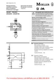
Figure 1: <strong>Representation</strong> <strong>of</strong> the tripping characteristic <strong>of</strong> different protective devices on the same time and current scale. The device data and settings are<br />
stated at the upper end <strong>of</strong> the curves.<br />
Fuse<br />
General specifications:<br />
Company: <strong>Moeller</strong> GmbH Bonn<br />
Installation: NSV Selektiv<br />
Editor: Max Mustermann<br />
Date: 13.11.2006<br />
Line: 415 V / 50 Hz<br />
Freely configurable<br />
characteristic<br />
For <strong>Moeller</strong> Electric Sales and Support call KMparts.com (866) 595-9616
individual project designations, can<br />
be saved, printed or exported to other<br />
documents. But also those who are<br />
familiar with the physical fundamental<br />
principles and particularities <strong>of</strong> the<br />
equipment, should spare the time to<br />
read the section entitled “Handling<br />
<strong>of</strong> the <strong>Moeller</strong> CurveSelect program<br />
V1.071 s<strong>of</strong>tware tool” and consider<br />
the advantages <strong>of</strong> the new tool.<br />
In addition, the unique ARCON ® arcfault<br />
protection system from <strong>Moeller</strong><br />
is briefly presented. The system which<br />
acts within a few milliseconds protects<br />
against fatal injuries and ruinous damage<br />
to the system. All conventional protective<br />
devices available on the market<br />
are simply too slow to effectively prevent<br />
damage caused by an arc-fault.<br />
This additional protection is particularly<br />
important when working under live<br />
conditions in special circumstances.<br />
Selection criteria for circuit-breakers<br />
- 4 main applications and personnel<br />
protection -<br />
Circuit-breakers provide the highest<br />
level <strong>of</strong> complexity with the setting <strong>of</strong><br />
their tripping characteristics among the<br />
protective devices in the low-voltage<br />
engineering field. The diverse setting<br />
possibilities are explained using the<br />
new NZM circuit-breaker as an example.<br />
The areas <strong>of</strong> application <strong>of</strong> the NZM<br />
circuit-breakers, with releases for overload<br />
and short-circuit currents and<br />
comprehensive system accessories,<br />
are also extremely diverse.<br />
NZM compact circuit-breakers (MCCB)<br />
are <strong>of</strong>fered by <strong>Moeller</strong> with electronic<br />
releases and with differing applicationdependent<br />
variables for rated operational<br />
currents between 15 and 1600 A.<br />
The smallest switch frame size, the<br />
NZM 1, and a simple standard variant <strong>of</strong><br />
the NZM 2 and NZM 3 frame size, do<br />
not feature an electronic release as they<br />
are exclusively equipped with electromechanical<br />
releases, intended as particularly<br />
attractively priced circuit-breakers<br />
and as the lowest non-delayed<br />
stage in a selectivity (discrimination)<br />
chain. Three switch frame sizes with the<br />
designations NZM 2, NZM 3 and NZM 4<br />
contiguously cover the current range up<br />
to 2000 A and partly overlap in their ranges,<br />
with versatile electronic releases. The<br />
Figure 2: The four frame sizes <strong>of</strong> the <strong>Moeller</strong> NZM compact circuit-breakers. Frame sizes NZM 1, NZM<br />
2 and NZM 3 feature a thermo mechanical and electromechanical release. The frame sizes NZM 2, NZM<br />
3 alternatively feature electronic releases as with the NZM 4 and the open circuit-breaker IZM as<br />
shown on the left.<br />
IZM open circuit-breakers (ICCB) are<br />
additionally <strong>of</strong>fered in three frame sizes<br />
for larger rated currents up to 6300 A<br />
(Figure 2). All switch frame sizes feature<br />
several variants with differing levels <strong>of</strong><br />
short-circuit breaking capacity. The prices<br />
<strong>of</strong> the switches reflect the shortcircuit<br />
breaking capacity performance<br />
as well as other features. As a result, the<br />
planning engineer can economically<br />
match the project-related switch rating<br />
to the required short-circuit rating <strong>of</strong><br />
the system. The selected switching<br />
capacity defines – corresponding to<br />
Figure 7 – the lower end <strong>of</strong> the tripping<br />
charac-teristic which is presented later.<br />
Table 1 indicates the type variants available<br />
using a 3-pole switch in the IEC<br />
version. The range also includes switches<br />
approved to the North American<br />
UL and CSA standards and the regional<br />
specific 4-pole circuit-breaker versions.<br />
The application-specific variants <strong>of</strong> the<br />
switch which are also indicated in<br />
Table 1 will also be described later.<br />
The NZM circuit-breakers presented are<br />
used with differing protective tasks in<br />
practically every type <strong>of</strong> low-voltage<br />
power distribution system as outgoing<br />
circuit-breakers. In small to medium<br />
sized distribution systems, they also<br />
serve as incoming circuit-breakers up<br />
to 2000 A. In addition to pure power<br />
1 MCCB = Molded Case Circuit Breaker<br />
2 ICCB = Insulated Case Circuit Breaker<br />
3 IEC = International Electrical Commission<br />
4 UL = Underwriter‘s Laboratories (http://www.ul.com)<br />
5 CSA = Canadian Standards Association (http://www.csa.ca)<br />
distribution tasks, the switches are<br />
used for the protection <strong>of</strong> various types<br />
<strong>of</strong> equipment against overload and<br />
short-circuit as well as for protection<br />
<strong>of</strong> the switchgear and the connecting<br />
cables and conductors and also in<br />
machines and system controls. They<br />
comprehensively master the four most<br />
important main application areas:<br />
protection <strong>of</strong> systems<br />
motor protection<br />
transformer protection and<br />
generator protection (Figure 3).<br />
Protection <strong>of</strong> systems is understood as<br />
the protection <strong>of</strong> cables and conductors<br />
as well as the protection <strong>of</strong> busbar<br />
systems. It is highly significant in<br />
switchgear systems for power distribution<br />
(distribution board) – and not to<br />
be neglected – for busbar trunking<br />
systems, the attractive alternative to<br />
cables. Protection <strong>of</strong> systems also<br />
includes the protection <strong>of</strong> the<br />
switchgear, protective devices and<br />
control circuit devices as well as the<br />
automation control systems installed in<br />
the switchgear systems. The motor protection,<br />
generator protection and transformer<br />
protection fields <strong>of</strong> application<br />
serve the specific protection <strong>of</strong> stated<br />
equipment types [1]. For optimum protection<br />
and economic use <strong>of</strong> this equipment,<br />
the tripping characteristics <strong>of</strong> the<br />
For <strong>Moeller</strong> Electric Sales and Support call KMparts.com (866) 595-9616<br />
3
4<br />
protective devices must be matched as<br />
precisely as possible, by the settings<br />
described later, to the individual performance<br />
<strong>of</strong> the equipment to be protected.<br />
Economically viable operation<br />
also means that the protective devices<br />
do not trip when not intended.<br />
In addition to these functions which<br />
are primarily intended to protect the<br />
equipment, the additional personnel<br />
protection demands should not be<br />
neglected. Personnel protection is<br />
implemented with all switch types as<br />
protection against electrical shock, by<br />
fast automatic shutdown <strong>of</strong> dangerous<br />
touch voltages. Sufficiently short tripping<br />
times must be ensured by the<br />
engineering and dimensioning <strong>of</strong> the<br />
switch, e.g. by the observance <strong>of</strong> the<br />
“protective multiple earthing conditions”<br />
(IEC / EN 60 364-4-41, VDE 0100<br />
Part 410) [2]. The following additional<br />
protective functions do not influence<br />
the necessary switch settings and tripping<br />
characteristic:<br />
some switch frame sizes feature<br />
➜<br />
c)<br />
b) ➜<br />
➜<br />
d)<br />
a) ➜<br />
Figure 3: The four main applications <strong>of</strong> the NZM compact circuit-breakers, for which IZM circuit-breakers are partly used with higher currents:<br />
a) protection <strong>of</strong> systems / line protection b) transformer protection c) motor protection d) generator protection<br />
optional, separately adjustable<br />
fault current or earth fault protective<br />
functions,<br />
on all frame sizes personnel<br />
protection is implemented by fast<br />
safety disconnection <strong>of</strong> outgoers<br />
and equipment,<br />
an additional protective function,<br />
the undervoltage protection, can<br />
be performed by the circuit-breaker<br />
if it is equipped with an undervoltage<br />
release,<br />
in this case they simultaneously<br />
guarantee the protection against<br />
automatic restart after an interruption<br />
<strong>of</strong> the voltage supply,<br />
all NZM and IZM circuit-breakers<br />
presented can provide main switch<br />
and isolating characteristics [3, 4].<br />
In the power distribution field, switchdisconnnectors<br />
and circuit-breakers are<br />
generally the most important switching<br />
and protective devices. At critical nodes<br />
in the electrical power supply which<br />
areresponsible for the power supply to<br />
entire factories or town districts, fuseless<br />
protection <strong>of</strong> the supply by circuitbreakers<br />
which are ready to restart<br />
quickly without the requirement for<br />
installation <strong>of</strong> spare parts are <strong>of</strong> primary<br />
importance. Selective or discriminative<br />
protection on various levels <strong>of</strong> the power<br />
network ensures a high level <strong>of</strong> system<br />
and process availability. This is understood<br />
to mean that only the protective<br />
device in the vicinity <strong>of</strong> the short-circuit<br />
will trip. The following are conventional<br />
switchgear combinations to implement<br />
selective (discriminative) networks:<br />
fuse – fuse,<br />
fuse – circuit-breaker,<br />
circuit-breaker – fuse,<br />
circuit-breaker – circuit-breaker.<br />
Figure 4 indicates an example for a<br />
network design with time selectivity<br />
(time-discriminating), which is achieved<br />
by using switches with differing shorttime<br />
delays for the short-circuit release.<br />
<strong>Moeller</strong> helps the practically-minded<br />
to find the optimum, selective<br />
engineering design – even including<br />
designs considering fuses – with the<br />
For <strong>Moeller</strong> Electric Sales and Support call KMparts.com (866) 595-9616
Type<br />
NetSelect or NetPlan planning s<strong>of</strong>tware.<br />
The <strong>Moeller</strong> NZM and IZM circuitbreakers<br />
with electronic releases can<br />
also be comfortably networked into<br />
modern switchgear systems [5].<br />
Dedicated s<strong>of</strong>tware tools are also<br />
available for networking tasks.<br />
Functional areas in the tripping<br />
characteristic and the thermal<br />
memory <strong>of</strong> the release<br />
Frame sizes, applications, switching capacity, setting range <strong>of</strong> the NZM circuit breaker,<br />
IEC-version, 3-pole switch<br />
Electromechanical release Electronic release<br />
<strong>Tripping</strong> characteristics indicate multiple<br />
function areas <strong>of</strong> the safety devices.<br />
Different releases installed in the same<br />
device are partly responsible for the<br />
differing functional areas. The tripping<br />
characteristic expresses the behaviour<br />
<strong>of</strong> a protective device dependant on the<br />
different levels <strong>of</strong> current flow and the<br />
times for which the currents are flo-<br />
IEC switching capacity at 400 V IEC switching capacity at 400 V<br />
B = 25 kA N = 50 kA H = 150 kA N = 50 kA H = 150 kA<br />
<strong>Setting</strong> ranges in A <strong>Setting</strong> ranges in A<br />
NZM..1 -A.. 15 - 160 15 - 160 15 - 160 * ) - - -<br />
NZM..1 -M.. 16 - 100 16 - 100 - - - -<br />
NZM..1 -S.. 40 - 100 40 - 100 40 - 100 - - -<br />
NZM..2 -A.. 100 - 250 100 - 250 15 - 250 - - -<br />
NZM..2 -M.. 100 - 200 100 - 200 16 - 200 -ME.. 45 - 220 45 - 220<br />
NZM..2 -S.. 125 - 200 125 - 200 40 - 200 - - -<br />
NZM..2 - - - - -VE.. 50 - 250 50 - 250<br />
NZM..3 - - - - -AE.. 125 - 630 125 - 630<br />
NZM..3 - - - - -ME.. 110 - 450 110 - 450<br />
NZM..3 - - - - -VE.. 125 - 630 125 - 630<br />
NZM..4 - - - - -AE.. 315 - 1600 315 - 1600<br />
NZM..4 - - - - -ME.. 275 - 1400 275 - 1400<br />
NZM..4 - - - - -VE.. 315 - 1600 315 - 1600<br />
* ) H = 100 kA<br />
-A.. Protection <strong>of</strong> systems and cables<br />
-M.. Motor protection<br />
-S.. Short-circuit protection (without overload protection)<br />
S1<br />
S2<br />
S3<br />
S4<br />
S5<br />
Hochspannung<br />
High voltage<br />
Low voltage<br />
Niederspannung<br />
A<br />
B<br />
C<br />
D<br />
-AE.. Protection <strong>of</strong> systems and cables<br />
-ME.. Motor protection<br />
-VE.. System and cable protection,<br />
selective and generator protection<br />
Table 1: Overview <strong>of</strong> the most important selection criteria for the NZM circuit-breakers and the solution with electromechanical or electronic releases.<br />
Minutes Minuten<br />
Milli-Sekunden Milliseconds<br />
Sekunden Seconds<br />
2h<br />
100<br />
40<br />
10<br />
4<br />
1<br />
40<br />
10<br />
4<br />
1<br />
400<br />
100<br />
40<br />
10<br />
4<br />
1<br />
S5 S4 S3<br />
250A 1000A 2000A<br />
S5<br />
S4<br />
S3<br />
tv<br />
50ms<br />
50ms<br />
100 200 400 1000 2000 4000 10000 20000<br />
ICC<br />
[A]<br />
Figure 4: Example <strong>of</strong> a cascade type network design. The switches on the various network levels<br />
should shutdown selectively. This can be implemented with time selectivity. The switch on the lowest<br />
level (S 5 in the example) features a non-delayed short-circuit release, all upstream switches have a<br />
short-delay time <strong>of</strong> about 50 ms, 100 ms etc.<br />
For <strong>Moeller</strong> Electric Sales and Support call KMparts.com (866) 595-9616<br />
5
6<br />
a b c<br />
t Ir<br />
tr<br />
Irmv<br />
Figure 5: The figure indicates a tripping characteristic with functional ranges<br />
1. Non-trip range / operating range to the left <strong>of</strong> or under the red tripping characteristic,<br />
2. Overload range, a brief overload is possible,<br />
3. Short-circuit range.<br />
The figure also indicates the variable parameters corresponding to Table 4, which enable applicationspecific<br />
design <strong>of</strong> the characteristic curve.<br />
wing. The tripping characteristic indicates<br />
the behaviour <strong>of</strong> a circuit-breaker<br />
under operational as well as under<br />
exceptional conditions. Constructive<br />
features <strong>of</strong> the circuit-breaker can have<br />
an influence on the specific tripping<br />
characteristic. The tripping characteristic<br />
must correspond with the demands<br />
<strong>of</strong> the equipment to be protected. A<br />
trip will not occur underneath or left<br />
<strong>of</strong> the tripping characteristic in the<br />
controlled admissible range. The<br />
current/time field underneath/left <strong>of</strong><br />
the tripping characteristic can be used<br />
operationally (operational conditions).<br />
For example, in this range drives will<br />
also operate intermittently resulting in a<br />
higher current (in the overload range)<br />
for a short time. The equipment and the<br />
protective devices can cool <strong>of</strong>f in the<br />
intermittent pauses. The field above or<br />
right <strong>of</strong> the tripping characteristic indicates<br />
the range for exceptional conditions<br />
with the faults possible due to an<br />
overload or short-circuit. The characteristic<br />
is generally represented as a loglog<br />
coordinate system. The characteristic<br />
covers three ranges as indicated in<br />
Figure 5:<br />
tv<br />
a Non-trip range<br />
In the first range, the switch will not<br />
trip without reason when the equipment<br />
is not endangered. For this reason,<br />
the switch may not trip within<br />
2 hours (at I ≤ 63 A, within 1 hour)<br />
when started from the cold state, and<br />
at the reference temperature when<br />
loaded on all poles with up to 1.05<br />
times the current setting I r for the<br />
current-dependant delayed overload<br />
release (conventional non-tripping<br />
current).<br />
b Overload range<br />
Irm<br />
The second range is the overload<br />
range. In this range the currentdependant<br />
thermal (bimetallic)<br />
or current-dependant electronic<br />
delayed overload release acts. With<br />
NZM circuit-breakers, the overload<br />
releases are always adjustable with<br />
the exception <strong>of</strong> special devices<br />
designed for the North American<br />
market. The tripping time is long<br />
with marginal overcurrents and<br />
becomes shorter with larger currents.<br />
This characteristic corresponds<br />
I<br />
with the load capability <strong>of</strong> the equipment<br />
to be protected. The permissible<br />
overcurrents cannot be increased<br />
as required, because the thermal and<br />
dynamic loading for the equipment,<br />
cabling, switchgear system and<br />
switches increase with the square <strong>of</strong><br />
the current (pay special attention to<br />
this fact when engineering for highinertia<br />
motors). The overload range<br />
extends up to the application relevant<br />
adjustable response range <strong>of</strong><br />
the magnetic short-circuit instantaneous<br />
release (comparable with<br />
an emergency brake). The range<br />
between factor 1.05 and the factor<br />
1.2 to factor 1.3 current setting value<br />
I r is defined as the current limit<br />
range. This range is <strong>of</strong> particular<br />
importance for standard-conform<br />
adjustment <strong>of</strong> the switch during<br />
manufacture. With electronic overload<br />
releases on the circuit-breakers,<br />
e.g. for the motor protection, the<br />
position <strong>of</strong> the curve on the time axis<br />
(t r ) can also be <strong>of</strong>fset to take heavy<br />
starting duty into consideration. The<br />
set time t r applies for 6 times the current<br />
setting I r . The designation “tripping<br />
class” (Class 5, 10, 20, etc.) is<br />
know for a similar function with the<br />
electronic motor-protective relay,<br />
and allows the max. tripping time<br />
at 7.2 times the current setting I r .<br />
On relays the standard setting is Class<br />
10 A with t r = 10 s.<br />
The short-circuit circuit-breakers<br />
without overload release are a special<br />
type. This switch is combined<br />
with additional overcurrent protective<br />
devices. These combinations are<br />
selected for the protection <strong>of</strong> motors<br />
with extended start-up times or<br />
when the circuit-breaker is not supposed<br />
to trip with a self-correcting<br />
overload. This type <strong>of</strong> switch is found<br />
more frequently in North America<br />
than in the IEC world.<br />
c Short-circuit range<br />
The permissible overload limit for<br />
the equipment and the switch are<br />
exceeded here. This is where the<br />
short-circuit range commences<br />
where the non-permissible current<br />
should be shutdown as soon as<br />
possible. The response value <strong>of</strong><br />
the short-circuit release I i (i = instan-<br />
For <strong>Moeller</strong> Electric Sales and Support call KMparts.com (866) 595-9616
taneous) is selected as a multiple<br />
<strong>of</strong> the rated current <strong>of</strong> the switch I n<br />
(highest current setting). This multiple<br />
can be set to suit the application,<br />
i.e. the type <strong>of</strong> equipment to be<br />
protected. If the rated current <strong>of</strong> the<br />
switch is not fully exploited, the<br />
multiple setting at which the switch<br />
trips is larger than the multiple setting<br />
which is set on the switch. If for<br />
example motors are being protected,<br />
the response value <strong>of</strong> the short-circuit<br />
release must be selected so that<br />
it is not tripped by the inrush current<br />
peak (starting current). In this case<br />
and with the protection <strong>of</strong> transformers,<br />
it is <strong>of</strong>ten more useful when<br />
the circuit-breaker does not have to<br />
be set to the highest level. This <strong>of</strong>fers<br />
additional security against premature<br />
tripping, which can be particularly<br />
important when the response value<br />
<strong>of</strong> a short-circuit release is not adjustable.<br />
Depending on the switch type,<br />
a differentiation is made between<br />
non-delayed (I i ) and short-time<br />
delayed (I sd ) short-circuit releases.<br />
A short-time delayed short-circuit<br />
release is always combined in the<br />
same switch with a (higher setting)<br />
non-delayed short-circuit release.<br />
Suitability for main and secondary applications,<br />
<strong>of</strong> the switch in the IEC version<br />
Main applications Secondary application Type<br />
Short-circuit<br />
protection<br />
(without overload<br />
release)<br />
System<br />
protection<br />
Cable<br />
protection<br />
Generator<br />
protection<br />
Selective<br />
protection<br />
with delayed<br />
short-circuit<br />
release<br />
Motor<br />
protection<br />
Main<br />
switch<br />
With delayed releases, the current<br />
and the additional delay time (t sd )<br />
must be set to suit the specifications<br />
<strong>of</strong> the equipment to be protected.<br />
The delay time starts when the set<br />
current <strong>of</strong> the delayed release is<br />
exceeded. Before a trip is initiated,<br />
the unit verifies if the set current still<br />
exceeds the threshold value. The<br />
set delay time is independent <strong>of</strong> the<br />
current. The higher setting on the<br />
non-delayed instantaneous shortcircuit<br />
release (I i ) trips the switch if<br />
its setting value is exceeded during<br />
the delay time. The non-delayed<br />
short-circuit release is the emergency<br />
brake in this combination.<br />
With a cascade-like selective (discriminative)<br />
network design, the downstream<br />
circuit-breaker in the vicinity<br />
<strong>of</strong> the fault must trip within the<br />
delay time <strong>of</strong> the upstream circuitbreaker<br />
in order to reduce/interrupt<br />
the current in good time, otherwise<br />
there is a danger that the upstream<br />
delayed circuit-breaker will also trip.<br />
Always when delayed releases for<br />
the circuit-breaker or higher tripping<br />
times with overload relays<br />
(e.g. Class 40) are used, for exam-<br />
Emergency<br />
stop<br />
X X N..-..<br />
yellow and “E” =<br />
electronic release<br />
green = electro-mechan.<br />
release<br />
X (X) * X X NZM.. ..-S..<br />
X X X X NZM.. ..(-4)-A..<br />
X X X X NZM.. ..(-4)-AE..<br />
X (X) ** (X) ** NZM.. ..-M..<br />
X (X) ** (X) ** NZM.. ..-ME..<br />
X X X X X X NZM.. ..(-4)-VE..<br />
* Only in combination with suitable contactor and overload relay<br />
** Only for single motor starter<br />
(-4) Type suffix for 4-pole switch<br />
Table 2: Application dependant main and secondary applications <strong>of</strong> the NZM circuit-breaker with electromechanical or electronic releases.<br />
ple with heavy starting duty <strong>of</strong><br />
large motors, the design engineer<br />
must consider that all devices and<br />
cables in the entire circuit are subject<br />
to a higher current load for an<br />
extended period <strong>of</strong> time. In such<br />
cases, it is frequently the case that<br />
the switchgear and the cables<br />
must be overdimensioned accordingly.<br />
An important feature for protection <strong>of</strong><br />
equipment and cables is the “thermal<br />
memory” <strong>of</strong> the release. The thermal<br />
memory simulates the heating effects <strong>of</strong><br />
the equipment to be protected during<br />
normal operation and during the overload<br />
phase. It permanently saves the<br />
heating factors to ensure that the<br />
thermal state <strong>of</strong> the equipment is still a<br />
known factor after trip <strong>of</strong> a switch or<br />
after a voltage loss. This provides the<br />
basis for a further, optimum protection<br />
feature after an interruption in operation<br />
or with an intermittent operational<br />
characteristic. The thermal memory<br />
takes the typical time constant for cooling<br />
<strong>of</strong> the load (cable or motor) into<br />
consideration when dissipating the stored<br />
heat which has thermally loaded the<br />
cable or motor.<br />
For <strong>Moeller</strong> Electric Sales and Support call KMparts.com (866) 595-9616<br />
7
8<br />
The emulation <strong>of</strong> the cooling is implemented<br />
on the electronic releases using<br />
the same time constant with which the<br />
heating characteristic is determined.<br />
On bimetal releases this function results<br />
automatically as the heated bimetals<br />
must cool down to return to their initial<br />
states. During operation, the thermal<br />
memory prevents the load, e.g. a motor,<br />
being subject to a thermal overload<br />
after an overload release caused by a<br />
Feature<br />
Relevant standards<br />
Current limit range<br />
Ambient temperature<br />
Conventional non-tripping current *)<br />
for the current dependant delayed<br />
trip<br />
(May not trip within 2 h **), with load on all<br />
poles, at reference temperature)<br />
Conventional tripping current *)<br />
for the current dependant delayed<br />
trip<br />
(Must be within 2 h **), according to load<br />
with the non-tripping current)<br />
Single-phasing sensitivity<br />
Definition:<br />
May not trip within 2 h at:<br />
Must trip within 2 h at:<br />
Response range <strong>of</strong> the short-circuit<br />
release (Empirical values)<br />
I r = setting <strong>of</strong> the overload release<br />
Immunity to starting current<br />
Selectivity<br />
Overcurrent release<br />
<strong>Tripping</strong> class<br />
Thermal memory<br />
restart before it has cooled sufficiently.<br />
At the same time, the preheating <strong>of</strong> the<br />
equipment is taken into consideration<br />
by the thermal memory if an overload<br />
occurs. A restart is only possible when<br />
the electronic simulation or the reverse<br />
bending process <strong>of</strong> the bimetals indicates<br />
that the motor is sufficiently cool.<br />
If unfavourable cooling conditions are<br />
to be expected and the motor heats<br />
Different demands placed on the circuit-breaker<br />
for system and motor protection<br />
Protection <strong>of</strong> systems<br />
IEC / EN 60 947-1 [6]<br />
IEC / EN 60 947-2 [7]<br />
Manufacture specified<br />
40 °C (at <strong>Moeller</strong>)<br />
1.05 x current setting<br />
**) 1 h at ≤ 63 A<br />
1.30 x current setting<br />
**) 1 h at ≤ 63 A<br />
Not intended<br />
Not useful as the current loading<br />
on the phase can be unbalanced<br />
and frequently is<br />
approx. 6...10 x I r<br />
Conditional requirement<br />
With multiple switches in series<br />
usually required<br />
Must not be adjustable<br />
(Always adjustable with NZM and IZM)<br />
Not intended<br />
Useful<br />
up more quickly / cools down with a greater<br />
delay than considered by the simulation,<br />
the motor will require additional<br />
protection using a thermistor temperature<br />
detector and an EMT 6 evaluation<br />
unit.<br />
Motor protection<br />
IEC / EN 60 947-1 [6]<br />
IEC / EN 60 947-4-1 [8]<br />
Standard value<br />
20 °C<br />
1.05 x current setting<br />
1.20 x current setting<br />
Alternative permissible<br />
Useful protective function, as the<br />
current distribution <strong>of</strong> the phases<br />
with motors should be symmetric<br />
2 pole 1.0 x current setting,<br />
1 pole 0.9 x current setting<br />
2 pole 1.15 x current setting,<br />
1 pole 0 x current setting<br />
approx. 8...14 x I r<br />
Required<br />
Useful<br />
Adjustable<br />
Useful For matching to the<br />
start-up behaviour <strong>of</strong> the motor<br />
Essential requirement<br />
Table 3: Different demands with both high sales applications <strong>of</strong> the circuit-breaker, the “protection <strong>of</strong> systems” conform to IEC / EN 60 947-2 [7] and the<br />
“motor protection” conform to IEC / EN 60 947-4-1 [8]<br />
*) Definitions are informative but are only used in the IEC / EN 60 947-2 **) Refer to second column<br />
For <strong>Moeller</strong> Electric Sales and Support call KMparts.com (866) 595-9616
Necessity for variable tripping<br />
characteristics with modern<br />
circuit-breakers<br />
The specific protective tasks and the<br />
application related operating conditions<br />
(utilization categories) <strong>of</strong> the stated<br />
equipment demand differing switch<br />
settings. This relationship leads through<br />
the different, adjustable variables to<br />
application-specific switch variants,<br />
corresponding to those in Tables 1 and<br />
2. The demands placed on the spectrum<br />
<strong>of</strong> adjustment possibilities increase<br />
when multiple protective devices are<br />
connected in series. This is always the<br />
case especially when several main distribution<br />
and sub-distribution boards<br />
are arranged between the low-voltage<br />
incomer transformer and the equipment.<br />
In these cases, the switches and<br />
the cables and conductors for the individual<br />
segments <strong>of</strong> the circuit must<br />
frequently be dimensioned for different<br />
current levels. As a result, switches <strong>of</strong><br />
varying frame size are <strong>of</strong>ten connected<br />
in series in the current path.<br />
The four listed fields <strong>of</strong> application<br />
place different demands on the switch<br />
as indicated in the example for system<br />
and motor protection in Table 3.<br />
The most important application-dependant<br />
parameters for the circuit-breaker<br />
selection are<br />
occurrence <strong>of</strong> a symmetrical or<br />
unsymmetrical load,<br />
different, typical inrush peak currents<br />
<strong>of</strong> the equipment to be protected<br />
with their differing current/dynamic<br />
response,<br />
normal operating currents,<br />
prospective overload currents with<br />
their differing current/dynamic<br />
response and<br />
finally, the level <strong>of</strong> the short-circuit<br />
currents which are to be expected.<br />
With the short-circuit currents, it is not<br />
only the obvious question that is posed<br />
concerning the maximum current levels,<br />
but also if the currents expected during<br />
a malfunction exceed the overload<br />
range in the short-circuit range in order<br />
to trip the switch with the necessary<br />
speed to prevent damage to the downstream<br />
equipment and injury to personnel.<br />
The question <strong>of</strong> adequate current<br />
levels is mainly an issue with low-power<br />
generators or in circuits with long cable<br />
lengths, which result in a high line<br />
impedance and a high voltage drop. For<br />
this reason, a generator circuit-breaker<br />
with a particularly low setting is available.<br />
However, fast shutdown during a<br />
malfunction is a time-critical operation<br />
for personnel protection with the<br />
dangerous touch voltages which result.<br />
However, during a short-circuit it is<br />
possible that unintended high level<br />
voltage drops occur which can cause<br />
undefined switching states in the<br />
contactor relays or on the voltage<br />
dependant releases in the system,<br />
and which also require a fast shortcircuit<br />
trip. Undervoltage releases<br />
can assist here.<br />
The tool presented in this paper enables<br />
simple representation <strong>of</strong> tripping<br />
characteristics, for known (selected)<br />
switches on a PC and the simple visual<br />
comparison <strong>of</strong> the characteristic curves<br />
<strong>of</strong> multiple switches and fuses, which<br />
are connected in series in the current<br />
path at various levels in the network<br />
(Figure 4). The objective is to verify if<br />
the switches provide safe operation and<br />
if the selectivity exists between the<br />
protective devices used in the overload<br />
and short-circuit range. The most significant<br />
advantage <strong>of</strong> this tool compared<br />
to every printed representation in<br />
a catalogue is that the very specific<br />
trip characteristic which takes<br />
account <strong>of</strong> all the actual settings on<br />
the switch, can be generated and<br />
documented. A prerequisite for the<br />
correctness <strong>of</strong> the curve is that identical<br />
switch types are selected in the tool<br />
and the switchgear system, and that all<br />
the switch position settings are correctly<br />
entered into the tool. If the tool<br />
indicates that modified settings are<br />
required on the switch, the required<br />
settings must be made manually on the<br />
switches. All results can be saved,<br />
copied and printed including details for<br />
identifying the devices.<br />
In addition to the trip characteristics<br />
for the presented new NZM 1 to NZM 4<br />
compact circuit-breakers, the tool can<br />
also display the characteristics for the<br />
previous generation <strong>of</strong> compact devices<br />
such as the NZM 7, NZM 10 and NZM<br />
14, as well as the IZM 1 to IZM 3 open<br />
circuit-breakers and the fuses with<br />
gl-characteristic. The tool will be<br />
expanded in the future to include<br />
further components such as the PKZM<br />
motor-protective circuit-breaker and<br />
ZB overload relay.<br />
Constants and variables for curve<br />
representation<br />
Protective devices with bimetal releases<br />
such as the ZB 12, ZB 32 , ZB 65 or<br />
ZB 150 overload relay only allow for<br />
setting <strong>of</strong> the rated motor current as<br />
the current setting I r <strong>of</strong> the overload<br />
release. The further response characteristic<br />
<strong>of</strong> the trip characteristics is defined<br />
in the construction phase by the rating<br />
<strong>of</strong> the bimetal, so that the bimetal characteristic<br />
corresponds as accurately as<br />
possible to the heat characteristic <strong>of</strong> the<br />
motors. The only non-adjustable sidebenefit<br />
<strong>of</strong>fered by this variant is a standard-conform<br />
single-phasing sensitivity,<br />
and all variants feature ambient temperature<br />
compensation. They detect and<br />
take the failure <strong>of</strong> any main pole (phase)<br />
into consideration. The same applies for<br />
PKZM 01, PKZM 0 and PKZM 4 motorprotective<br />
circuit-breakers. On these<br />
circuit-breakers the response ranges <strong>of</strong><br />
the additional short-circuit release are<br />
fixed. The PKZ 2 system and motorprotective<br />
circuit-breaker take a further<br />
step on the development front as the<br />
response ranges <strong>of</strong> the magnetic shortcircuit<br />
releases are adjustable here.<br />
The NZM 1 circuit-breaker and thermomagnetic<br />
circuit-breakers NZM 2 and<br />
NZM 3 are directly comparable with<br />
these protective devices.<br />
Protective devices with electronic<br />
releases such as the NZM 2 to 4 or IZM 1<br />
to 3 <strong>of</strong>fer additional degrees <strong>of</strong> freedom<br />
with the setting and definition <strong>of</strong><br />
their protective features as well as in<br />
conjunction with further protective<br />
devices present in the same circuit.<br />
Table 4 indicates effective parameters<br />
with differing protective switch types,<br />
which are either fixed or variable settings.<br />
The opportunity to match these<br />
individual settings to the varying equipment<br />
is a significant advantage <strong>of</strong><br />
circuit-breakers in comparison to fuses.<br />
An example <strong>of</strong> the improved protective<br />
features by individual adjustable electronic<br />
releases is indicated by Figure 6<br />
which is a typical motor start-up characteristic,<br />
which can now be represented<br />
using the tool, and the protection, on<br />
the one hand with a circuit-breaker<br />
with thermal overload releases on<br />
For <strong>Moeller</strong> Electric Sales and Support call KMparts.com (866) 595-9616<br />
9
10<br />
<strong>Setting</strong> possibilities with current-dependant acting releases with different circuit-breaker types<br />
Parameters with influence on the<br />
tripping characteristic<br />
which a short-circuit release is set to the<br />
maximum current, as well as significantly<br />
improved protection with circuitbreaker<br />
electronic releases on the other<br />
hand. In the first case, the peak inrush<br />
current can still cause a trip release <strong>of</strong><br />
the switch. In the second case the motor<br />
has better protection during run-up.<br />
The adjustable fault current or earthfault<br />
releases are optional accessories<br />
The releases can be optionally available or the specifications only apply<br />
with certain switch variants, see latest <strong>Moeller</strong> main catalogue<br />
Electromechanical release Electronic release<br />
Type ZB... PKZM... PKZ... NZM... NZM... IZM...<br />
Size<br />
12, 32,<br />
65, 150<br />
<strong>Setting</strong> I r for overload release var. var. var.<br />
Response value I rm for instantaneous<br />
short-circuit release<br />
Response value I i for instantaneous<br />
short-circuit release<br />
Response value Isd for delayed<br />
short-circuit release<br />
which are not considered in the characteristics<br />
program. As already described,<br />
the short-time delayed switch enables<br />
the implementation <strong>of</strong> a time-discriminating<br />
system concept. The short-time<br />
delayed releases are also used on<br />
motors with extended run-up times. In<br />
this application the protective function<br />
can be extended to include the additional<br />
EMT6 thermistor machine protection<br />
relay from <strong>Moeller</strong>.<br />
01, 0, 4 2 1, 2 2 3, 4 1, 2, 3<br />
- fixed var.<br />
var.<br />
-<br />
fixed<br />
var.<br />
- - - -<br />
- - - - var.<br />
Handling <strong>of</strong> the <strong>Moeller</strong><br />
“CurveSelect” V1.071<br />
s<strong>of</strong>tware tool<br />
var. var.<br />
- -<br />
fixed fixed<br />
var. var.<br />
Motor protection tripping class CLASS fixed fixed fixed fixed var. -<br />
Time delay setting to overcome current peaks t r<br />
for overload release<br />
Delay time tsd for short delayed<br />
short-circuit release<br />
- - - -<br />
var.<br />
fixed fixed<br />
var. var.<br />
- - - - var. var.<br />
I 2 t-constant function - - - -<br />
Single-phasing sensitivity fixed fixed<br />
Rated fault current I Δn - - - -<br />
Delay time t v for residual-current release - - - -<br />
fixed fixed<br />
var. var.<br />
- - - -<br />
fixed fixed fixed fixed<br />
fixed -<br />
var. -<br />
fixed -<br />
var. -<br />
Response value I g for earth-fault release - - - - - var. var.<br />
Delay time t g for earth-fault release - - - - - var. var.<br />
Table 4: Fixed and variable parameters for current-dependant acting releases with different circuit-breaker types.<br />
Up to now, it was difficult to represent<br />
individual characteristic curves and to<br />
compare them with one another. Quiet<br />
<strong>of</strong>ten the comparison failed due to the<br />
differing scales for the representation<br />
<strong>of</strong> the coordinates <strong>of</strong> the curves for<br />
circuit-breakers and fuses. This has<br />
For <strong>Moeller</strong> Electric Sales and Support call KMparts.com (866) 595-9616<br />
-<br />
-<br />
-
<strong>Tripping</strong> time<br />
now changed with the new s<strong>of</strong>tware<br />
tool. All curves are now displayed on<br />
a single sheet enabling simple visual<br />
evaluation.<br />
The handling is very simple as the user<br />
is <strong>of</strong>fered the permissible variables in<br />
the type-specific input sheets. He simply<br />
has to enter the respective variable<br />
manually into the mask. The program is<br />
available for download on the Internet<br />
at www.moeller.net/de/support. Free <strong>of</strong><br />
charge registration is required with the<br />
program.<br />
1. The program is copied onto a PC<br />
as an Excel file on which Micros<strong>of</strong>t<br />
Excel ® is already installed.<br />
Further installation is not required.<br />
The file can be used for as many<br />
projects are required.<br />
2. The file is opened by a doubleclick<br />
on “Kennlinien... .xls”.<br />
An Excel worksheet opens with the<br />
multiple sheets required for the<br />
necessary inputs and the representation<br />
<strong>of</strong> the curves.<br />
<strong>Tripping</strong> diagram<br />
<strong>Tripping</strong> current [A]<br />
Figure 6: Circuit-breakers with electronic releases enable – by flexible setting features – a more exact matching to the typical current consumption curve <strong>of</strong><br />
a starting three-phase motor than is possible with the switch on thermal overload releases.<br />
3. Comprehensive, advanced information<br />
about the program is contained<br />
in the “Read Me” sheet.<br />
4. The required language versions<br />
can be selected in the “General”<br />
sheet. On this sheet “General<br />
details” <strong>of</strong> the project are entered<br />
and are automatically accepted<br />
into the representation <strong>of</strong> the<br />
characteristic curves.<br />
With version 1.071 <strong>of</strong> the program,<br />
it is only currently possible to use<br />
applications with an operating<br />
voltage <strong>of</strong> between 240 and 690 V,<br />
50...60 Hz.<br />
5. It is recommended that you save<br />
the program after entering the<br />
basic program data in any desired<br />
folder with “File” / “Save as”.<br />
This ensures that the original program<br />
file “Kennlinien... .xls” is available<br />
for further use and does not<br />
contain project-specific entries. It is<br />
also recommended that you save<br />
further entries regularly with “File” /<br />
“Save as”.<br />
General specifications:<br />
Company: <strong>Moeller</strong> GmbH<br />
Installation:<br />
Editor:<br />
Date:<br />
Line: 400V / 50Hz<br />
Motor starting curve<br />
<strong>Tripping</strong> characteristic<br />
<strong>of</strong> circuit-breaker with<br />
thermal releases<br />
Circuit-breakers with<br />
electronic releases<br />
6. With the worksheets “NZM...”,<br />
“IZM...”, “PKZ…”, “ZB”, “MCB”<br />
circuit-breakers or “Fuses” you<br />
can select the protective device<br />
whose characteristic curve you<br />
want to represent next.<br />
Per sheet and project it is possible to<br />
register the data for 2 to 3 protective<br />
devices <strong>of</strong> the same construction<br />
type and size in the “Input”<br />
fields. Every product sheet is used a<br />
maximum <strong>of</strong> once per project. All<br />
entries can be erased or overwritten<br />
if required. The respective permissible<br />
entries are provided corresponding<br />
to the selected basic type in the<br />
“Permissible setting range” field.<br />
The permissible values cant be<br />
copied and must be entered manually<br />
into the input fields. Invalid<br />
entries are indicated in the “Errors”<br />
field. If possible, an information<br />
display indicating “Control and<br />
limit values” and “Warnings” will<br />
be indicated if necessary.<br />
Each tripping characteristic can<br />
only be graphically represented<br />
For <strong>Moeller</strong> Electric Sales and Support call KMparts.com (866) 595-9616<br />
11
12<br />
when the device has been assigned<br />
with a designation in the<br />
“Designation” field.<br />
7. On the worksheets “FSC” (Free<br />
style curves) and “Mot” (Motor<br />
curves) the freely definable characteristics<br />
for protective devices<br />
or for a motor run-up curve are<br />
entered. Refer to the Read_Me file<br />
for further information concerning<br />
the handling <strong>of</strong> the freely definable<br />
curves. The freestyle curves are multiple<br />
usage oriented and can be<br />
reused by simply saving the project<br />
under different names.<br />
After entering the data for the<br />
first protective device and after<br />
each further input, the tripping<br />
characteristic(s) are displayed on<br />
the “<strong>Tripping</strong> graphs Curves”<br />
(Figure 1). Subsequent changes to<br />
the entries on the “Product sheets”<br />
are automatically considered by<br />
the next curve display. The representation<br />
is made on a log-log<br />
coordinate system with 5 x 7<br />
decades, from 1 A to 100 kA<br />
and from 1 ms to 2 h, and as<br />
absolute values.<br />
8. The entire worksheet or just<br />
the “Characteristics Curves”<br />
can be printed. The project related<br />
data can be displayed, edited and<br />
Start <strong>of</strong> the<br />
electrodynamic<br />
range<br />
printed on every computer where<br />
Excel is installed. The “Characteristics<br />
Curves” worksheet can<br />
be marked and copied into the computer<br />
clipboard and then inserted<br />
into other documents. After modifications<br />
on the input sheets, the<br />
“Characteristics Curves” sheet<br />
must be copied and inserted again<br />
if required.<br />
9. After completion <strong>of</strong> the project<br />
specific file, it can be protected by<br />
the write protect feature in Windows<br />
Explorer ® if required. (Locate<br />
and mark the file in Windows<br />
Explorer and then protect with<br />
“Properties” / “Attributes” / “Read-<br />
Only”.) It is recommended that you<br />
save the “Characteristics Curves”<br />
individually with a suitable s<strong>of</strong>tware<br />
package as a PDF file and to writeprotect<br />
it if necessary. This saves<br />
memory in the project folder and<br />
the document can be protected<br />
against subsequent modifications.<br />
10. The following limiting conditions<br />
must be observed with the evaluation<br />
<strong>of</strong> the diagrams:<br />
All curves are represented assuming<br />
the cold state and without representation<br />
<strong>of</strong> the standard-conform tolerances<br />
<strong>of</strong> the response ranges, and<br />
the tripping times are represented<br />
as mean values <strong>of</strong> the parameterized<br />
tripping characteristic.<br />
This representation corresponds<br />
with the characteristics represented<br />
in the catalogues. In the nondelayed<br />
overload release range,<br />
the minimum command duration is<br />
indicated as it is the time for which<br />
the current must flow before an<br />
irreversible trip is initiated. This<br />
corresponds to the melting time<br />
(minimum melting curve) with fuses.<br />
The current, voltage and the phase<br />
position dependent total opening<br />
delay, which is comprised <strong>of</strong> the<br />
response delay, switching delay and<br />
arc quenching time is not considered<br />
by the represented curves.<br />
11. In order to ensure selectivity (discrimination)<br />
in the overload range,<br />
the curves represented for the<br />
circuit-breaker under one another,<br />
and the curves for the fuses may<br />
not cross or touch each other at any<br />
point. Consider the tolerances <strong>of</strong><br />
the curves which are ± 20 % in the<br />
overload range. The overload selectivity<br />
(discrimination) <strong>of</strong> the selected<br />
devices has been reached at the<br />
meeting and crossover points.<br />
In the short-circuit range, the electrodynamic<br />
processes which are<br />
dependent on the individual switch<br />
construction play an important role.<br />
300 400 500 700 1k 1,2k 1,5k 2k 2,5k 3k 4k 5k 7k 10k 12k 15k 20k 25k 30k 40k 50k 70k 100k<br />
<strong>Tripping</strong> current [A]<br />
Characteristic end<br />
with I cu<br />
Figure 7: On the lower end range <strong>of</strong> the curves, a dynamic behaviour <strong>of</strong> the switch cannot be calculated with a reasonable amount <strong>of</strong> effort. For a binding<br />
statement regarding selectivity in this range, you are referred to the test results in the selectivity table in the <strong>Moeller</strong> main catalogue.<br />
For <strong>Moeller</strong> Electric Sales and Support call KMparts.com (866) 595-9616
<strong>Tripping</strong> time<br />
2h<br />
1h<br />
20min<br />
10min<br />
5min<br />
2min<br />
1min<br />
20s<br />
10s<br />
5s<br />
2s<br />
1s<br />
500ms<br />
200ms<br />
100ms<br />
50ms<br />
20ms<br />
10ms<br />
5ms<br />
2ms<br />
1ms<br />
2h<br />
1h<br />
20min<br />
10min<br />
5min<br />
2min<br />
1min<br />
20s<br />
10s<br />
5s<br />
2s<br />
1s<br />
500ms<br />
200ms<br />
100ms<br />
50ms<br />
20ms<br />
10ms<br />
5ms<br />
2ms<br />
1ms<br />
F2<br />
gl<br />
80A<br />
F1<br />
gl<br />
100A<br />
Q2<br />
NZMN3 -<br />
VE630<br />
In = 630A<br />
Ir = 1 x In<br />
tr = 2s<br />
Isd = 2 x Ir<br />
tsd = 0ms<br />
I≤t =On<br />
Ii = 8 x In<br />
Q1<br />
IZMB1 -<br />
U1600<br />
In = 1600A<br />
Ir = 1 x In<br />
tr = 8s (I≤t)<br />
Isd=3xIn<br />
tsd = 100ms<br />
I≤t =On<br />
Ii = 12 x In<br />
Allgemeine Angaben:<br />
Firma: General <strong>Moeller</strong> specifications:<br />
Company: <strong>Moeller</strong> GmbH<br />
Anlage: 1<br />
Installation: 1<br />
Bearb.: Editor: Mey Mey<br />
Datum: Date: 13.07.2007<br />
Netz: Line: 400V 400V / 50Hz / 50Hz<br />
10 12 15 20 25 30 40 50 70 100 120 150 200 250 300 400 500 700 1k 1,2k 1,5k 2k 2,5k 3k 4k 5k 7k 10k 12k 15k 20k 25k 30k 40k 50k 70k 100k<br />
Für die Richtigkeit übernimmt <strong>Moeller</strong> keine Gewähr.<br />
Die Haftung ist insoweit mit Ausnahme in Fällen des<br />
Vorsatzes ausgeschlossen.<br />
Figure 8: Non-selective protective devices can be recognised by crossover or (almost) touching curves. The green curve represents an IZM outgoing circuitbreaker<br />
in a distribution board. The NZM incoming circuit-breaker <strong>of</strong> a downstream sub-distribution is represented in blue. In this distribution circuit the<br />
fuses indicated in red are intended to protect various motor starters with overload relays.<br />
<strong>Tripping</strong> time<br />
F2<br />
gl<br />
80A<br />
F1<br />
gl<br />
100A<br />
Q2<br />
NZMN3 -<br />
VE630<br />
In = 630A<br />
Ir = 1 x In<br />
tr = 2s<br />
Isd=2xIr<br />
tsd = 300ms<br />
I≤t =On<br />
Ii = 8 x In<br />
Q1<br />
IZMB1 -<br />
U1600<br />
In = 1600A<br />
Ir = 1 x In<br />
tr = 8s (I≤t)<br />
Isd = 3 x In<br />
tsd = 100ms<br />
I≤t =On<br />
Ii = 12 x In<br />
Allgemeine Angaben:<br />
Firma: General <strong>Moeller</strong> specifications:<br />
Company: <strong>Moeller</strong> GmbH<br />
Anlage: 1<br />
Installation: 1<br />
Bearb.: Editor: Mey Mey<br />
Datum: Date: 13.07.2007<br />
Netz:<br />
Line:<br />
400V<br />
400V<br />
/ 50Hz<br />
/ 50Hz<br />
10 12 15 20 25 30 40 50 70 100 120 150 200 250 300 400 500 700 1k 1,2k 1,5k 2k 2,5k 3k 4k 5k 7k 10k 12k 15k 20k 25k 30k 40k 50k 70k 100k<br />
Für die Richtigkeit übernimmt <strong>Moeller</strong> keine Gewähr.<br />
Die Haftung ist insoweit mit Ausnahme in Fällen des<br />
Vorsatzes ausgeschlossen.<br />
Non-selective<br />
range<br />
<strong>Tripping</strong> diagram<br />
<strong>Tripping</strong> current [A]<br />
<strong>Tripping</strong> diagram<br />
<strong>Tripping</strong> current [A]<br />
Activated<br />
I 2 t function<br />
Figure 9: In contrast to Figure 8, the circuit-breaker represented in blue has been reselected. The modified settings provide selectivity in the overload<br />
and short-circuit range. The selectivity which is evident in the short-circuit range is confirmed by the selectivity specifications in the main catalogue. The I 2 t<br />
function can be switched on and <strong>of</strong>f. It improves the selectivity with fuses.<br />
For <strong>Moeller</strong> Electric Sales and Support call KMparts.com (866) 595-9616<br />
13
14<br />
The current limiting properties <strong>of</strong><br />
the circuit-breaker, owing to the<br />
electrody-namic effects on the<br />
contacts and quenching systems,<br />
can not be calculated with justifiable<br />
effort by this simple tool in the high<br />
current range. The range <strong>of</strong> this<br />
electro-dynamic limit is represented<br />
on the diagram by the response<br />
value <strong>of</strong> the non-delayed overload<br />
release using a dashed vertical line<br />
(Figure 7). The short-circuit selectivity<br />
is verified by comprehensive<br />
short-circuit testing in the test laboratory.<br />
For this range the details<br />
concerning the selectivity in the<br />
selectivity tables in the <strong>Moeller</strong> main<br />
catalogue are obligatory. The characteristic<br />
<strong>of</strong> the respective circuitbreaker<br />
ends with the value <strong>of</strong> the<br />
ultimate short-circuit breaking<br />
capacity I cu which depends on the<br />
device type and rated voltage.<br />
12. Selectivity problems can normally<br />
be remedied by selecting another<br />
device or sometimes by modified<br />
device settings (Figures 8 and 9).<br />
Enhanced protection in marginal<br />
conditions<br />
At the end <strong>of</strong> the nineties, <strong>Moeller</strong><br />
introduced the protection systems<br />
cone model for representation <strong>of</strong> the<br />
systematics with the protective systems<br />
[9]. <strong>Moeller</strong> arranges well known as<br />
well as innovative protection systems<br />
to the standard definitions or self-<br />
F Protection <strong>of</strong> installation<br />
functions<br />
E Protection <strong>of</strong> installations<br />
D Protection <strong>of</strong> equipment<br />
C Basic protection <strong>of</strong><br />
equipment<br />
B Protection <strong>of</strong> special<br />
installations and locations<br />
A Protection <strong>of</strong> persons<br />
Figure 10: <strong>Moeller</strong> represents the different protection systems in low-voltage engineering as a<br />
cone-shaped model. The functions and systems <strong>of</strong> functional protection extend beyond the functions<br />
<strong>of</strong> the circuit-breakers presented. <strong>Moeller</strong> solves these demands for example with the unique ARCON ®<br />
arc-fault protection system.<br />
created definitions corresponding<br />
with Figure 10.<br />
Definitions such as personnel protection,<br />
protection for special workshops<br />
and areas as well as protection <strong>of</strong><br />
equipment and the protection <strong>of</strong><br />
systems are generally well known.<br />
However new definitions are<br />
equipment basic protection and system<br />
functional protection. In the system<br />
protection field, <strong>Moeller</strong> has taken an<br />
indisputable lead with a new technology<br />
which has not been challenged to<br />
date. The new protection system which<br />
evolved and is already into its second<br />
e<br />
d<br />
Power feed 1<br />
a<br />
generation is the highly successful<br />
ARCON ® arc-fault protection system.<br />
The protection systems envisioned for<br />
the very high demands placed in terms<br />
<strong>of</strong> avoidance <strong>of</strong> damage to systems and<br />
protection <strong>of</strong> personnel as well as assurance<br />
<strong>of</strong> an exceptional level <strong>of</strong> system<br />
availability, could not be achieved as the<br />
systems were simply too slow. Mastery<br />
<strong>of</strong> the destructive arc requires its quenching<br />
within the first two milliseconds<br />
<strong>of</strong> occurrence. On the ARCON ® system,<br />
the mains voltage which feeds the arc<br />
is short-circuited in less than 2 milliseconds<br />
by a pyrotechnic based shortcircuiting<br />
element (Figure 11) should<br />
an arc occur. The conventional circuitbreakers<br />
simply have “just” the task <strong>of</strong><br />
disconnecting the switchgear system<br />
from the mains supply within the normal<br />
circuit-breaker related switching<br />
times. With this system, the damage to<br />
the swithgear system has been reduced<br />
demonstrably to contamination <strong>of</strong> the<br />
system with dirt, or in the worst case to<br />
damage <strong>of</strong> a fraction <strong>of</strong> the distribution<br />
section. The total failure <strong>of</strong> a switchgear<br />
system is reduced to an interruption in<br />
operation <strong>of</strong> a matter <strong>of</strong> hours. Further<br />
literature presents this unique system in<br />
detail [9 to 13]. Its effect extends<br />
beyond the protective functions which<br />
can be presented with the features <strong>of</strong><br />
the “CurveSelect” s<strong>of</strong>tware tool.<br />
ARCON ® is also worth mentioning,<br />
because the protective functions were<br />
a ARC-EM master<br />
b ARC-EL3 slave for three ARC-SL streamlined sensors<br />
c ARC-SL streamlined optical sensors<br />
d Current transformer<br />
e ARC-AT quenching device<br />
b b b<br />
Section 1 Section 2 Section 3 Section 4 Section 5 Section 6 Section 7<br />
Figure 11: If the conventionally available circuit-breakers are too slow to prevent an arc, the use <strong>of</strong><br />
the ARCON ® arc-fault protection system from <strong>Moeller</strong> is recommended. It detects arcs and shorts-out<br />
the feed voltage source within 2 ms and quenches the arc.<br />
For <strong>Moeller</strong> Electric Sales and Support call KMparts.com (866) 595-9616<br />
c
difficult to designate in the previous<br />
paragraph due to the extremely short<br />
time range and extremely high currents<br />
involved at the same time. This relates<br />
only to the features <strong>of</strong> the presented<br />
tool, and does not mean that <strong>Moeller</strong><br />
could not master this difficult task.<br />
Reliability:<br />
The paper describes the status <strong>of</strong> the<br />
standards and the state <strong>of</strong> development<br />
<strong>of</strong> the NZM circuit-breaker in March<br />
2007, as well as version V 1.071 <strong>of</strong> the<br />
CurveSelect s<strong>of</strong>tware tool. The basis for<br />
the technical data for the described<br />
<strong>Moeller</strong> products is the relevant valid<br />
<strong>Moeller</strong> main catalogue (HPL). Product<br />
information from Messrs. Jean Müller,<br />
Eltville have been used as the basis for<br />
the fuse characteristics. Subject to<br />
change without notice.<br />
Acknowledgement:<br />
The paper was completed with the<br />
friendly support <strong>of</strong> the developers <strong>of</strong><br />
the circuit-breaker control units and<br />
the characteristics s<strong>of</strong>tware, Mr. Gerd<br />
Schmitz and Mr. Alexander Zumbeck,<br />
as well as Mr. Udo Theis from circuitbreaker<br />
product support.<br />
Literature:<br />
[1] Wolfgang Esser<br />
“Main areas <strong>of</strong> application<br />
<strong>of</strong> circuit-breakers”<br />
Elektropraktiker, Huss-Medien<br />
GmbH Berlin, ep Issue 9-2003<br />
(German language)<br />
[2] IEC / EN 60 364-4-41, amended or<br />
DIN VDE 0100-410 * Classification<br />
VDE 0100 part 410 “Erection <strong>of</strong><br />
power installations with nominal<br />
voltages up to 1000 V, Part 4:<br />
Protection for safety, Part 41:<br />
Protection against electric shock”<br />
(1992, 1997), German version<br />
HD 384.4.41 S2 (1996) and draft<br />
A1 and draft 2003-04<br />
[3] Wolfgang Esser,<br />
“Switching and protective devices<br />
in machine controls”<br />
Elektropraktiker, Huss-Medien<br />
GmbH Berlin, ep Issue 11-2003<br />
(German language)<br />
[4] IEC / EN 60 204-1, DIN VDE 0113<br />
Part 1 “Safety <strong>of</strong> machinery ,<br />
Electrical equipment <strong>of</strong> machines ,<br />
Part 1 General requirements”<br />
(IEC 204-1: 1997 + Corrigendum<br />
1998) and draft 2002-09<br />
[5] Wolfgang Esser,<br />
“The growing importance <strong>of</strong> communication<br />
with circuit-breakers”<br />
Elektropraktiker, Huss-Medien<br />
GmbH Berlin, ep Heft 1-2003,<br />
(German language)<br />
Special print VER 1230-930 D,<br />
<strong>Moeller</strong> GmbH<br />
[6] IEC / EN 60 947-1, DIN VDE 0660<br />
Part 100 "Low-voltage switchgear<br />
and controlgear, Part 1, General<br />
rules" (1992, 2003)<br />
[7] IEC / EN 60 947-2, VDE 0660 Part<br />
101 “Low-voltage switchgear<br />
and controlgear, Part 2: Circuitbreakers"<br />
(2004)<br />
[8] IEC / EN 60 947-4-1, DIN VDE 0660<br />
Part 102 "Low-voltage switchgear<br />
and controlgear,<br />
Part 4-1: Contactors and motorstarters<br />
- Electromechanical<br />
contactors and motor-starters "<br />
(2003, 2004)<br />
[9] Wolfgang Esser<br />
“Systematics <strong>of</strong> the protection<br />
systems in low-voltage<br />
engineering<br />
– The protective system cone<br />
model –<br />
TB 0200-023 D or GB<br />
<strong>Moeller</strong> GmbH, Bonn, 1998<br />
[10] Peter-Lorenz Könen,<br />
Dr. H.Schäfer<br />
“Arc-fault protection on lowvoltage<br />
applications – a challenge<br />
for protection engineering –<br />
VER 27-869 (German language)<br />
<strong>Moeller</strong> GmbH, Bonn 1998<br />
[11] Peter-Lorenz Könen<br />
“Protection <strong>of</strong> persons and<br />
systems with an arc”<br />
„etz“ Issue 15 /2003<br />
(German language)<br />
[12] System information<br />
“Power Reliably Available and<br />
Safely Under Control”<br />
W 4600-7542<br />
<strong>Moeller</strong> GmbH, Bonn, 2003<br />
[13] Product Information<br />
“ARCON ® – The Lightning Fast<br />
Airbag for Your Switchboard“<br />
ARCON ® Arc Fault Protection<br />
System<br />
W4600-7560GB<br />
Article No. 285245<br />
<strong>Moeller</strong> GmbH, Bonn 2007<br />
For <strong>Moeller</strong> Electric Sales and Support call KMparts.com (866) 595-9616<br />
15
<strong>Moeller</strong> addresses worldwide:<br />
www.moeller.net/address<br />
E-Mail: info@moeller.net<br />
© 2004 by <strong>Moeller</strong> GmbH<br />
Subject to alterations<br />
VER1230-943GB ip/xx 11/07<br />
Printed in the Federal Republic <strong>of</strong> Germany (11/07)<br />
Article No.: 286000<br />
Xtra Combinations<br />
Xtra Combinations from <strong>Moeller</strong> <strong>of</strong>fers a range <strong>of</strong> products<br />
and services, enabling the best possible combination options<br />
for switching, protection and control in power distribution<br />
and automation.<br />
Using Xtra Combinations enables you to find more efficient<br />
solutions for your tasks while optimising the economic<br />
viability <strong>of</strong> your machines and systems.<br />
It provides:<br />
■ flexibility and simplicity<br />
■ great system availability<br />
■ the highest level <strong>of</strong> safety<br />
All the products can be easily combined with one another<br />
mechanically, electrically and digitally, enabling you to arrive<br />
at flexible and stylish solutions tailored to your application –<br />
quickly, efficiently and cost-effectively.<br />
The products are proven and <strong>of</strong> such excellent quality that<br />
they ensure a high level <strong>of</strong> operational continuity, allowing<br />
you to achieve optimum safety for your personnel, machinery,<br />
installations and buildings.<br />
Thanks to our state-<strong>of</strong>-the-art logistics operation, our comprehensive<br />
dealer network and our highly motivated service<br />
personnel in 80 countries around the world, you can count<br />
on <strong>Moeller</strong> and our products every time. Challenge us!<br />
We are looking forward to it!<br />
For <strong>Moeller</strong> Electric Sales and Support call KMparts.com (866) 595-9616