RISA-3D - RISA Technologies
RISA-3D - RISA Technologies
RISA-3D - RISA Technologies

You also want an ePaper? Increase the reach of your titles
YUMPU automatically turns print PDFs into web optimized ePapers that Google loves.
<strong>RISA</strong>-<strong>3D</strong><br />
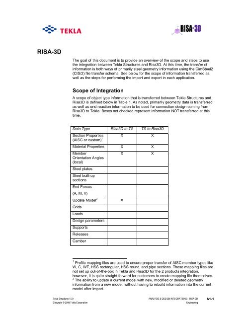
The goal of this document is to provide an overview of the scope and steps to use<br />
the integration between Tekla Structures and Risa<strong>3D</strong>. At this time, the transfer of<br />
information is both ways of primarily steel geometry information using the CimSteel2<br />
(CIS/2) file transfer schema. See below for the scope of information transferred as<br />
well as the steps for performing the import and export in each application.<br />
Scope of Integration<br />
A scope of object type information that is transferred between Tekla Structures and<br />
Risa<strong>3D</strong> is defined below in Table 1. As noted, primarily geometry data is transferred<br />
as well as end reaction information to be used for connection design coming from<br />
Risa<strong>3D</strong> to Tekla. Boxes not checked represent information NOT transferred at this<br />
time.<br />
Data Type Risa<strong>3D</strong> to TS TS to Risa<strong>3D</strong><br />
Section Properties X X<br />
(AISC or custom) 1<br />
Material Properties X X<br />
Member<br />
Orientation Angles<br />
(local)<br />
Steel plates<br />
Steel built-up<br />
sections<br />
End Forces<br />
(A, M, V)<br />
Update Model 2<br />
Grids<br />
Loads<br />
Design parameters<br />
Supports<br />
Releases<br />
Camber<br />
X<br />
X<br />
X<br />
1 Profile mapping files are used to ensure proper transfer of AISC member types like<br />
W, C, WT, HSS rectangular, HSS round, and pipe sections. These mapping files are<br />
not set up out-of-the-box in Tekla and Risa<strong>3D</strong> for the 2 products integration,<br />
however, it is quite straight forward for customers to create mapping file themselves.<br />
2 The ability to update a current model with new, modified or deleted geometry<br />
information from a new model, without having to rebuild information into the current<br />
model after import.<br />
Tekla Structures 15.0 ANALYSIS & DESIGN INTEGRATIONS : <strong>RISA</strong>-<strong>3D</strong> A1-1<br />
Copyright © 2008 Tekla Corporation<br />
Engineering
Table 1: Scope of Data in Tekla Structures – Risa<strong>3D</strong> Interoperability (CIS/2)<br />
How to Export from Risa<strong>3D</strong> to Tekla Structures<br />
A workflow is supported where the design engineer wishes to transfer their<br />
completed analytical model to Tekla Structures. With the model objects created<br />
natively in Tekla Structures, the user can create or modify their design drawings,<br />
coordinate with other design disciplines using various import/export formats,<br />
performing connection design and share their design model with the steel detailer.<br />
Some overall steps are defined below to export a CIS/2 file from Risa<strong>3D</strong>. Also read<br />
the provided Risa<strong>3D</strong> CIS2 Translator help documentation provided with the Risa<strong>3D</strong><br />
translator installation.<br />
1) Setup in Risa<strong>3D</strong> before Export:<br />
The beam offsets should be defined in the Risa<strong>3D</strong> model within the Member<br />
properties by changing the cardinal Point values to "8 Top – Center" as shown.<br />
That way the Position setting in the Tekla beam objects will be automatically set as<br />
Behind as desired.<br />
Figure 1a: Defining Member Offsets in Risa<strong>3D</strong> Model (Method 1)<br />
Figure 1b: Defining Member Offsets in Risa<strong>3D</strong> Model (Method 2)<br />
2) Using the Risa CIS/2 Translator<br />
Risa <strong>Technologies</strong> has a separate CIS/2 Module that is free to download off their<br />
website (http://www.risatech.com/products.asp) which also has documentation<br />
explaining the required setup and steps for exporting a CIS/2 model to Tekla. A<br />
couple of hints in using this tool in conjunction with Tekla Structures are defined<br />
here:<br />
A1-2 ANALYSIS & DESIGN INTEGRATIONS : <strong>RISA</strong>-<strong>3D</strong> Tekla Structures 15.0<br />
Engineering<br />
Copyright © 2008 Tekla Corporation
* Tekla prefers to receive a CIS/2 analysis model from Risa. Do not export a design<br />
model.<br />
* Mapping files for section shapes and material properties may be needed to be set<br />
up on either the export from Risa<strong>3D</strong> or the import into Tekla Structures.<br />
* Use the Cardinal Point export option to utilize the cardinal point definitions<br />
descrbed above for beam elements.<br />
Figure 2: Risa<strong>3D</strong> CIS/2 Translator – Export<br />
3) Import to Tekla Structures<br />
Once the CIS/2 file is created (with a suffix of *.stp), the file can be imported into<br />
Tekla Structures. The steps for importing the CIS/2 file are shown in Figure 3 and<br />
outlined here:<br />
Step 1: File/Import/CimSteel<br />
Step 2: Select New model. Give the import file a name<br />
Step 3: With the import parameters box open, go to the Filename box and search for<br />
the file. Note that the filepath length should be verified such that the entire stp file<br />
path fits in the filepath.<br />
Step 4: Select OK. The model should import<br />
Step 5: Once the model is imported, go to the View Properties and change the View<br />
Depth to be large enough to include the model. Also right click on the View and<br />
select Fit by Parts.<br />
Tekla Structures 15.0 ANALYSIS & DESIGN INTEGRATIONS : <strong>RISA</strong>-<strong>3D</strong> A1-3<br />
Copyright © 2008 Tekla Corporation<br />
Engineering
One thing to check if you ever get CIS2 files from customers and they aren't<br />
importing. Look at the heading of the CIS2 file and see if it says which Logic Product<br />
Model it is. If it's anything other then LPM6 (most likely you might see 5) I don't think<br />
we can import it. There is an LPM5 or LPM6 option on our export but not on our<br />
import. If customers have old analysis & design applications and haven't upgraded<br />
they might be sending you old file formats. Also, some CIS21 files come across,<br />
which are not valid.<br />
Figure 3: Tekla CIS/2 Import Interface<br />
How to Export from Tekla Structures to Risa<strong>3D</strong><br />
A workflow is supported where the design engineer wishes to transfer their initial<br />
design model in Tekla Structures and export it to Risa<strong>3D</strong>. Some overall steps are<br />
defined below in exporting a CIS/2 file from Tekla Structures. Also read the provided<br />
Risa<strong>3D</strong> CIS2 Translator help documentation provided with the Risa<strong>3D</strong> translator<br />
installation for importing the file into Risa<strong>3D</strong>.<br />
Tekla CIS/2 Export:<br />
Below is a step by step guide in exporting a CIS2 analysis model from Tekla<br />
Structures.<br />
Step 1 - Open the model in Tekla Structures that you want to export, and open a<br />
view showing the parts you would like to export. Make sure to load the View settings<br />
for exporting via CIS2.<br />
Step 2 – Make sure the Select Objects in Components icon is selected. 3 . If no<br />
connections are to be included in this export, only select the parts icon as well.<br />
Step 3 – Select entire model.<br />
3 If the Select Components or the Select Assembly icons are selected instead, the parts<br />
themselves will not export, even though they show up as selected in the view.<br />
A1-4 ANALYSIS & DESIGN INTEGRATIONS : <strong>RISA</strong>-<strong>3D</strong> Tekla Structures 15.0<br />
Engineering<br />
Copyright © 2008 Tekla Corporation
Step 4: File/Export/CimSteel/Analysis<br />
Step 5: Type in name of file ending in .stp.<br />
Figure 4: Tekla Structures CIS/2 Export<br />
Note that once the user sets up their standard settings, they should save away an<br />
attribute setting in the upper right corner of the dialog box. This value can be used<br />
in the future by loading it from the Load icon.<br />
Step 6: With settings defined, select Apply, select Create. The CIS2 model will run.<br />
A DOS window may appear in the background. That is a normal routine in the<br />
export. A note should appear in the lower left corner of the TS window that states<br />
"parts were successfully."<br />
Risa<strong>3D</strong> Import:<br />
Again using the CIS/2 Translator of Risa<strong>3D</strong>, the user specifies a .stp file created<br />
from Tekla and imports it as an analysis model into Risa<strong>3D</strong>. See Figure below for<br />
the interface of the Risa<strong>3D</strong> CIS/2 Translator.<br />
For the steps to set up and import a CIS/2 file, see the CIS/2 Translator<br />
documentation provided by Risa<strong>3D</strong>.<br />
Tekla Structures 15.0 ANALYSIS & DESIGN INTEGRATIONS : <strong>RISA</strong>-<strong>3D</strong> A1-5<br />
Copyright © 2008 Tekla Corporation<br />
Engineering
Figure 5: Risa<strong>3D</strong> CIS/2 Translator – Import<br />
Updating a Tekla Structures Model<br />
It is possible to receive updated models from Risa<strong>3D</strong> and merge those changes into<br />
your current Tekla model. Below are the steps and scope of how that process works.<br />
Step 1: Import first model as defined in previous steps. Choose to save the model<br />
for future imports as requested.<br />
Step 2: Import second model that is modified in Risa<strong>3D</strong>. This model will have its own<br />
import model name.<br />
Step 3: A change management dialog box will show up as shown stating what<br />
objects are added (green), modified (yellow) or deleted (red). Note that this change<br />
management of modified members is of section size, not moved or stretched<br />
members coming from Risa<strong>3D</strong>.<br />
A1-6 ANALYSIS & DESIGN INTEGRATIONS : <strong>RISA</strong>-<strong>3D</strong> Tekla Structures 15.0<br />
Engineering<br />
Copyright © 2008 Tekla Corporation
Setting up Mapping Files<br />
Setting up mapping files in Tekla Structures is as simple as editing a 2 column text<br />
file suffixed as a *.cnv file. Editing these files is described further in the Tekla Help<br />
section of Tekla Structures. Some example cnv files are located in each Tekla<br />
environment folder. Here is folder containing several cnv mapping files for the US<br />
market.<br />
C:\TeklaStructures\13.1\environments\usimp\profil<br />
The prfexp_* files are section property mapping files while the matexp_* files are<br />
material property mapping files.<br />
Risa<strong>3D</strong> also as the ability to define XML mapping files to use within their CIS/2<br />
Translator. See the Risa<strong>3D</strong> CIS/2 Translator documentation for more information.<br />
Tekla Structures 15.0 ANALYSIS & DESIGN INTEGRATIONS : <strong>RISA</strong>-<strong>3D</strong> A1-7<br />
Copyright © 2008 Tekla Corporation<br />
Engineering