Moeller Wiring Manual 02/05 - Klockner Moeller Parts
Moeller Wiring Manual 02/05 - Klockner Moeller Parts
Moeller Wiring Manual 02/05 - Klockner Moeller Parts

You also want an ePaper? Increase the reach of your titles
YUMPU automatically turns print PDFs into web optimized ePapers that Google loves.
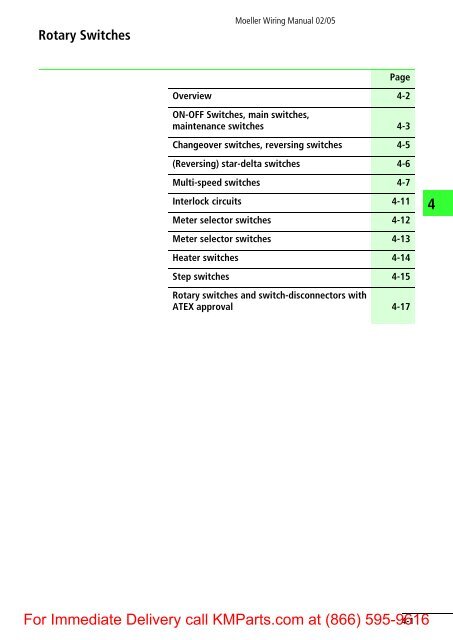
Rotary Switches<br />
<strong>Moeller</strong> <strong>Wiring</strong> <strong>Manual</strong> <strong>02</strong>/<strong>05</strong><br />
For Immediate Delivery call KM<strong>Parts</strong>.com at (866) 595-9616<br />
4-1<br />
Page<br />
Overview 4-2<br />
ON-OFF Switches, main switches,<br />
maintenance switches 4-3<br />
Changeover switches, reversing switches 4-5<br />
(Reversing) star-delta switches 4-6<br />
Multi-speed switches 4-7<br />
Interlock circuits 4-11<br />
Meter selector switches 4-12<br />
Meter selector switches 4-13<br />
Heater switches 4-14<br />
Step switches 4-15<br />
Rotary switches and switch-disconnectors with<br />
ATEX approval 4-17<br />
4
4<br />
Rotary Switches<br />
Overview<br />
Use and mounting forms<br />
<strong>Moeller</strong> rotary switches and switch-disconnectors<br />
are used as:<br />
a Main switches, main switches used as<br />
Emergency-Stop devices,<br />
b ON-OFF switches,<br />
c Safety switches,<br />
d Changeover switches,<br />
e Reversing switches, star-delta switches,<br />
multi-speed switches,<br />
f Step switches, control switches, coding<br />
switches, meter selector switches.<br />
<strong>Moeller</strong> <strong>Wiring</strong> <strong>Manual</strong> <strong>02</strong>/<strong>05</strong><br />
The following mounting forms are available:<br />
g Flush mounting,<br />
h Centre mounting,<br />
i Surface mounting,<br />
j Service distribution board mounting,<br />
k Rear mounting.<br />
Refer to the latest issue of our Main Catalogue for<br />
“Industrial Switchgear”.<br />
Other contact arrangements are listed in the K115<br />
specialist catalog in addition to the switches listed<br />
in the Main Catalogue.<br />
Basic P Iu Use as Mounting type<br />
type<br />
[KW] [A] a b c d e f g h i j k<br />
TM 3.0 10 – x – x – x k k – k –<br />
T0 6.5 20 x x – x x x + k k k +<br />
T3 13 32 x x – x x – + k k k +<br />
T5b 22 63 x x x x x – + – k – +<br />
T5 30 100 x – x x – – + – k – +<br />
T6 55 160 x – – x – – – – + – +<br />
T8 132 3151) x – – x – – – – + – +<br />
P1-25 13 25 x x x – – – + k + k +<br />
P1-32 15 32 x x x – – – + k + k +<br />
P3-63 37 63 x x x – – – + – + k +<br />
P3-100 50 100 x x x – – – + – + k +<br />
P5-125 45 125 x x – – – – + – – – +<br />
P5-160 55 160 x x – – – – + – – – +<br />
P5-250 90 250 x x – – – – + – – – +<br />
P5-315 110 315 x x – – – – + – – – +<br />
P = Max. motor rating; 400/415 V; AC-23 A<br />
Iu = Max. rated uninterrupted current<br />
1) In enclosed version (surface mounting), max. 275 A.<br />
kDepending on the number of contact units, function and contact sequence.<br />
+ Irrespective of the number of contact units, function and contact sequence.<br />
For 4-2Immediate<br />
Delivery call KM<strong>Parts</strong>.com at (866) 595-9616
<strong>Moeller</strong> <strong>Wiring</strong> <strong>Manual</strong> <strong>02</strong>/<strong>05</strong><br />
Rotary Switches<br />
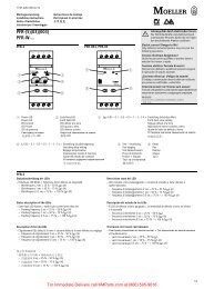
ON-OFF Switches, Main Switches, Maintenance Switches<br />
ON-OFF switches, main switches<br />
T0-2-1<br />
P1-25<br />
P1-32<br />
P3-63<br />
P3-100<br />
P5-125<br />
P5-160<br />
P5-250<br />
P5-315<br />
OFF<br />
ON<br />
FS 908<br />
Maintenance switches (safety switches)<br />
with auxiliary contacts<br />
T0-3-15680<br />
OFF<br />
ON<br />
FS 908<br />
P1-25/.../<br />
P1-32/.../<br />
P3-63/.../<br />
P3-100/.../<br />
...N/NHI11<br />
OFF<br />
ON<br />
L1<br />
L2<br />
L3<br />
L1<br />
L2<br />
L3<br />
N<br />
L1<br />
L2<br />
L3<br />
N<br />
FS 908<br />
1) Load shedding contact<br />
N<br />
N<br />
1<br />
2<br />
3<br />
4<br />
5<br />
6<br />
1<br />
2<br />
3<br />
4<br />
5<br />
6<br />
7<br />
8<br />
9<br />
10<br />
11<br />
12<br />
1<br />
2<br />
3<br />
4<br />
5<br />
6<br />
N<br />
N<br />
13<br />
14<br />
21<br />
22<br />
0 1<br />
0 1<br />
0 1<br />
1)<br />
1)<br />
These switches can also be used as<br />
switch-disconnectors for lighting, heating or<br />
combined loads.<br />
Main switches to IEC/EN 60 204 for rear mounting<br />
switches with door interlock, padlocking feature,<br />
finger-proof incoming terminals, N and PE<br />
terminal, red thumb-grip handle (black, if<br />
required), warning label.<br />
If it is not clear which drive is associated with<br />
which main switch, an additional maintenance<br />
switch is required close to each drive.<br />
Maintenance switches are fitted to electrical<br />
machines or installations to provide safe working<br />
conditions in accordance with the safety<br />
regulations.<br />
By attaching his own padlock to the SVB<br />
padlocking feature, the electrician can protect<br />
himself against anyone switching on without<br />
authorization (a section “Circuit diagram<br />
example for maintenance switches with a load<br />
shedding contact and (or) switch position<br />
indicator”, page 4-4).<br />
For Immediate Delivery call KM<strong>Parts</strong>.com at (866) 595-9616<br />
4-3<br />
4
4<br />
<strong>Moeller</strong> <strong>Wiring</strong> <strong>Manual</strong> <strong>02</strong>/<strong>05</strong><br />
Rotary Switches<br />
ON-OFF Switches, Main Switches, Maintenance Switches<br />
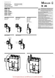
Circuit diagram example for maintenance<br />
switches with a load shedding contact and<br />
(or) switch position indicator<br />
L1<br />
L2<br />
L3<br />
N<br />
Q11<br />
Q1<br />
F1<br />
P1: On<br />
P2: Off<br />
Q11: Load shedding<br />
T0(3)-3-15683 circuit diagram<br />
1-2,3-4,5-6<br />
7-8,11-12<br />
9-10<br />
F2<br />
1<br />
2<br />
3<br />
4<br />
5<br />
6<br />
1 3 5<br />
2 4 6<br />
U V W<br />
M<br />
3<br />
7 9 11<br />
8 10 12<br />
P1 P2<br />
F0<br />
F2<br />
O<br />
I<br />
Q11<br />
T0(3)-3-15683 maintenance switch<br />
13<br />
Q11<br />
Function<br />
Load shedding: When<br />
switching on, the main<br />
current contacts close first,<br />
then the contactor is<br />
activated via the late-make<br />
N/O contact. When<br />
switching off, the contactor<br />
is first disconnected by<br />
opening of the early-break<br />
contact, then the main<br />
contacts isolate the motor<br />
supply.<br />
Switch position<br />
indication: The position of<br />
the switch can be signalled<br />
to the control panel or<br />
mimic diagram panel via<br />
additional NO and NC<br />
contacts.<br />
For 4-4Immediate<br />
Delivery call KM<strong>Parts</strong>.com at (866) 595-9616<br />
95<br />
96<br />
21<br />
22<br />
14<br />
A1<br />
A2<br />
13<br />
14
Rotary Switches<br />
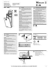
Changeover Switches, Reversing Switches<br />
Changeover switches<br />
T0-3-8212<br />
T3-3-8212<br />
T5B-3-8212<br />
T5-3-8212<br />
T6-3-8212<br />
T8-3-8212<br />
0<br />
1 2<br />
FS 684<br />
Reversing switches<br />
T0-3-8401<br />
T3-3-8401<br />
T5B-3-8401<br />
T5-3-8401<br />
0<br />
1 2<br />
FS 684<br />
<strong>Moeller</strong> <strong>Wiring</strong> <strong>Manual</strong> <strong>02</strong>/<strong>05</strong><br />
L1 L2 L3<br />
L1 L2 L3<br />
1<br />
2<br />
3<br />
4<br />
5<br />
6<br />
7<br />
8<br />
9<br />
10<br />
For Immediate Delivery call KM<strong>Parts</strong>.com at (866) 595-9616<br />
4-5<br />
1<br />
2<br />
3<br />
4<br />
5<br />
6<br />
7<br />
8<br />
9<br />
10<br />
11<br />
12<br />
1<strong>02</strong><br />
1 0 2<br />
4
4<br />
Rotary Switches<br />
(Reversing) Star-Delta Switches<br />
Star-delta switches<br />
T0-4-8410<br />
T3-4-8410<br />
Y<br />
0<br />
FS 635<br />
T5B-4-8410<br />
T5-4-8410<br />
Reversing star-delta switches<br />
T0-6-15877<br />
T3-6-15877<br />
0<br />
Y Y<br />
FS 638<br />
<strong>Moeller</strong> <strong>Wiring</strong> <strong>Manual</strong> <strong>02</strong>/<strong>05</strong><br />
L1 L2 L3<br />
For 4-6Immediate<br />
Delivery call KM<strong>Parts</strong>.com at (866) 595-9616<br />
W1<br />
W2<br />
W2<br />
W1<br />
V2<br />
V2<br />
U1<br />
U2<br />
V1<br />
L1L2L3<br />
U1<br />
U2<br />
V1<br />
1<br />
2<br />
3<br />
4<br />
5<br />
6<br />
7<br />
8<br />
9<br />
10<br />
11<br />
12<br />
13<br />
14<br />
15<br />
16<br />
1<br />
SOND 28 ) 2<br />
3<br />
4<br />
5<br />
6<br />
7<br />
8<br />
9<br />
10<br />
11<br />
12<br />
13<br />
14<br />
15<br />
16<br />
17<br />
18<br />
19<br />
20<br />
21<br />
22<br />
23<br />
24<br />
1<br />
0YΔ<br />
Y 0 Y<br />
1) Standard contactor interlock<br />
a section “Interlock Circuits”, page 4-11
Rotary Switches<br />
Multi-Speed Switches<br />
2 speeds, non-reversing<br />
Tapped winding arrangement<br />
T0-4-8440<br />
T3-4-8440<br />
T5B-4-8440<br />
T5-4-8440<br />
1<br />
0 2<br />
FS 644<br />
2 separate windings<br />
T0-3-8451<br />
T3-3-8451<br />
T5B-3-8451<br />
T5-3-8451<br />
1<br />
0 2<br />
FS 644<br />
<strong>Moeller</strong> <strong>Wiring</strong> <strong>Manual</strong> <strong>02</strong>/<strong>05</strong><br />
L1L2L3<br />
1U<br />
2W 2V<br />
2U<br />
1W 1V<br />
�<br />
a without links<br />
For Immediate Delivery call KM<strong>Parts</strong>.com at (866) 595-9616<br />
4-7<br />
1U<br />
1W 1V<br />
L1L2L3<br />
2U<br />
1<br />
2<br />
3<br />
4<br />
5<br />
6<br />
7<br />
8<br />
9<br />
10<br />
11<br />
12<br />
13<br />
14<br />
15<br />
16<br />
2W 2V<br />
0 1 2<br />
1<br />
2<br />
3<br />
4<br />
5<br />
6<br />
7<br />
8<br />
9<br />
10<br />
11<br />
12<br />
0 12<br />
4
4<br />
Rotary Switches<br />
Multi-Speed Switches<br />
2 speeds, reversing<br />
Tapped winding arrangement<br />
T0-6-15866<br />
T3-6-15866<br />
0<br />
1 1<br />
2 2<br />
FS 629<br />
T5B-7-15866<br />
T5-7-15866<br />
1 0 1<br />
2 2<br />
FS 441<br />
2 separate windings, reversing<br />
T0-5-8453<br />
T3-5-8453<br />
0<br />
1 1<br />
2 2<br />
FS 629<br />
<strong>Moeller</strong> <strong>Wiring</strong> <strong>Manual</strong> <strong>02</strong>/<strong>05</strong><br />
L1L2 L3<br />
1U<br />
1<br />
2<br />
3<br />
4<br />
5<br />
6<br />
7<br />
8<br />
9<br />
10<br />
11<br />
12<br />
13<br />
14<br />
15<br />
16<br />
17<br />
18<br />
19<br />
20<br />
21<br />
2W 2V 22<br />
23<br />
2U 24<br />
1W 1V<br />
2 1 0 1 2<br />
For 4-8Immediate<br />
Delivery call KM<strong>Parts</strong>.com at (866) 595-9616<br />
1U<br />
1W 1V<br />
L1L2L3<br />
2U<br />
2W 2V<br />
1<br />
2<br />
3<br />
4<br />
5<br />
6<br />
7<br />
8<br />
9<br />
10<br />
11<br />
12<br />
13<br />
14<br />
15<br />
16<br />
17<br />
18<br />
19<br />
20<br />
2 1 0 1 2
Rotary Switches<br />
Multi-Speed Switches<br />
3 speeds, non-reversing<br />
Tapped winding arrangement, single<br />
winding for low speed<br />
T0-6-8455<br />
T3-6-8455<br />
T5B-6-8455<br />
T5-6-8455<br />
1 2<br />
0 3<br />
FS 616<br />
<strong>Moeller</strong> <strong>Wiring</strong> <strong>Manual</strong> <strong>02</strong>/<strong>05</strong><br />
L1 L2 L3<br />
0-(A)y- (B)d = (B)y y<br />
0 123<br />
For Immediate Delivery call KM<strong>Parts</strong>.com at (866) 595-9616<br />
4-9<br />
1U<br />
1W 1V<br />
1U<br />
2W 2V<br />
A B<br />
2U<br />
1W 1V<br />
1<br />
2<br />
3<br />
4<br />
5<br />
6<br />
7<br />
8<br />
9<br />
10<br />
11<br />
12<br />
13<br />
14<br />
15<br />
16<br />
17<br />
18<br />
19<br />
20<br />
21<br />
22<br />
23<br />
24<br />
4
4<br />
Rotary Switches<br />
Multi-Speed Switches<br />
3 speeds, non-reversing<br />
Tapped winding arrangement, single<br />
winding for high speed<br />
T0-6-8459<br />
T3-6-8459<br />
1 2<br />
0 3<br />
FS 616<br />
T5B-6-8459<br />
T5-6-8459<br />
1<br />
0<br />
2<br />
3<br />
FS 420<br />
<strong>Moeller</strong> <strong>Wiring</strong> <strong>Manual</strong> <strong>02</strong>/<strong>05</strong><br />
L1 L2 L3<br />
0-(B)d- (B)y y -(A)y<br />
0 123<br />
For 4-10Immediate<br />
Delivery call KM<strong>Parts</strong>.com at (866) 595-9616<br />
1U<br />
1W 1V<br />
1U<br />
2W 2V<br />
A B<br />
2U<br />
1W 1V<br />
1<br />
2<br />
3<br />
4<br />
5<br />
6<br />
7<br />
8<br />
9<br />
10<br />
11<br />
12<br />
13<br />
14<br />
15<br />
16<br />
17<br />
18<br />
19<br />
20<br />
21<br />
22<br />
23<br />
24
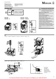
Rotary Switches<br />
Interlock Circuits<br />
Interlock circuits between rotary switches and<br />
contactors with overload relays provide neat and<br />
economical solutions for many switching drive<br />
tasks.The following points are common to all<br />
interlock circuits:<br />
Without mains disconnection (SOND 27)<br />
Mains disconnection only by contactorprimarily<br />
for star-delta circuit<br />
Q11<br />
F0<br />
F2<br />
S0<br />
Q11<br />
Q11<br />
Interlock with contactor (SOND 29)<br />
Contactor can be energized only when switch is<br />
in the Off position<br />
Q11<br />
M<br />
3~<br />
M<br />
3~<br />
F0<br />
F2<br />
S0<br />
Q11<br />
Q11<br />
S1<br />
Q1<br />
012 Q1<br />
012 Control section<br />
SOND 27<br />
Power section<br />
without mains<br />
disconnection<br />
Circuit as required<br />
Control section<br />
SOND 29<br />
Power section<br />
Circuit as required<br />
<strong>Moeller</strong> <strong>Wiring</strong> <strong>Manual</strong> <strong>02</strong>/<strong>05</strong><br />
Protection against automatic restarting after a<br />
motor overload or power failure<br />
The facility for remote disconnection (e.g.<br />
emergency-stop) can be provided by one or<br />
more Off pushbuttons.<br />
With mains disconnection (SOND 28)<br />
Mains disconnection by contactor and switch<br />
Interlock with contactor (SOND 30)<br />
Contactor can be energized only when switch is<br />
in an operating position<br />
For Immediate Delivery call KM<strong>Parts</strong>.com at (866) 595-9616<br />
4-11<br />
Q11<br />
Q11<br />
M<br />
3~<br />
M<br />
3~<br />
F0<br />
F2<br />
S0<br />
Q11<br />
Q11<br />
F0<br />
F2<br />
S0<br />
S1<br />
Q11<br />
Q11<br />
Q1<br />
012 Q1<br />
012 Control section<br />
SOND 28<br />
Power section<br />
without mains<br />
disconnection<br />
Circuit as required<br />
Control section<br />
SOND 30<br />
Power section<br />
Circuit as required<br />
4
4<br />
Rotary Switches<br />
Single-Phase Starting Switches<br />
Meter selector switches enable you to measure<br />
currents, voltages and power in three-phase<br />
systems with only one measuring device.<br />
Voltmeter selector switches<br />
T0-3-8007<br />
3 x phase to phase<br />
3 x phase to neutral with “0” position<br />
0<br />
L1-L2 L1-N<br />
L2-L3 L2-N<br />
L3-L1 L3-N<br />
FS 1410759<br />
1<br />
2<br />
3<br />
4<br />
5<br />
6<br />
7<br />
8<br />
9<br />
10<br />
11<br />
12<br />
Ammeter selector switches<br />
T0-5-15925<br />
T3-5-15925<br />
For direct measurement<br />
V<br />
L3-L1<br />
L2-L3<br />
L1-L2<br />
0<br />
L1-N<br />
L2-N<br />
L3-N<br />
<strong>Moeller</strong> <strong>Wiring</strong> <strong>Manual</strong> <strong>02</strong>/<strong>05</strong><br />
L1L2L3 N L1-L2<br />
L2-L3<br />
L1L2 L3<br />
0<br />
L3 L1<br />
0 L1L2L3 0<br />
1<br />
L2<br />
FS 9440<br />
2<br />
3<br />
4<br />
5<br />
6<br />
7<br />
8<br />
9<br />
A<br />
10<br />
11<br />
12<br />
13<br />
14<br />
15<br />
16<br />
17<br />
18<br />
L1L2L3<br />
Numerous circuits are possible for the different<br />
measurements, some of the most common ones<br />
being shown below.<br />
T0-2-15922<br />
3 x phase to neutral without “0”<br />
position<br />
For 4-12Immediate<br />
Delivery call KM<strong>Parts</strong>.com at (866) 595-9616<br />
L3-L1<br />
FS 164854<br />
V<br />
L1L2L3<br />
1<br />
2<br />
3<br />
4<br />
5<br />
6<br />
7<br />
8<br />
L1-L2<br />
L2-L3<br />
L3-L1
Rotary Switches<br />
Meter Selector Switches<br />
Ammeter selector switches<br />
T0-3-8048<br />
T3-3-8048<br />
For measurement via transformers, complete rotation possible<br />
L3<br />
0<br />
L1<br />
L2<br />
FS 9440<br />
Wattmeter selector switches<br />
T0-5-8043<br />
T3-5-8043<br />
Two-phase method (Aron circuit) for three-cable<br />
installations loaded as required. The sum of the<br />
two readings gives the total output.<br />
0<br />
1 2<br />
FS 953<br />
<strong>Moeller</strong> <strong>Wiring</strong> <strong>Manual</strong> <strong>02</strong>/<strong>05</strong><br />
0 L1L2L3 0<br />
For Immediate Delivery call KM<strong>Parts</strong>.com at (866) 595-9616<br />
4-13<br />
L1<br />
L2<br />
L3<br />
A<br />
1<br />
2<br />
3<br />
4<br />
5<br />
6<br />
7<br />
8<br />
9<br />
10<br />
11<br />
12<br />
The Aron circuit will give a correct result for<br />
four-cable systems only when the sum of the<br />
currents equals zero, i.e. only when the four-cable<br />
system is balanced.<br />
L1<br />
L2<br />
L3<br />
W<br />
1 2 3 11<br />
1<br />
2<br />
3<br />
4<br />
5<br />
6<br />
7<br />
8<br />
9<br />
10<br />
11<br />
12<br />
13<br />
14<br />
15<br />
16<br />
17<br />
18<br />
1 0 2<br />
4
4<br />
Rotary Switches<br />
Heater Switches<br />
1-pole disconnection, 3 steps<br />
T0-2-8316<br />
T3-2-8316<br />
T5B-2-8316<br />
1<br />
0<br />
2<br />
3<br />
FS 420<br />
T0-2-15114, complete rotation possible<br />
1<br />
0 1+2<br />
2<br />
FS 193840<br />
L1 L2 L3<br />
<strong>Moeller</strong> <strong>Wiring</strong> <strong>Manual</strong> <strong>02</strong>/<strong>05</strong><br />
q switched<br />
Q not switched<br />
Further heater switches, 2- and 3-pole, with alternative<br />
circuitry, output stages, and number of steps are<br />
described in the <strong>Moeller</strong> Main Catalogue, Industrial<br />
Switchgear and in the catalogue K 115.<br />
For 4-14Immediate<br />
Delivery call KM<strong>Parts</strong>.com at (866) 595-9616<br />
I<br />
II<br />
III<br />
1<br />
2<br />
3<br />
4<br />
5<br />
6<br />
7<br />
8<br />
1<br />
2<br />
3<br />
4<br />
5<br />
6<br />
7<br />
8<br />
011+22 0<br />
0123<br />
1<br />
2<br />
3<br />
I II III
Rotary Switches<br />
Step Switches<br />
<strong>Moeller</strong> <strong>Wiring</strong> <strong>Manual</strong> <strong>02</strong>/<strong>05</strong><br />
One step closed in each position, complete rotation possible<br />
T0-6-8239<br />
T3-6-8239<br />
1 23 4 5 6<br />
7<br />
12 8<br />
1110<br />
9<br />
FS 301<br />
1 2 3 4<br />
For Immediate Delivery call KM<strong>Parts</strong>.com at (866) 595-9616<br />
4-15<br />
1<br />
2<br />
3<br />
4<br />
5<br />
6<br />
7<br />
8<br />
9<br />
10<br />
11<br />
12<br />
13<br />
14<br />
15<br />
16<br />
17<br />
18<br />
19<br />
20<br />
21<br />
22<br />
23<br />
24<br />
5 6 7 8 9 10 1112<br />
4
4<br />
Rotary Switches<br />
Step Switches<br />
Stay-put switches<br />
On-Off stay-put switches<br />
1-pole: T0-1-15401<br />
2-pole: T0-1-154<strong>02</strong><br />
3-pole: T0-2-15403<br />
0 1<br />
FS 415<br />
Changeover switches<br />
1-pole: T0-1-15421<br />
2-pole: T0-2-15422<br />
3-pole: T0-3-15423<br />
0<br />
2 1<br />
FS 429<br />
1<br />
2<br />
3<br />
4<br />
5<br />
6<br />
7<br />
8<br />
9<br />
10<br />
11<br />
12<br />
2 01<br />
<strong>Moeller</strong> <strong>Wiring</strong> <strong>Manual</strong> <strong>02</strong>/<strong>05</strong><br />
On-Off stay-put switches (also usable as main switches, mains isolating device)<br />
1-pole: T0-1-15521<br />
2-pole: T0-2-15522<br />
3-pole: T0-3-15523<br />
With pulsed contact in the intermediate position<br />
ON<br />
0 1<br />
OFF<br />
FS 908<br />
For 4-16Immediate<br />
Delivery call KM<strong>Parts</strong>.com at (866) 595-9616<br />
1<br />
2<br />
3<br />
4<br />
5<br />
6<br />
0 1<br />
1-pole: T0-1-15431<br />
2-pole: T0-2-15432<br />
3-pole: T0-3-15433<br />
0<br />
HAND AUTO<br />
FS 1401<br />
1<br />
2<br />
3<br />
4<br />
5<br />
6<br />
7<br />
8<br />
9<br />
10<br />
11<br />
12<br />
1<br />
2<br />
3<br />
4<br />
5<br />
6<br />
7<br />
8<br />
9<br />
10<br />
11<br />
12<br />
HAND 0 AUTO
<strong>Moeller</strong> <strong>Wiring</strong> <strong>Manual</strong> <strong>02</strong>/<strong>05</strong><br />
Rotary Switches<br />
Rotary Switches and Switch-Disconnectors with ATEX Approval<br />
What does ATEX stand for?<br />
ATmosphéres EXplosibles = ATEX<br />
For operators: 1999/92/EC<br />
(binding from 06/2006)<br />
Explosive atmospheres<br />
Gas Dust<br />
Explosion risk assessment<br />
Gas, steam, Dust Ex risk<br />
mist<br />
Zone 0 Zone 20 continuous, frequent, long,<br />
Zone 1 Zone 21 occasional<br />
Zone 2 Zone 22 normally not, but<br />
otherwise for a short<br />
period<br />
Selection of devices and protective<br />
systems by categories<br />
Gas, steam,<br />
mist Zone 0,<br />
1, 2 Zone 1, 2<br />
Zone 2<br />
Dust<br />
Zone 20, 21, 22<br />
Zone 21, 22<br />
Zone 22<br />
Category<br />
1<br />
1, 2<br />
1, 2, 3<br />
Two standards<br />
For manufacturers: 94/9/EC<br />
(binding from 06/2003)<br />
Device groups<br />
Group<br />
I<br />
II<br />
Application field<br />
Mining<br />
everything apart from<br />
mining<br />
Selection of devices by device<br />
groups<br />
Group<br />
I<br />
I<br />
II<br />
II<br />
II<br />
Category<br />
M1<br />
M2<br />
1<br />
2<br />
3<br />
Safety<br />
very high<br />
high<br />
very high<br />
high<br />
normal<br />
For Immediate Delivery call KM<strong>Parts</strong>.com at (866) 595-9616<br />
4-17<br />
4
4<br />
<strong>Moeller</strong> <strong>Wiring</strong> <strong>Manual</strong> <strong>02</strong>/<strong>05</strong><br />
Rotary Switches<br />
Rotary Switches and Switch-Disconnectors with ATEX Approval<br />
ATEX approval for <strong>Moeller</strong><br />
<strong>Moeller</strong> offers T rotary switches (from 32 to 100 A)<br />
and P switch-disconnectors (from 25 to 100 A) in<br />
accordance with the binding ATEX Directive<br />
94/6 EC (binding from 06/2006). The switches are<br />
provided with the equipment marking Ex II3D<br />
IP5X T90°C and are approved for the Ex zone 22<br />
in explosive dust atmospheres.<br />
Explosive dust atmospheres are present in:<br />
Mills,<br />
Metal polishing workshops,<br />
Woodworking facilities,<br />
Cement industry,<br />
Aluminium industry,<br />
Animal feed industry,<br />
Grain storage and preparation,<br />
Agriculture,<br />
Pharmacy etc.<br />
The ATEX switches are used as:<br />
Main switches<br />
Maintenance switches<br />
Repair switches,<br />
ON-OFF switches or,<br />
General installation and application notes<br />
Only suitable cable glands may be used for<br />
category 3D!<br />
Use only temperature resistant cables (> 90°C)!<br />
The maximum surface temperature is 90°C!<br />
Operation only permissible at an ambient<br />
temperature between –20 and +40°C!<br />
Observe the technical data of the switch used!<br />
Changeover switches.<br />
The following ATEX switches are available:<br />
Current<br />
range<br />
T rotary<br />
switches<br />
P<br />
switch-disconnectors<br />
25 A – P1-25/I2<br />
32 A T3-.../I2 P1-32/I2<br />
63 A T5B-.../I4 P3-63/I4<br />
100 A T5-.../I5 P3-100/I5<br />
Note<br />
<strong>Moeller</strong> ATEX switches have passed the EC<br />
prototype test for main, maintenance and repair<br />
switches for the current ranges from 25 to 100 A.<br />
They are approved for explosive dust atmospheres<br />
in accordance with category II 3D, with the test<br />
number: BVS 04E 106X.<br />
For further information see installation<br />
instructions AWA1150-2141.<br />
Never open the device in dust explosive<br />
atmospheres!<br />
Observe the requirements of EN 5<strong>02</strong>81-1-2!<br />
It should be checked that the device is free of<br />
dust prior to assembly!<br />
Do not open the device when energized!<br />
For 4-18Immediate<br />
Delivery call KM<strong>Parts</strong>.com at (866) 595-9616