E inglese_04.pdf - Fini compressors
E inglese_04.pdf - Fini compressors
E inglese_04.pdf - Fini compressors

You also want an ePaper? Increase the reach of your titles
YUMPU automatically turns print PDFs into web optimized ePapers that Google loves.
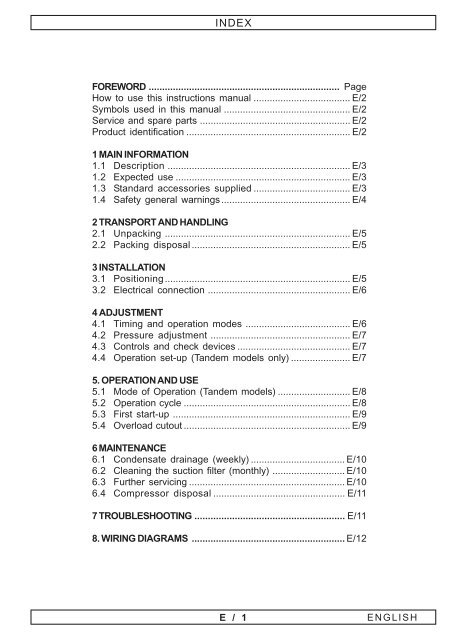
INDEX<br />
FOREWORD ....................................................................... Page<br />
How to use this instructions manual .................................... E/2<br />
Symbols used in this manual ............................................... E/2<br />
Service and spare parts ........................................................ E/2<br />
Product identification ............................................................. E/2<br />
1 MAIN INFORMATION<br />
1.1 Description .................................................................... E/3<br />
1.2 Expected use ................................................................. E/3<br />
1.3 Standard accessories supplied .................................... E/3<br />
1.4 Safety general warnings................................................ E/4<br />
2 TRANSPORT AND HANDLING<br />
2.1 Unpacking ..................................................................... E/5<br />
2.2 Packing disposal ........................................................... E/5<br />
3 INSTALLATION<br />
3.1 Positioning..................................................................... E/5<br />
3.2 Electrical connection ..................................................... E/6<br />
4 ADJUSTMENT<br />
4.1 Timing and operation modes ....................................... E/6<br />
4.2 Pressure adjustment .................................................... E/7<br />
4.3 Controls and check devices .......................................... E/7<br />
4.4 Operation set-up (Tandem models only) ...................... E/7<br />
5. OPERATION AND USE<br />
5.1 Mode of Operation (Tandem models) ........................... E/8<br />
5.2 Operation cycle .............................................................. E/8<br />
5.3 First start-up .................................................................. E/9<br />
5.4 Overload cutout .............................................................. E/9<br />
6 MAINTENANCE<br />
6.1 Condensate drainage (weekly) ................................... E/10<br />
6.2 Cleaning the suction filter (monthly) ........................... E/10<br />
6.3 Further servicing .......................................................... E/10<br />
6.4 Compressor disposal ................................................. E/11<br />
7 TROUBLESHOOTING ........................................................ E/11<br />
8. WIRING DIAGRAMS ......................................................... E/12<br />
E / 1<br />
ENGLISH
FOREWORD<br />
How to use this instructions manual<br />
This manual is an integral part of your compressor, and shall be kept with it for future<br />
reference.<br />
Retain this manual in a suitable place and when consulting it, take care of not spoiling it.<br />
Should your compressor be resold, entrust it to the new owner who will obviously need<br />
the information contained.<br />
Before starting the compressor read this manual carefully so as to understand the contents<br />
clearly; consult it whenever any doubt arise.<br />
This manual contains information useful for your safety. Follow the indications contained<br />
in it and perform the recommended procedures which, if not properly observed, could<br />
result in damage to equipment or could cause personal injury.<br />
Moreover, you will find useful information which will make the use and maintenance of<br />
your compressor easier.<br />
Should the manual be lost, ask for a new copy.<br />
This manual does not include the spare parts list, which is available by our Authorized<br />
Resellers.<br />
Symbols used in this manual<br />
In order to make evident same special information, the following symbols are used:<br />
WARNING<br />
It refers to safety instructions to be complied with in order to ensure maximum safety<br />
conditions to the operator as well as to people in the working area.<br />
NOTE<br />
Recommended instructions or precautionary measures to facilitate maintenance<br />
operations or to clarify special operations.<br />
SPECIALIZED PERSONNEL<br />
Symbols indicating operations to be carried out by specialized personnel only.<br />
Service and Spare Parts<br />
In case of replacement of any part of your compressor, use only ORIGINAL SPARE PARTS.<br />
Contact any Authorized Service Centre which, having its own stock, will supply you at its<br />
best. Imitation spare parts hide potential risks including the risk of injuries to people. In<br />
order to grant you efficient service or to remove any doubt, when asking for information<br />
always quote model, type and serial number of your compressor, which are printed on<br />
the cover of this manual and on the compressor's nameplate.<br />
Product identification<br />
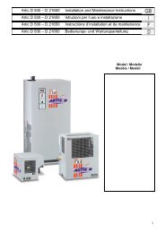
The compressor Your have purchased has its own CE<br />
plate showing the following data:<br />
1) Manufacturer’s data<br />
2) CE mark – year of manufacture<br />
3) TYPE = name of the compressor<br />
CODE = compressor code<br />
SERIAL NO. = serial number of the compressor You<br />
have purchased (to be always mentioned when calling for technical assistance)<br />
4) air delivered by the compressor expressed in (l/min) and (cfm)<br />
5) max. operating pressure (bar and PSI) – compressor noise level in dB(A)<br />
6) electric data: voltage (V/ph), frequency (Hz), absorption (A) - power (HP and kW), rotations<br />
per minute (Rpm).<br />
7) other approvals<br />
E / 2
1.MAIN INFORMATION<br />
1.1 Description<br />
• Our OILLESS series includes the <strong>compressors</strong> mod. MEDICAIR, that is <strong>compressors</strong><br />
which do not need any lubricants to run. Such peculiarity ensures a very easy use and<br />
reduced ordinary service. Moreover, such feature allows working even on inclined plane<br />
without jeopardizing the proper operation of the machine.<br />
The range of the models includes versions with drier and soundproof cabin.<br />
• The main components of your compressor are shown in the information table enclosed<br />
to this instruction manual. Such table includes the max. overall dimensions of the<br />
compressor, and the main spare and wear parts.<br />
Among the most important features, the following should be noted:<br />
• inner tank walls coated with rustproof paint,<br />
• inner rings made of special friction-free material,<br />
• aluminium piston coated with special friction-free material,<br />
• absorption drier with cleaning automatic cycle,<br />
• ergonomic guards with anti-shock handle,<br />
• pressure switch / remote pressure switch with integrated starter/stop switch,<br />
• non-return and safety valves,<br />
• overload cutout and cooling fan,<br />
• cock for condensate drainage,<br />
• single- and three-phase motors, 230 and 400 V.<br />
1.2 Expected use<br />
• Your compressor was thought, manufactured and arranged for being used as a<br />
compressed air source solely, according to the safety instructions described hereunder.<br />
• Several pneumatic accessories can be connected to your compressor. For a<br />
proper use, refer to their single user’s manual.<br />
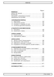
1.3 Standard Accessories Supplied (Fig. 1)<br />
• Manual for Use and Maintenance<br />
• Vibration-damping Pad<br />
• Technical Data Sheet (size and weight).<br />
1<br />
x 4<br />
E / 3<br />
ENGLISH
1.MAIN INFORMATION<br />
1.4 Safety general warnings<br />
Before operating your compressor read this Manual very carefully.<br />
Your compressor was thought, manufactured and arranged for the operations depicted<br />
below. Any other use is not allowed.<br />
The MANUFACTURER assumes no responsibility for any damages resulting from<br />
improper use o for not compliance with the instructions described in this manual.<br />
WHAT YOU MUST DO:<br />
Learn how to use all controls and how to stop the compressor suddenly.<br />
Before carrying out any service or routine operation to your compressor, ensure the<br />
power has been cut off and all pressure has been released from the tank, so as to<br />
prevent any sudden unexpected re-start.<br />
After any maintenance operation, make sure all components have been fitted correctly.<br />
Before switching on the compressor, in order to ensure working safety, always follow the<br />
recommended procedures described in the § Installation.<br />
Keep out children or animals from the operating area so as to prevent damages or<br />
injuries caused by any accessory connected to your compressor.<br />
Read carefully the instructions regarding the accessory fitted; moreover, if you mount the<br />
spray gun, ensure that the area is provided with proper air change system.<br />
An operator working close to the compressor should wear ear protection devices.<br />
Provide for protection against accidental contacts by automatic power cut off, taking into<br />
consideration that the compressor is of class I and is equipped with connection to the<br />
earth.<br />
WHAT YOU MUST NOT DO:<br />
Do not spray in closed areas or near naked flames.<br />
Do not touch the cylinder heads, the cooling fins, and the feed pipe. During operation,<br />
because of the high temperature achieved, those parts keep hot for a certain time even<br />
after switching off the compressor.<br />
Do not leave inflammable, nylon objects, or cloths near the compressor.<br />
Do not move the compressor with the tank under pressure.<br />
Do not use the compressor with the supply cord damaged or with precarious electric<br />
connection.<br />
Do not direct the air jet towards people or animals.<br />
Do not allow anyone to operate the compressor unless he/she has received correct<br />
instructions.<br />
Do not hit the flywheel and the fans with metallic or sharp objects as they could break<br />
during operation.<br />
Do not operate the compressor without air filter.<br />
Do not carry out any repair or adjustment operations on safety valve and tank.<br />
Do not use the compressor in a potential explosive environment.<br />
Do not connect a hose which has a flow rate lower than that of the compressor to the air<br />
outlet cock.<br />
Do not use the compressor at temperatures lower than O°C (temp. range: +5°C / +45°C).<br />
E / 4
2.TRANSPORT AND HANDLING<br />
2.1 Compressor unpacking and handling (Fig. 2)<br />
Make sure both the machine and all supplied<br />
accessories are perfectly safe and undamaged.<br />
When delivered, the machine is on a wooden pallet and<br />
protected by a top cardboard packing. Wear safety gloves<br />
and cut the outer straps and withdraw the cardboard<br />
from the top, then unscrew the nuts which lock the<br />
compressor.<br />
Warning: <strong>compressors</strong> equipped with drier tend to bend<br />
because of the weight on the rear side. Balance the unit<br />
before lifting it.<br />
• Compressor with 24-litre tank: size the compressor by<br />
the handles with the help of another person, then lift it.<br />
• Compressor with tank over 24 litres: Lift the<br />
compressor with a fork truck of suitable capacity (see<br />
the information table), by fitting the forks through the tank<br />
supporting feet and fitting a wooden bar perpendicular<br />
so as to prevent the compressor from shifting during<br />
lifting.<br />
Fit anti-vibrating elements<br />
2.2 Packing disposal<br />
Save the packing material in case you ever need to<br />
transport the compressor in the future.<br />
We recommend that you store the packing in a safe<br />
location, at least within the period of the guarantee. In<br />
case of need, it will be easier to send the compressor to<br />
the service centre.<br />
Afterwards, put it into the care of the company or board<br />
in charge of elimination.<br />
2<br />
3. INSTALLATION<br />
3.1 Positioning<br />
As previously said all <strong>compressors</strong> can work properly even on an plane with a transversal<br />
or longitudinal inclination over 15°.<br />
In order to ensure proper air flow, position and fit the compressor so as to leave the<br />
ventilation grill at least at 20 cm from any obstacles which may prevent air from flowing<br />
out correctly, and so as to facilitate maintenance and cleaning operations.<br />
When choosing the room of installation of your compressor, make sure that the installation<br />
place meets all the safety standards in force in the country in which the compressor is<br />
used, and that the following conditions are respected:<br />
• low room dust percentage,<br />
• the working room should be large enough to allow the room temperature to be kept<br />
within 40° when the machine is running.<br />
If the above requirement cannot be met, fit one or more exhausters for the hot air.<br />
Fit the highest number possible for the working room.<br />
E / 5<br />
ENGLISH
3. INSTALLATION<br />
3.2 Electric connection<br />
All <strong>compressors</strong> are delivered only after a successful<br />
testing period at the factory and are ready to use.<br />
Before performing the electric connection, you must check<br />
that the mains power corresponds to the power data<br />
written on the EC label and that the main SWITCH is<br />
turned to (0) (fig.3/5).<br />
3<br />
SINGLE PHASE COMPRESSORS: the compressor is<br />
equipped with a Schuko plug. If necessary, contact<br />
specialized personnel for plug replacement.<br />
THREE-PHASE COMPRESSORS: it is necessary to<br />
provide the supply line with a magneto-thermal switch<br />
of suitable capacity respect to the installed power (fig.4).<br />
To such purpose, follow the indications written in the<br />
table.<br />
0 1<br />
4<br />
Compressor power HP 2,5 5 (2x2,5)<br />
Absorbed power A 12 24<br />
Direct start relay adjustment A 15 15+15<br />
Power cable min. cross section mm 2 2,5 4<br />
Wall switch capacity A 16 32<br />
4. ADJUSTMENTS<br />
4.1 Timing and operation modes<br />
• All <strong>compressors</strong>, apart from TANDEM models can work<br />
in just one mode, i.e. the “classic” automatic mode<br />
controlled by the pressure switch/ remote pressure switch,<br />
which stops the compressor when the max. pressure is<br />
reached, and starts the compressor again when pressure<br />
decreases by 1.5 bar.<br />
• For TANDEM models the operation mode must be set<br />
according to the quantity of compressed air needed. We<br />
recommend that you contact your usual installer bearing<br />
in mind the compressed air output necessary for your<br />
work, and the air output value written in the EC plate.<br />
These models can work either with both the units or with<br />
only one unit, and the operation mode is controlled by an<br />
electronic board (Fig. 5).<br />
You can select among the following operation modes:<br />
• Cycle M1-M2:<br />
alternated operation of the two pumping units.<br />
• Cycle M1:<br />
operation of the sole pumping unit M1.<br />
• Cycle M2:<br />
operation of the sole pumping unit M2.<br />
• Cycle M1+M2:<br />
simultaneous operation of the two pumping units.<br />
START<br />
0<br />
M1 M2 M1 M2 M1+M2<br />
1<br />
ON AIR ESS M1 M2 OFF<br />
5<br />
STOP<br />
E / 6
4. ADJUSTMENTS<br />
4.2 Pressure adjustment<br />
Have a pressure reducer installed on the delivery line of compressed air by a specialised<br />
technician.<br />
For correct use, check pressure correct value. Refer to the user’s manual of the tool<br />
concerned for the working pressure setting.<br />
By the pressure reducer adjust output air pressure to the desired value.<br />
After having used your compressor, set pressure to zero, so as to avoid damaging the<br />
pressure reducer.<br />
4.3 Controls and check devices<br />
In order to identify the parts listed hereunder, see the product sheet enclosed to the<br />
instruction manual.<br />
• Pressure switch/remote pressure switch: checks compressor start and stop.<br />
• Tank pressure gauge: shows the pressure inside the air tank .<br />
• Line cock: detecting and connecting device to detect and connect the line and/or the<br />
pneumatic tools.<br />
• Electronic controller (Tandem versions): checks start and stop of the compressor, and<br />
allows selecting the operation mode (fig.7).<br />
START Main switch<br />
STOP turn-off switch<br />
ON green led =running machine<br />
OFF red led = stopped machine<br />
AIR system mode<br />
led OFF=correct pressure<br />
led ON=low pressure<br />
M1 M1 unit activated<br />
M2 M2 unit activated<br />
ESS drier outlet activated<br />
M1-M2 alternated operation of the two pumping units M1 and M2<br />
M1 operation of the sole pumping unit M1<br />
M2 operation of the sole pumping unit M2<br />
M1+M2 simultaneous operation of the two pumping units<br />
4.4 Operation set-up (Tandem models only)<br />
Before starting the compressor, it is necessary to set some<br />
parameters. 4 switches are located on the rear side of the<br />
control board, and have the following functions:<br />
SW1<br />
SW 1 2 3 4<br />
ON position - it enables the automatic re-start of the compressor in case of power failure<br />
OFF position - the compressor re-starts only by pressing the START key<br />
SW2<br />
ON position - the compressor re-starts after 3 minutes of low pressure<br />
OFF position - the compressor re-starts after 1 minute of low pressure<br />
SW3<br />
ON position - delayed stop. Press the STOP key: the compressor stops when the line<br />
pressure value is reached. The stop cycle is signalled by the flashing red led OFF. This<br />
function is useful to avoid the risk of the compressor re-start with the head under pressure.<br />
In such case, when reaching the line pressure value is achieved, the exceeding air is<br />
blown off.<br />
OFF position - Immediate stop after pressing the STOP key. Recommended only when<br />
the compressor head is equipped with blowing off valve.<br />
SW4<br />
SW4 switch is in position OFF at the delivery of the compressor. DO NOT CHANGE THIS<br />
SETTING, IN ANY CASE, but, if necessary contact an Authorized Service Centre.<br />
OFF<br />
ON<br />
6<br />
E / 7<br />
ENGLISH
5. OPERATION AND USE<br />
5.1 Mode of Operation (Tandem models) (Fig. 7)<br />
In order to select the operation cycle, press the<br />
STOP button for at least 4 seconds to activate the<br />
different programmes (the corresponding green<br />
led will light up) at an interval of ½ second. After<br />
selecting the desired programme, release the<br />
STOP button. The selected programme will be kept<br />
stored in the memory even in case of power failure.<br />
• Cycle M1-M2: alternated operation of the two<br />
pumping units. SW2 function is active only when<br />
ON AIR ESS M1 M2 OFF<br />
this mode is selected, so, depending on your air consumption, adjust the switch in<br />
position ON (low consumption) or OFF (high consumption). When the line pressure<br />
value is reached, both the pumping units stop, then they start again when the pressure<br />
value decreases.<br />
• Cycle M1: operation of the sole pumping unit M1.<br />
• Cycle M2: operation of the sole pumping unit M2.<br />
NOTE: If just one unit is used, as usually happens, do not use always the same unit but<br />
let the work be shared fairly by both of them.<br />
• Cycle M1+M2: simultaneous operation of the two pumping units.<br />
The first unit M1 starts and after about 10 seconds starts the unit M2; they both work<br />
together and stop when the line pressure value is reached, then they start again when the<br />
pressure value decreases.<br />
NOTE: Please remember to start both units together only if a big amount of compressed<br />
air is needed because under these conditions, and especially at the start-up, high electrical<br />
input peaks may occur.<br />
For the most appropriate operation cycle, contact your usual installer, taking into account<br />
your compressed air consumption and the data written on the EC label of the compressor.<br />
5.2 Operation cycle<br />
The compressor runs completely automatically by the pressure<br />
8<br />
switch, which stops the compressor when the max. pressure value<br />
is reached and restarts the compressor only when this value has<br />
decreased to the minimum value accepted.<br />
2<br />
TANDEM <strong>compressors</strong> operate in automatic mode however, the<br />
1<br />
operation depends on the setting selected according to your<br />
requirements.<br />
The air circuit follows the diagrams: compressor, heat exchanger<br />
with condensate separator and automatic drain, absorption drier,<br />
tank and filter.<br />
• The two drier “chambers” work one at a time (Fig. 8): compressed<br />
air from the tank comes to chamber (1) and it is forced through<br />
several alumina layers which absorb the humidity in the air. Therefore, when coming out<br />
the air is “dry”. A small amount of air is not used by sent to chamber (2) where it absorbs<br />
humidity, thus regenerating the alumina layers. The small amount of air used comes off<br />
from the solenoid valve at the base of the drier. An air blow of some minutes means that<br />
the compressor is working properly.<br />
START<br />
M1 M2 M1 M2 M1+M2<br />
7<br />
STOP<br />
E / 8
5. OPERATION AND USE<br />
5.3 First start-up (fig.9)<br />
• Make sure the switch is in position “0”.<br />
• Plug in the compressor (single-phase model) or power<br />
the unit by the wall-mounted main switch (three-phase<br />
model).<br />
Single models<br />
Start up the compressor by turning the pressure switch /<br />
remote pressure switch to position (1).<br />
Tandem models<br />
Turn the switch to position (1).<br />
Press the START button to start the compressor, the led<br />
ON will light up (steady light = the selected operation cycle<br />
is activated, flashing light = system under pressure). The<br />
pressure switch activates the AIR signal which shows the<br />
status of the system.<br />
When the ESS led lights up, the drier starts operating.<br />
• When starting your compressor for the first time, make<br />
the compressor run for about ten minutes with the air<br />
cocks open. Then close the cocks and make sure that the<br />
compressor is running until the max. pressure allowed<br />
and shown on the EC plate appears on the pressure<br />
gauge.<br />
In order to stop the compressor, turn the switch fitted on<br />
the machine.<br />
9<br />
0 1<br />
1<br />
0<br />
10<br />
5.4 Overload cutout<br />
• Compressors with single-phase electric motor are<br />
equipped with overload cutout (fig. 10) which operates<br />
as a safety device in case of motor overload. When the<br />
motor overheats because of any fault arisen, the overload<br />
cutout automatically releases and cuts off power, thus<br />
preventing the motor from being damaged. Wait a few<br />
11<br />
minutes (about 5) before resetting the device, then restart<br />
the motor.<br />
If you restart the compressor and the overload cutout<br />
releases again, turn the main switch to position (0) unplug<br />
the equipment and contact any Authorized Service Centre.<br />
• Compressors with three-phase electric motor are<br />
equipped with remote pressure switch, i.e. the overload<br />
cutout into the remote pressure switch operates to protect<br />
the motor, and stops the compressor in case of motor<br />
overload by turning automatically the starter switch to position (0). In that case, cut off<br />
power and manually reset the thermal relay inside the electric box (Fig.11).<br />
If you restart the compressor and the device releases again, turn the main switch to<br />
position “0” OFF, and contact any Authorized Service Centre for correct relay setting and,<br />
if necessary, for any adjustments.<br />
E / 9<br />
ENGLISH
6.MAINTENANCE<br />
• In order to keep your compressor in good working conditions we recommend you to<br />
perform periodical servicing operations.<br />
Before performing any maintenance operation, switch off the compressor and make<br />
all air in the tank release.<br />
• For the soundproof models, it is necessary to remove the upper case to access the<br />
compressor unit. Use a 6-mm Allen spanner to unscrew the four screws which fasten the<br />
case. When removing compressor case, make sure “do not tear” the supply cable of the<br />
cooling fan.<br />
• After the first 50 working hours, check all screw tightening,<br />
and especially head and base screws.<br />
6.1 Condensate drainage (weekly) (Fig. 12)<br />
For models without drier and automatic condensate drain.<br />
Place a container under the drain valve and open the cock<br />
by turning it anti-clockwise.<br />
As our “Oilless” series <strong>compressors</strong> do not require<br />
lubricant, the condensate flowing out the tank is not<br />
polluted and can be eliminated through the sewer system.<br />
6.2 Cleaning the suction filter (monthly) (Fig. 13)<br />
These models have one or two suction filters next to the<br />
compressor head. To open, unscrew the middle screw.<br />
Take out the filtering component and rinse with water and<br />
soap.<br />
Dry completely and refit. Close the filter.<br />
Do not operate the compressor without the suction filter<br />
fitted, as foreign bodies or dust could seriously damage<br />
the inside components.<br />
6.3 Further servicing<br />
• Every 6 months or 500 working hours<br />
It recommended to clean carefully all finned parts of the<br />
compressor. In this way the cooling system is kept efficient<br />
and ensures a better performance of the compressor.<br />
12<br />
13<br />
14<br />
• Every year or 1000 working hours<br />
Change the filtering component (follow the instructions<br />
written in section § 6.2).<br />
• Every 2 years or 2000 working hours<br />
1) Check and clean the suction and delivery valves<br />
2) Check the non-return valve and replace the seal D, if<br />
necessary (Fig.14).<br />
When you perform the above operations, we recommend<br />
to replace the relevant seals.<br />
D<br />
E / 10
6.MAINTENANCE<br />
• At least every 3 years, replace the alumina contained in the drier. Such time span has<br />
been determined by supposing an average use of the compressor (i.e. 2 hours a day); in<br />
case of a more intense activity, have the air humidity rate checked by a specialised<br />
technician and, if necessary, replace alumina in advance.<br />
USE ONLY FINI ORIGINAL SPARE PARTS, AVAILABLE AT ALL FINI AUTHORIZED SERVICE<br />
CENTRES. IMITATION SPARE PARTS MAY DAMAGE YOUR COMPRESSOR IRREPARABLY.<br />
6.4 Compressor disposal<br />
In case you need to get rid of your compressor, it is compulsory to get rid of all the parts<br />
and components according to the laws in force. In any case, contact the company or<br />
board in charge of elimination.<br />
7.TROUBLESHOOTING<br />
Fault<br />
The pressure switch<br />
valve leaks when the<br />
compressor is idle.<br />
The pressure switch<br />
valve leaks when the<br />
compressor has been<br />
running for more than 1<br />
minute.<br />
The compressor<br />
stopped and does not<br />
start.<br />
The compressor<br />
stopped and does not<br />
start.<br />
The compressor does<br />
not stop eventhough<br />
the max. pressure<br />
allowed has been<br />
reached; the safety<br />
valve operates.<br />
The compressor does<br />
not get to the set<br />
pressure and<br />
overheats too much.<br />
The compressor is<br />
noisy with metallic<br />
clangs.<br />
Cause<br />
Non-return valve seal<br />
defective.<br />
Failure of the emptystart<br />
valve.<br />
Overload cutout<br />
operated because of<br />
motor overheating.<br />
Winding bornt out.<br />
Wrong operation or<br />
pressure switch<br />
broken.<br />
Compressor head<br />
gasket broken or valve<br />
faulty.<br />
Bearing or bush<br />
seizure.<br />
Remedy<br />
Make air in the tank flow out. Then remove the<br />
non-return valve plug and clean the seat. If<br />
necessary replace the seal, then mount again<br />
all components.<br />
Replace the valve<br />
By the pressure switch cut off voltage and<br />
press the button to start . If the overload<br />
cutout operates again, contact a specialised<br />
technician.<br />
Contact a specialised technician.<br />
Contact a specialised technician.<br />
Stop the compressor and contact a<br />
specialised technician.<br />
Stop the compressor and contact a<br />
specialised technician.<br />
E / 11<br />
ENGLISH
8. WIRING DIAGRAMS<br />
Med 102-24F-0,75M - Med 150-24F-1,5M - Med 300-50F-2,5M<br />
S<br />
C<br />
Compressor motor earth<br />
To service pressure switch<br />
To service pressure switch<br />
To the compressor motor<br />
To the head solenoid valve<br />
To the compressor motor<br />
To the head solenoid valve<br />
Head solenoid valve earth<br />
L<br />
N<br />
PE<br />
P<br />
L1<br />
N1<br />
Y<br />
L1<br />
N1<br />
F<br />
MC<br />
1<br />
PE L L N<br />
N L1 L1N1N1<br />
Power earth<br />
Power phase<br />
Power neutral<br />
From service pressure switch<br />
From service pressure switch<br />
Service pressure switch earth<br />
Ref.<br />
MC<br />
S<br />
Y<br />
F<br />
C<br />
Description<br />
Compressor motor<br />
Service pressure switch<br />
Head solenoid valve<br />
Compressor motor cut-out<br />
Compressor motor condenser<br />
Med 102-24F-0,75M ES - Med 150-24F-1,5M ES - Med 300-50F-2,5M ES<br />
(Dryer type AF)<br />
L<br />
N<br />
PE<br />
S<br />
P<br />
L1<br />
N1<br />
N1<br />
L1<br />
F<br />
C<br />
MC<br />
1<br />
L<br />
Y<br />
F1<br />
Compressor motor earth<br />
To service pressure switch<br />
To service pressure switch<br />
To the compressor motor<br />
To the head solenoid valve<br />
To the compressor motor<br />
To the head solenoid valve<br />
Head solenoid valve earth<br />
Mt<br />
1<br />
N<br />
Y1<br />
Y2<br />
N<br />
Mv<br />
1<br />
PE L L N N L1L1N1N1<br />
Power earth<br />
Power phase<br />
Drier electro-fan power<br />
Power neutral<br />
Drier electro-fan power<br />
From service pressure switch<br />
Drier electro-fan power<br />
From service pressure switch<br />
Drier electro-fan power<br />
TService pressure switch earth<br />
Ref.<br />
MC<br />
M v<br />
Mt<br />
F<br />
F1<br />
S<br />
Y<br />
Y1-Y2<br />
C<br />
Description<br />
Compressor motor<br />
Drier fan motor<br />
Drier timer motor<br />
Compressor motor cut-out<br />
Drier electro-fan cut-out<br />
Service pressure switch<br />
Head solenoid valve<br />
Drier solenoid valves<br />
Compressor motor condenser<br />
E / 12
8. WIRING DIAGRAMS<br />
Med 102-24F-0,75M ES - Med 150-24F-1,5M ES - Med 300-50F-2,5M ES<br />
(Dryer typ Artic F)<br />
S<br />
Compressor motor earth<br />
To service pressure switch<br />
To service pressure switch<br />
To the compressor motor<br />
L<br />
N<br />
PE<br />
To the compressor motor<br />
Hearth Dryer<br />
jumper<br />
N<br />
N<br />
N<br />
P<br />
L1<br />
N1<br />
L1<br />
L1<br />
KT<br />
L1<br />
Y<br />
F1<br />
F<br />
Mv<br />
1<br />
L1<br />
C<br />
MC<br />
1<br />
PE L L N N L1 L1 N1 N1<br />
Power earth<br />
Power phase<br />
Power dryer<br />
Power neutral<br />
Power dryer<br />
From service pressure switch<br />
Power dryer<br />
From service pressure switch<br />
Hearth service pressure switch<br />
MC<br />
Mv<br />
F<br />
F 1<br />
KT<br />
S<br />
Y<br />
C<br />
Y1-Y2<br />
Y1 Y2<br />
N N<br />
Compressor motor<br />
Dryer fan motor<br />
Compressor motor cut-out<br />
Dryer fan cut-out<br />
Electronic timer<br />
Service pressure switch<br />
Head solenoid valve<br />
Compressor motor condenser<br />
Dryer solenoid valve<br />
Dr.Sonic 102-24F-0,75M - Dr.Sonic 150-24F-1,5M - Dr.Sonic 300-50F-2,5M<br />
C<br />
S<br />
Compressor motor earth<br />
To service pressure switch<br />
To inner room thermostat<br />
To service pressure switch<br />
To the inner fan motor<br />
To the compressor motor<br />
To the head solenoid valve<br />
To the compressor motor<br />
To the head solenoid valve<br />
Head solenoid valve earth<br />
PE L<br />
L N N L1 L1 N1N1<br />
L<br />
N<br />
PE<br />
P<br />
L1<br />
N1<br />
Y<br />
ST<br />
F<br />
F1<br />
MC<br />
1<br />
Mvi<br />
1<br />
Power earth<br />
Power phase<br />
Power neutral<br />
From service pressure switch<br />
From service pressure switch<br />
Service pressure switch earth<br />
Ref. Description<br />
MC Compressor motor<br />
Mvi Inner fan motor<br />
F Compressor motor cut-out<br />
F1 Inner fan cut-out<br />
ST Inner room thermostat<br />
S Service pressure switch<br />
Y Head solenoid valve<br />
C Compressor motor condenser<br />
E / 13<br />
ENGLISH
Compressor motor earth<br />
To service pressure switch<br />
To inner room thermostat<br />
To service pressure switch<br />
To the inner fan motor<br />
To the compressor motor<br />
To the head solenoid valve<br />
To the compressor motor<br />
To the head solenoid valve<br />
Head solenoid valve earth<br />
8. WIRING DIAGRAMS<br />
Dr.Sonic 102-24F ES - Dr.Sonic 150-24F ES - Dr.sonic 300-50F ES<br />
(Drier Type AF)<br />
L<br />
N<br />
PE<br />
Mt<br />
1<br />
L<br />
S<br />
P<br />
L1<br />
N1<br />
Y<br />
N1<br />
L1<br />
F<br />
F1<br />
C<br />
MC<br />
1<br />
Mv<br />
1<br />
PE L L N N L1 L1N1N1<br />
Power earth<br />
Power phase<br />
Drier electro-fan power<br />
Power neutral<br />
Drier electro-fan power<br />
From service pressure switch<br />
Drier electro-fan power<br />
From service pressure switch<br />
Drier electro-fan power<br />
Service pressure switch earth<br />
N<br />
Y1<br />
Y2<br />
N<br />
ST<br />
MC Compressor motor<br />
M v Drier fan motor<br />
Mt Drier timer motor<br />
Mvi Inner fan motor<br />
F Compressor motor cut-out<br />
F1 Drier electro-fan cut-out<br />
F2 Inner fan cut-out<br />
ST Inner room thermostat<br />
S Service pressure switch<br />
Y Head solenoid valve<br />
Y1-Y2 Drier solenoid valves<br />
C Compressor motor condenser<br />
F2<br />
Mvi<br />
1<br />
Compressor motor earth<br />
To service pressure switch<br />
To inner room thermostat<br />
To the inner fan motor<br />
Compressor motor hearth<br />
To the compressor motor<br />
To the compressor motor<br />
Electro-fan/drier hearth<br />
PE L L N N L1 L1 N1 N1<br />
Power earth<br />
Power phase<br />
Drier power<br />
Power neutral<br />
Drier power<br />
From service pressure switch<br />
Drier power<br />
From service pressure switch<br />
Service pressure switch earth<br />
MC Compressor motor<br />
M v Drier fan motor<br />
Kt Timer<br />
Mvi Inner fan motor<br />
F Compressor motor cut-out<br />
F1 Drier electro-fan cut-out<br />
F2 Inner fan cut-out<br />
ST Inner room thermostat<br />
S Service pressure switch<br />
Y Head solenoid valve<br />
Y1-Y2 Drier solenoid valves<br />
C Compressor motor condenser<br />
jumper<br />
L<br />
N<br />
PE<br />
Dr.Sonic 102-24F ES - Dr.Sonic 150-24F ES<br />
Dr.sonic 300-50F ES<br />
(Drier Artic F)<br />
N<br />
L<br />
ST<br />
F2<br />
Mvi<br />
1<br />
N<br />
N<br />
N<br />
S<br />
P<br />
L1<br />
N1<br />
L1<br />
L1<br />
KT<br />
L1<br />
Y<br />
F1<br />
Y1<br />
N N<br />
L1<br />
F<br />
Mv<br />
1<br />
Y2<br />
C<br />
MC<br />
1<br />
E / 14
V<br />
V<br />
A<br />
8. WIRING DIAGRAMS<br />
Control Board Dr.Sonic 600 (V400/50-60Hz)<br />
L1<br />
L2<br />
L3<br />
N<br />
PE<br />
A = Inom x 1,5<br />
PE<br />
S<br />
M2<br />
M1<br />
18<br />
17<br />
16<br />
16<br />
15<br />
14<br />
13<br />
13<br />
10<br />
9<br />
4<br />
3<br />
N1<br />
N1<br />
N1<br />
R1<br />
F3 1<br />
1<br />
S1<br />
F4 2<br />
D<br />
T1<br />
N1<br />
1<br />
QS<br />
K1<br />
F1<br />
u1 v1 w1<br />
M1<br />
3<br />
K2<br />
F2<br />
S<br />
Mv2<br />
Mv1<br />
Yt2<br />
Yt1<br />
u1 v1 w1<br />
M2<br />
3<br />
F6<br />
F5<br />
F4<br />
F3<br />
F5<br />
F7<br />
F6<br />
3 4<br />
3 4<br />
MV1<br />
1<br />
ST1<br />
40±5°C<br />
F8<br />
MV2<br />
1<br />
ST2<br />
40±5°C<br />
5<br />
F1 F2<br />
+ +<br />
S1 S2<br />
6 8<br />
1<br />
H K1 K2<br />
N1<br />
7<br />
S<br />
VP<br />
9 10<br />
Yt1<br />
Yt2<br />
N1<br />
K1<br />
13<br />
2<br />
2<br />
12<br />
1 2 3 4 5 6 7 8 9 10 11 1 2<br />
9<br />
10<br />
K1 K1 K2 K2 K2<br />
14 15 17 18 16<br />
7<br />
11<br />
5<br />
12<br />
2<br />
2<br />
11<br />
N1<br />
Control Board Med 600 (V400/50-60Hz)<br />
PE<br />
S<br />
M2<br />
M1<br />
A<br />
L1<br />
L2<br />
L3<br />
N<br />
PE<br />
A = Inom x 1,5<br />
18<br />
17<br />
16<br />
16<br />
15<br />
14<br />
13<br />
13<br />
10<br />
9<br />
4<br />
3<br />
N1<br />
N1<br />
N1<br />
R1<br />
F3 1<br />
1<br />
S1<br />
F4 2<br />
D<br />
T1<br />
1 2 3 4 5 6 7 8 9 10 11 1 2<br />
N1<br />
1<br />
N1<br />
2<br />
2<br />
5<br />
QS<br />
F5 F6<br />
7<br />
3 4<br />
9<br />
10<br />
K1<br />
F1<br />
u1 v1 w1<br />
M1<br />
3<br />
S<br />
Yt2<br />
Yt1<br />
K2<br />
F2<br />
u1 v1 w1<br />
M2<br />
3<br />
F6<br />
F5<br />
F4<br />
F3<br />
3 4<br />
5<br />
7<br />
F1 F2<br />
+ +<br />
S1 S2<br />
6 8<br />
1 9 10<br />
H K1 K2 S Yt1<br />
VP<br />
N1<br />
Yt2<br />
N1<br />
K1<br />
13<br />
2<br />
12<br />
K1 K1 K2 K2 K2<br />
14 17 15 18 16<br />
11<br />
12<br />
2<br />
11<br />
E / 15<br />
ENGLISH
V<br />
V<br />
A<br />
8. WIRING DIAGRAMS<br />
Control Board Dr.Sonic 600 ES (V400/50-60Hz)<br />
L1<br />
L2<br />
L3<br />
N<br />
PE<br />
A = Inom x 1,5<br />
R1<br />
F3 1<br />
1<br />
S1<br />
F4<br />
D<br />
2<br />
T1<br />
N1<br />
1<br />
QS<br />
K1<br />
K2<br />
F5<br />
F6<br />
3 4<br />
2<br />
2<br />
12<br />
1 2 3 4 5 6 7 8 9 10 11 1 2<br />
9<br />
10<br />
7<br />
11<br />
5<br />
12<br />
2<br />
2<br />
11<br />
N1<br />
(PE)<br />
(S)<br />
M2<br />
M1<br />
F1<br />
u1 v1<br />
M1<br />
3<br />
w1<br />
F2<br />
u1 v1<br />
M2<br />
3<br />
w1<br />
F7<br />
3 4<br />
ST1<br />
40±5°C<br />
MV1<br />
1<br />
F8<br />
MV2<br />
1<br />
ST2<br />
40±5°C<br />
H<br />
5<br />
1 6<br />
N1<br />
F1 F2<br />
+ +<br />
S1 S2<br />
K1<br />
7<br />
8<br />
K2<br />
S<br />
VP<br />
9 10<br />
N1<br />
N1<br />
MV3<br />
1<br />
K1<br />
13<br />
K1 K1 K2 K2 K2<br />
14 17<br />
15 18 16<br />
Yt1 Y1A Y2A Y1B Y2B Yt2<br />
MV4<br />
1<br />
N1<br />
18<br />
17<br />
16<br />
16<br />
15<br />
14<br />
13<br />
13<br />
10<br />
9<br />
4<br />
3<br />
N1<br />
N1<br />
ES. COMP. 2<br />
ES. COMP. 1<br />
(S)<br />
MV2<br />
MV1<br />
N1<br />
(F6)<br />
(F5)<br />
(F4)<br />
(F3)<br />
A<br />
Control Board Med 600 ES (V400/50-60Hz)<br />
L1<br />
L2<br />
L3<br />
N<br />
PE<br />
A = Inom x 1,5<br />
R1<br />
F3 1<br />
1<br />
S1<br />
F4<br />
D<br />
2<br />
T1<br />
N1<br />
1<br />
QS<br />
K1<br />
K2<br />
F5<br />
F6<br />
3 4<br />
2<br />
2<br />
12<br />
1 2 3 4 5 6 7 8 9 10 11 1 2<br />
9<br />
10<br />
7<br />
11<br />
5<br />
12<br />
2<br />
2<br />
11<br />
N1<br />
F1<br />
u1 v1<br />
M1<br />
3<br />
w1<br />
F2<br />
u1 v1<br />
M2<br />
3<br />
w1<br />
3 4<br />
5<br />
7<br />
F1 F2<br />
+ +<br />
S1 S2<br />
1 6<br />
8<br />
H K1 K2<br />
S<br />
VP<br />
9 10<br />
MV3<br />
1<br />
K1<br />
13<br />
K1 K1 K2 K2 K2<br />
14 17<br />
15 18 16<br />
Yt1 Y1A Y2A Y1B Y2B Yt2<br />
MV4<br />
1<br />
(PE)<br />
(S)<br />
M2<br />
M1<br />
18<br />
17<br />
16<br />
16<br />
15<br />
14<br />
13<br />
13<br />
10<br />
9<br />
4<br />
3<br />
N1<br />
N1<br />
N1<br />
ES. COMP. 2<br />
ES. COMP. 1<br />
(S)<br />
(F6)<br />
(F5)<br />
(F4)<br />
(F3)<br />
N1<br />
N1<br />
N1<br />
N1<br />
E / 16