Manuals - Paso Sound Products
Manuals - Paso Sound Products
Manuals - Paso Sound Products

You also want an ePaper? Increase the reach of your titles
YUMPU automatically turns print PDFs into web optimized ePapers that Google loves.
PROFESSIONAL AUDIO & SOUND<br />
®<br />
INTEGRATED AMPLIFIERS<br />
INSTALLATION AND WIRING<br />
INPUT CONNECTIONS<br />
CAUTION; TO REDUCE THE RISK OF FIRE OR SHOCK DO NOT<br />
EXPOSE THIS APPLIANCE TO RAIN OR MOISTURE. DO NOT<br />
REMOVE COVER. THERE ARE NO USER SERVICEABLE PARTS<br />
INSIDE. REFER SERVICING TO QUALIFIED SERVICE PERSONNEL.<br />
117V 60 Hz<br />
500 W MAX.<br />
UNSWITCHED<br />
LINE FUSE<br />
1.6A 250 V<br />
POWER RATING<br />
SUPPLY VOLTAGE<br />
POWER CONSUMPTION<br />
CAUTION: TO REDUCE THE RISK OF FIRE,<br />
REPLACE ONLY WITH SAMETYPE OF<br />
FUSE.<br />
ATTENTION: AFIN DE<br />
REDUIR LE RISQUE GROUND<br />
D©INCENDIE, REMPLACER<br />
SEUL PAR UN FUSIBLE DE<br />
MEME TYPE.<br />
ATTENTION: POUR REDUIRLES RISQUES D© INCENDIE OU<br />
DE CHOC ELECTRIQUE, NE PAS EXPOSER A LA PLUIE OU<br />
L©HUMIDITE, NE PAS ENLEVER LE COUVERCLE. AUCUN<br />
REGLAGE A L©INTERIEUR. POUR REPARATION<br />
CONSULTERUNE PERSONNE QUALIFIEE<br />
T3115BGM<br />
AMPLIFIER<br />
15 W RMS<br />
117V 60 HZ<br />
570 VA<br />
COM<br />
CLASS 2 WIRING ACCEPTABLE<br />
SER. NO.<br />
8 25V<br />
70V<br />
MOH OUTPUT<br />
600 ohm 8 OHM<br />
1 Volt 1 WATT<br />
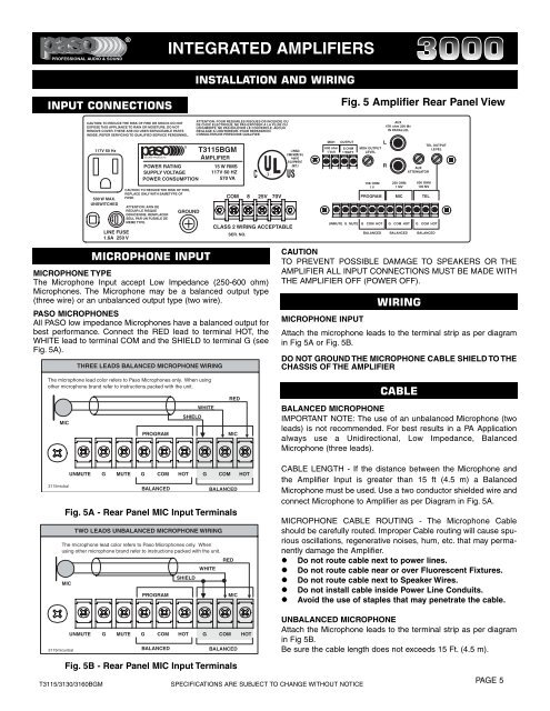
Fig. 5 Amplifier Rear Panel View<br />
L<br />
TEL OUTPUT<br />
MOH OUTPUT<br />
LEVEL<br />
LEVEL<br />
R<br />
10K OHM<br />
1 V<br />
PROGRAM<br />
UNMUTE G MUTE G COM HOT G<br />
AUX<br />
47K ohm 200 Mv<br />
IN PARALLEL<br />
AUX<br />
ATTENUATOR<br />
250 OHM 600 OHM<br />
1 MV 100 MV<br />
MIC TEL<br />
COM HOT G COM HOT<br />
BALANCED BALANCED BALANCED<br />
MICROPHONE INPUT<br />
MICROPHONE TYPE<br />
The Microphone Input accept Low Impedance (250-600 ohm)<br />
Microphones. The Microphone may be a balanced output type<br />
(three wire) or an unbalanced output type (two wire).<br />
PASO MICROPHONES<br />
All PASO low impedance Microphones have a balanced output for<br />
best performance. Connect the RED lead to terminal HOT, the<br />
WHITE lead to terminal COM and the SHIELD to terminal G (see<br />
Fig. 5A).<br />
THREE LEADS BALANCED MICROPHONE WIRING<br />
CAUTION<br />
TO PREVENT POSSIBLE DAMAGE TO SPEAKERS OR THE<br />
AMPLIFIER ALL INPUT CONNECTIONS MUST BE MADE WITH<br />
THE AMPLIFIER OFF (POWER OFF).<br />
WIRING<br />
MICROPHONE INPUT<br />
Attach the microphone leads to the terminal strip as per diagram<br />
in Fig 5A or Fig. 5B.<br />
DO NOT GROUND THE MICROPHONE CABLE SHIELD TO THE<br />
CHASSIS OF THE AMPLIFIER<br />
The microphone lead color refers to <strong>Paso</strong> Microphones only. When using<br />
other microphone brand refer to instructions packed with the unit.<br />
MIC<br />
PROGRAM<br />
SHIELD<br />
WHITE<br />
RED<br />
MIC<br />
CABLE<br />
BALANCED MICROPHONE<br />
IMPORTANT NOTE: The use of an unbalanced Microphone (two<br />
leads) is not recommended. For best results in a PA Application<br />
always use a Unidirectional, Low Impedance, Balanced<br />
Microphone (three leads).<br />
3115micbal<br />
UNMUTE<br />
G<br />
MUTE<br />
G COM HOT<br />
BALANCED<br />
The microphone lead color refers to <strong>Paso</strong> Microphones only. When<br />
using other microphone brand refer to instructions packed with the unit.<br />
MIC<br />
TWO LEADS UNBALANCED MICROPHONE WIRING<br />
PROGRAM<br />
G<br />
WHITE<br />
SHIELD<br />
COM<br />
BALANCED<br />
Fig. 5A - Rear Panel MIC Input Terminals<br />
RED<br />
MIC<br />
HOT<br />
CABLE LENGTH - If the distance between the Microphone and<br />
the Amplifier Input is greater than 15 ft (4.5 m) a Balanced<br />
Microphone must be used. Use a two conductor shielded wire and<br />
connect Microphone to Amplifier as per Diagram in Fig. 5A.<br />
MICROPHONE CABLE ROUTING - The Microphone Cable<br />
should be carefully routed. Improper Cable routing will cause spurious<br />
oscillations, regenerative noises, hum, etc. that may permanently<br />
damage the Amplifier.<br />
Do not route cable next to power lines.<br />
Do not route cable near or over Fluorescent Fixtures.<br />
Do not route cable next to Speaker Wires.<br />
Do not install cable inside Power Line Conduits.<br />
Avoid the use of staples that may penetrate the cable.<br />
3115micunbal<br />
UNMUTE<br />
G<br />
MUTE<br />
G COM HOT<br />
BALANCED<br />
G<br />
COM<br />
BALANCED<br />
HOT<br />
UNBALANCED MICROPHONE<br />
Attach the Microphone leads to the terminal strip as per diagram<br />
in Fig 5B.<br />
Be sure the cable length does not exceeds 15 Ft. (4.5 m).<br />
Fig. 5B - Rear Panel MIC Input Terminals<br />
T3115/3130/3160BGM<br />
SPECIFICATIONS ARE SUBJECT TO CHANGE WITHOUT NOTICE<br />
PAGE 5