Swipe-N-Clean 1.0 Complete - Jim Coleman Company
Swipe-N-Clean 1.0 Complete - Jim Coleman Company
Swipe-N-Clean 1.0 Complete - Jim Coleman Company

Create successful ePaper yourself
Turn your PDF publications into a flip-book with our unique Google optimized e-Paper software.
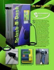
<strong>Swipe</strong>-N-<strong>Clean</strong> Operating Manual<br />
PROGRAMMING INSTRUCTIONS PUSH BUTTON CONTROLLER BOARDS (PBC)<br />
WASH – VAC – VENDOR<br />
Each PBC needs to be addressed with its designated unit and associated timer for that unit. This is<br />
accomplished by using a pattern of LED’s to set the location for computer to identify.<br />
The LED’s are numbered from S0 TO S9 and are associated with four other LED’s: MS, AUX1, AUX2, & RCV<br />
1. Disconnect the only two pin connector usually with a black and white pair of wires from the PBC board (See diagram of<br />
specific boards for location of pins)<br />
2. Disconnect power cable connector, the 10-pin connector on con1<br />
3. On the keypad depress and hold the 0 key.<br />
4. While holding the 0 key on the keypad reconnect the 10-pin connector to con 1. After the horn sounds release the 0<br />
key on keypad and check the setting of the function LED’s<br />
♦ 1030 Wash Bay PBC: Look 45° to the left of top of the gray plastic keypad connector and make sure the MS LED<br />
is the only function of the four available that is lit. (If it is not lit use the 8 key on the keypad to cycle the lights in<br />
the group until only the MS light is on)<br />
♦ 1036 VAC PBC: (the four light sequence is at the top left upper quarter of the circuit board after the S0-S9<br />
sequence) also, each type of vacuums gets a setting unique to its type i.e.; VAC: AUX2; SVAC: AUX2; FVAC:<br />
AUX1. Use the 8 Key to scroll to the desired setting.<br />
♦ 1037 VENDOR PBC: (MS, AUX1, AUX2 lights are not required and are omitted.) Vendors only need to be<br />
addressed to communicate w/timers. Go directly to Step #5 after depressing and holding the 0 key “…and the light<br />
pattern includes S8….”<br />
5. When the desired setting is verified on the four light sequences – Depress the 5 key on the keypad once and the light<br />
setting should now switch to a pattern that includes S8 LED being on. This is where the address setting for the PBC board<br />
associated with the unit in question is verified. Identify the number of this unit and match the on/off setting from the<br />
BAY, VAC, or VENDOR PBC address charts for PBC.<br />
6. When the desired lights have been matched and verified, Depress the 5 key on the keypad once again and the light<br />
settings should now switch to include the S9 LED being illuminated. This is where the address setting for the timer<br />
associated with the unit in question is verified. Identify the number of this unit and match the on/off settings from the<br />
BAY, VAC or VENDOR Timer address chart of PBC’s.)<br />
7. When the desired lights have been matched and verified, Depress the 5 key on the keypad to return to the four light<br />
sequence and now it should match the function desired. If all settings are correct, Depress the 1 key on the keypad to<br />
return to normal operating mode. After approximately 10 seconds running lights should return to PBC and the horn<br />
should sound.<br />
GETTING THE PBC AND TIMER TO RECOGNIZE EACH OTHER<br />
8. Remove the power connector from con 1 and communication connector from con 5 or 6 depending on the type of PBC.<br />
9. Timer: Remove power connector and communication connector.<br />
10. Replace power cable then communication cable (observe timer display starts scrolling immediately, 2-4 seconds).<br />
V-4<br />
. . . . . . . . . . PROGRAMMING INSTRUCTIONS