NT154V3-1.0 Instruction Manual
NT154V3-1.0 Instruction Manual
NT154V3-1.0 Instruction Manual

You also want an ePaper? Increase the reach of your titles
YUMPU automatically turns print PDFs into web optimized ePapers that Google loves.
TECSYSTEM S.r.l ®<br />
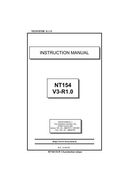
INSTRUCTION MANUAL<br />
NT154<br />
V3-R<strong>1.0</strong><br />
TECSYSTEM S.r.l.<br />
Via Cristoforo Colombo, 5/C<br />
20094 Corsico (MI)<br />
phone +39 - 02 - 48601011 / 4581861<br />
Fax: +39 - 02 – 48600783<br />
http://www.tecsystem.it<br />
R.0 16/06/03<br />
NT154 V3-R <strong>1.0</strong> protection relays
TECSYSTEM S.r.l ®<br />
INNOVATIONS INTRODUCED WITH THE NT154<br />
1. New hardware and software for a further improvement of immunity to disturbances.<br />
2. Reading rate increasing, indispensable for applications where fast temperature variations<br />
must be monitored.<br />
3. Intelligent control of alarm detecting relays which is able to exclude possible overtemperatures<br />
caused by an external disturbance without causing working problems<br />
or manual reset conditions.<br />
4. Detecting of a possible corruption of data stored in the memory (Ech) and default value<br />
reset for security.<br />
5. Storage in T.Max mode of possible alarms occurred from last reset and recording of<br />
possible sensors failures.<br />
6. Error detecting in case of wrong programming with specific indication of the wrong<br />
value couple.<br />
7. Possibility to return to previous programming step for a faster value modification.<br />
8. Safer programming block which can be activated just through the closing of an inner<br />
jumper.<br />
9. SCAN display mode to see, in sequence, the temperature and the state of the<br />
alarms for all channels.<br />
10. Wider temperature reading range: from 0 to 240°C<br />
2 NT154 V3-R <strong>1.0</strong> protection relays
TECSYSTEM S.r.l ®<br />
1) TECHNICAL SPECIFICATIONS<br />
POWER SUPPLY<br />
• Rated values 24-240 Vac-dc<br />
• Highest tolerable values 20-270 Vac-dc<br />
• Vdc with reversible polarities<br />
INPUTS<br />
COMMUNICATION<br />
• Not available<br />
OUTPUTS<br />
• 3 or 4 inputs RTD Pt100 -3 wires<br />
• Removable rear terminals<br />
• Input channels protected against electromagnetic<br />
noises and spikes<br />
• Sensor length cable compensation up to<br />
500 m (1mm²)<br />
TESTS AND PERFORMANCES<br />
• Assembling in accordance with CE rules<br />
• Protection against electrical noises<br />
CEI-EN50081-2/50082-2<br />
• Dielectric strength 2500 Vac for 1 minute<br />
from relays to sensors, relays to power<br />
supply, power supply to sensors<br />
• Accuracy ± 1% full scale value ± 1 digit<br />
• Ambient operating temperature from<br />
-20 °C to +60°C<br />
• Humidity 90% no-condensing<br />
• ABS self-extinguishing housing NORYL<br />
94VO<br />
• Frontal in polycarbonate IP65<br />
• Absorption 3VA<br />
• Data storage 10 years minimum<br />
• Digital linearity of sensor signal<br />
• Self-diagnostic circuit<br />
• Option protection treatment of electronic<br />
part<br />
DIMENSIONS<br />
• 96x96mm-DIN43700– depth140mm<br />
(terminal box included)<br />
• Panel cut-out 92x92mm<br />
• 2 alarm relays (ALARM-TRIP)<br />
• 1 alarm relay for fan control (FAN)<br />
• 1 alarm for sensor fault or working anomaly<br />
(FAULT)<br />
• Output contacts capacity: 5A-250 Vac<br />
res.<br />
DISPLAYING AND DATA MANAGEMENT<br />
• 1 display 13mm high with 3 digit for<br />
displaying temperatures and messages<br />
• 4 leds to show selected channel<br />
• 4 leds to display the state of the alarms<br />
for selected channel<br />
• Temperature monitoring from 0°C to<br />
240°C<br />
• 2 alarm thresholds for channels 1-2-3<br />
• 2 alarm thresholds for channel 4<br />
• 2 ON-OFF thresholds for fan control<br />
• Sensors diagnostic (Fcc-Foc)<br />
• Data storage diagnostic (Ech)<br />
• Programming access through front key<br />
• Automatic output from programming cycle<br />
after 1 minute of no-operation<br />
• Wrong programming automatic display<br />
• Possibility of setting automatic channels<br />
scanning, hottest channel, manual scanning<br />
• Maximum reached temperatures, alarm<br />
storage and sensor fault.<br />
• Frontal alarm reset push button<br />
NT154 V3-R <strong>1.0</strong> protection relays<br />
3
TECSYSTEM S.r.l ®<br />
2) MOUNTING<br />
Make a hole in the panel sheet with dimensions 92x92 mm.<br />
Firmly tighten the device with the enclosed fixing blocks.<br />
3) POWER SUPPLY<br />
NT154 control device has an UNIVERSAL supply, i.e. it can be indifferently fed from 24 to<br />
240 Vac-dc, regardless of polarities in Vdc.<br />
This peculiarity is obtained using a new-concept and new-designed tested feeder which<br />
relieves the technician of each concern for the correct supply Vac or Vdc.<br />
To terminal 41 must always be connected the ground.<br />
When the control device is directly fed from secondary winding of the transformer to be<br />
protected, it can be damaged by high-intensity overvoltages.<br />
These problems occur if the main switch is connected without load.<br />
Above mentioned problems are much more evident when the voltage is 220 Vac is directly<br />
taken from the transformer secondary bars and there is a fixed capacitor battery to<br />
phase the transformer itself.<br />
To protect the control device from line overvoltages, we suggest to use the electronic<br />
discharger PT73-220, designed by TECSYSTEM S.r.l. for this specific purpose.<br />
As alternative we suggest to use supply voltages from 24 Vac or, much better, 24<br />
Vdc.<br />
4) ELECTRICAL CONNECTIONS FOR ALARMS AND FAN<br />
Carry out the electrical connections on the removable rear terminals, after having removed<br />
them from the device.<br />
ALARM and TRIP relays switch only when the set temperature limits are reached.<br />
FAULT relay switches when the meter is fed, while gets de-energised when a fault occurs<br />
to Pt100 sensors, data memory fault (Ech) or when supply voltage is lacking.<br />
FAN contact can be used to check the cooling fans or it can be inserted in a transformer<br />
room conditioning circuit.<br />
5) TEMPERATURE SENSOR CONNECTION<br />
Each Pt100 temperature sensor has a white wire and two red wires (CEI 75.8 stardards).<br />
Fig. 1 shows the position inside the terminal box of central connection cables.<br />
Channel CH2 must always be referred to transformer central column.<br />
Channel CH4 must be referred either to the transformer core or to Pt100 sensor for room<br />
in case you want to control the temperature of transformer room using NT154 monitoring<br />
unit.<br />
4 NT154 V3-R <strong>1.0</strong> protection relays
TECSYSTEM S.r.l ®<br />
6) MEASURING SIGNAL TRANSFER<br />
All the measuring signal transfer cables for Pt100 must absolutely:<br />
• be separated from the power ones<br />
• be made with shielded cable and twisted conductors<br />
• have at least 0,5 mm² section<br />
• be twisted if there is no shield<br />
• be firmly fixed inside the terminal boxes<br />
• have tinned or silvered conductors<br />
TECSYSTEM S.r.l. has designed an own special cable to transfer the measuring<br />
signals, according to CEI standards, with all the protection requirements provided<br />
for : mod. CT-ES<br />
All “NT” series control devices have the sensor signal linearization, with a maximum error<br />
of 1% of full scale value.<br />
7) TEMPERATURE SENSOR DIAGNOSTIC<br />
In case of breaking of a temperature sensor mounted on the machine to be protected,<br />
FAULT relay immediately switches with the relevant indication of defective sensor on the<br />
corresponding channel.<br />
• Fcc for short-circuited sensor.<br />
• Foc for interrupted sensor<br />
To eliminate the message and reset Fault switching, it is necessary to verify Pt100 connections<br />
and, in case, replace the defective sensor.<br />
8) PROGRAMMED DATA DIAGNOSTIC<br />
In case of breaking of the internal storage or corruption of programmed data, just after<br />
switching on it appears Ech indication with the relevant reporting of the Fault contact.<br />
In this case, for safety reasons, the default parameters: Alarm Ch1-2-3= 90°C, Trip Ch1-<br />
2-3= 119°C, Ch4= Yes, Alarm Ch4= 120°C, Trip Ch4= 140°C, Ch-Fan= 1-2-3, Fan-on=<br />
70°, Fan-off= 60°, HFn= 000 are automatically reloaded.<br />
Eliminate Ech indication by pressing RESET and run programming to insert desired values.<br />
Finally turn off and turn on again the unit to verify the correct memory working; in case it<br />
is damaged and Ech still appears, please return the monitoring unit to Tecsystem for repair.<br />
9) TEMPERATURE DIAGNOSTIC<br />
If one of the temperature sensor detects a temperature higher than 1°C compared to set<br />
value as alarm limit, after approximately 5 seconds ALARM relay switches together with<br />
turning on of channel reference LED ALARM (CHn).<br />
When the release temperature limit is passed, TRIP relay switches together with turning<br />
on of channel reference LED TRIP (CHn).<br />
As soon as taken temperature returns to equal or lower values than set limit for ALARM<br />
and TRIP relays switching, they de-energise with consequent turning off of relevant<br />
LED’s.<br />
NT154 V3-R <strong>1.0</strong> protection relays<br />
5
TECSYSTEM S.r.l ®<br />
10) COOLING FAN CONTROL<br />
NT154 monitoring unit, if opportunely programmed, can control ON-OFF of transformer<br />
fans, according to set temperatures.<br />
Fans on machine can be driven in two different ways:<br />
• Using the temperatures taken by the sensors on three columns<br />
CHF 1.2.3<br />
(ex. ON at 80°C - OFF at 70°C)<br />
• Through an extra sensor (CH4/YES) for the room temperature inside the transformer<br />
box.<br />
CHF 4<br />
(ex. ON at 40°C - OFF at 30°C)<br />
11) FAN TEST<br />
It is possible, through programming (HFn), to lay down that fans are activated for 5 minutes<br />
each “xxx” hours, regardless of column or room temperature values (ex.: with HFn=001<br />
fans are activated for 5 minutes each hour).<br />
This function has the aim to periodically verify the working of the fans and their control apparatus<br />
during long idle periods.<br />
Loading 000 value,this function is inhibited.<br />
12) DISPLAY MODE<br />
Pressing MODE key, display mode is loaded:<br />
• SCAN: control device displays in scansion all activated channels (each 2 seconds)<br />
• AUTO: control device automatically displays the hottest channel<br />
• MAN: channel temperature manual reading through cursor keys<br />
• T.MAX: monitoring unit displays the highest temperature reached by the sensors and<br />
possible alarm or fault situations occurred after last reset.<br />
Select channels with !", delete values with RESET.<br />
13) WORKING PROGRAM CONTROL<br />
To check the programmed temperature values,shortly press PRG key. PRG indication appears<br />
for 2 seconds, confirming entering in program vision mode.<br />
By repetedly pressing PRG key, all the previously loaded values are rolled in sequence.<br />
After 1 minute of keyboard no-operation, display-programming procedure will be automatically<br />
left.<br />
To end display programming, press ENT key.<br />
14) LAMP TEST<br />
We suggest to regularly carry out control device LED test.<br />
For this operation, shortly press TEST key; all displays turn on for 2 seconds.<br />
If one of the LED’s should not work, we kindly ask you to return the monitoring unit<br />
to TECSYSTEM (Led RS is not available on monitoring units without optional module)<br />
6 NT154 V3-R <strong>1.0</strong> protection relays
TECSYSTEM S.r.l ®<br />
15) ALARM RELAY TEST<br />
This function allows to carry out a test on relays working, without having to use further devices.<br />
To start test procedure you have to keep pressed TEST key for about 5 seconds;TST indication<br />
appears for 2 seconds, confirming entering in Relays Test mode.<br />
Blinking led shows the relay to test; using the cursors you can select the desired one.<br />
Press SET and RESET keys to energise and de-energise the relay to test; display will<br />
show ON-OFF.<br />
After 1 minute keyboard no-operation, RELAYS TEST procedure will be automatically left.<br />
To end RELAYS TEST procedure, press TEST key.<br />
16) ALARM RELAY EXCLUSION<br />
If you want to exclude the ALARM signal press RESET key: relay de-energises itself and<br />
LED ALARM, which was fixed, will start to blink.<br />
Exclusion system is automatically disconnected when the temperature goes under the<br />
ALARM threshold.<br />
17) IMPORTANT NOTICE<br />
Before carrying out the insulation test on the switchboard where the monitoring u-<br />
nit is mounted, you have to disconnect it from the mains in order to avoid serious<br />
damages.<br />
18) FRONT PANEL<br />
Messages and temperature<br />
display<br />
Display mode<br />
Alarms<br />
selected<br />
channel<br />
Selected<br />
channel<br />
Prg/RelaysTest<br />
mode<br />
Keyboard<br />
NT154 V3-R <strong>1.0</strong> protection relays<br />
7
TECSYSTEM S.r.l ®<br />
19) PROGRAMMING<br />
NOTE: LED PRG-ON ON: PROGRAM MODIFICATION<br />
LED PRG-ON OFF: PROGRAM DISPLAY.<br />
N° PRESS EFFECT NOTES<br />
1 PRG/SET<br />
Keep pressed PRG key until PRG-ON led<br />
turns on. After PRG indication, it appears<br />
ALARM threshold for CH 1-2-3<br />
2 Load desired threshold<br />
3 PRG/SET It appears TRIP threshold for CH 1-2-3<br />
4 Load desired threshold<br />
If NOP appears<br />
please see<br />
“Programming block” paragraph<br />
5 PRG/SET led CH 4 blinks Enabling CH 4<br />
6 Load YES or NO<br />
with YES CH 4 is connected<br />
with NO CH 4 is disconnected<br />
7 PRG/SET It appears ALARM threshold for CH 4 if CH 4=NO goes to point 11<br />
8 Load desired threshold<br />
9 PRG/SET Appear TRIP threshold for CH 4<br />
10 Load desired threshold<br />
11 PRG/SET<br />
led Fan blinks and channel leds to which fan<br />
is referred turn on<br />
12 Select NO, CH 1-2-3 or CH 4 (if CH 4 YES)<br />
NO: disabled fan,<br />
Goes to point 20<br />
13 PRG/SET Display shows ON FAN turning on<br />
14 PRG/SET It appears ON threshold for FAN<br />
15 Load desired threshold<br />
16 PRG/SET Display shows OFF FAN turning off<br />
17 Load desired threshold<br />
18 PRG/SET Display shows HFn<br />
Fan cyclic test for 5 minutes e-<br />
ach “n” hours<br />
19 Load desired number of hours 000= disabled function<br />
20 PRG/SET Display shows END Programming end<br />
21 ENT Loaded data storage and programming exit<br />
22 PRG/SET Return to step 1<br />
Err: wrong programming for values<br />
indicated by leds (note 2)<br />
NOTE:<br />
1) It is possible to return to previous step by pressing MODE key.<br />
2) if pressing ENT it appears “Err”, it means that one of the following mistakes<br />
has been made: ALARM ≥ TRIP or FAN-OFF ≥ FAN-ON.<br />
Press PRG to return to step 1 and correct the data.<br />
3) After 1 minute of keyboard no-operation, programming is left without data<br />
storage.<br />
8 NT154 V3-R <strong>1.0</strong> protection relays
TECSYSTEM S.r.l ®<br />
20) PROGRAMMING RE-ENABLING IN CASE OF BLOCK (Prg no)<br />
If pressing PRG to enter programming (step 1) “NOP” indication appears, it means that<br />
programming access jumper inside the unit has been removed and therefore this function<br />
is blocked. To reset programming access, mount the jumper as shown in the figure<br />
below.<br />
Disabled programming<br />
Enabled programming<br />
21) WARRANTY<br />
“NT” series monitoring units are covered by a 12-month warranty starting from the<br />
delivery date on the device itself.<br />
This warranty is valid if device should be damaged by causes which can be attributed to<br />
TECSYSTEM S.r.l., such as manufacturing defects or improper calibration.<br />
The warranty is not valid if the monitoring unit would be tampered or if it would be damaged<br />
by supply voltages beyond the highest working limits (20÷270 Vac-dc). The warranty<br />
is not valid if the device would be burnt out by too many transient voltage peaks.<br />
In this case TECSYSTEM S.r.l. does not answer for damages caused by faulty or defective<br />
monitoring units. All the deliveries (go and back) as well as the repair and servicing<br />
costs for the device, will be at Customer’s expenses, reckoned according to ANIMA,<br />
Col. C rates.<br />
In case of contest, may only be institued the Milan court.<br />
The warranty is always FREE OUR DOMICILE in CORSICO.<br />
22) EXTENSION CABLE FOR Pt100 TECHNICAL SPECIFICATIONS<br />
Cable 20xAWG 20/19 cu/stg<br />
Section 0,55 mm²<br />
Insulation PVC105 flame-retardant<br />
Standards CEI 20.35 IEC 332.1<br />
Max. working temperature : 105°C<br />
Structure: 4 terns composed of three numbered wires (1-1-1.........4-4-4)<br />
Twisted and coloured wires Red-Red-White<br />
Shield in cu/stg<br />
Sheath in flame-retardant PVC<br />
External Diameter 9,0 mm<br />
Standard packaging in skein of 100 m<br />
NT154 V3-R <strong>1.0</strong> protection relays<br />
9
TECSYSTEM S.r.l ®<br />
FAULT DIAGNOSTIC<br />
CAUSES AND REMEDIES<br />
Monitoring unit doesn’t turn on, even if there<br />
is power supply and the terminals are fed.<br />
CH4 is in FAULT FOC<br />
(only 3 sensors Pt100 are connected)<br />
One of three/four channels is in FAULT for<br />
FOC/FCC<br />
When turning on, indication “ECH” appears.<br />
All the sensors are in FCC.<br />
Temperature indicated by one or more channel<br />
is wrong.<br />
Connector not well placed inside its seat.<br />
Connection cables are not tightened in the<br />
terminal. Burnt out feeder.<br />
Take out and give supply again.<br />
Wrong programming of the monitoring unit<br />
with CH4/no.<br />
Repeat programming.<br />
Check Pt100 sensor connections. Possible<br />
defective sensor.<br />
Replace the damaged sensor.<br />
A strong disturbance damaged the stored data.<br />
Please refer to paragraph 8.<br />
If this problem should persist, please contact<br />
TECSYSTEM S.r.l Technical Department.<br />
Wrong sensor connections. Terminal box<br />
connected inside out.<br />
Check connections and terminal box.<br />
Contact TECSYSTEM S.r.l. Technical Department<br />
Sudden trip of main switch. Temperature is<br />
on standard levels. Just a channel caused<br />
the trip.<br />
Verify through T.MAX function possible defective<br />
sensors.<br />
Replace the sensor. Check the measuring<br />
signal terminal boxes.<br />
10 NT154 V3-R <strong>1.0</strong> protection relays
TECSYSTEM S.r.l ®<br />
FIG.1<br />
NT154 ELECTRICAL CONNECTIONS<br />
Pt100 INPUTS<br />
CH 1 CH 2 CH 3 CH 4<br />
13 14 15 16 17 18 19 20 21 22 23 24<br />
ALARM RELAY OUTPUTS<br />
1 2 3 4 5 6 7 8 9 10 11<br />
ALARM TRIP FAULT FAN<br />
Pt100<br />
42<br />
41<br />
40<br />
POWER SUPPLY<br />
24-240 VAC-VDC<br />
WHITE<br />
RED<br />
RED<br />
NT154 V3-R <strong>1.0</strong> protection relays<br />
11
TECSYSTEM S.r.l ®<br />
TEST DECLARATION FOR NT154<br />
This device has passed a test at the origin, according to the following procedure:<br />
N° Description<br />
1 Mounting card check<br />
2 Input working check<br />
3 Relay contacts and output check<br />
4 Push-button working check<br />
5 Check lamp<br />
6 Calibration at 0 and 200°C<br />
7 Software working check<br />
8 Burn-in min. 24h<br />
Delivery Date: ……………<br />
12 NT154 V3-R <strong>1.0</strong> protection relays