Catalog 2008 Sec M Pendant Stations - Springer Controls
Catalog 2008 Sec M Pendant Stations - Springer Controls
Catalog 2008 Sec M Pendant Stations - Springer Controls
- No tags were found...
You also want an ePaper? Increase the reach of your titles
YUMPU automatically turns print PDFs into web optimized ePapers that Google loves.
PENDANT STATIONSCHARLIE PENDANT - DIMENSIONSM3Charlie <strong>Pendant</strong> - Detailed Drawing ** See page M4 for spare part pricing<strong>Springer</strong> <strong>Controls</strong> Company • 96074 Chester Road, Yulee, FL 32097 • (904) 225-0575 • Fax: (904) 225-9084 • www.springercontrols.comM3
PENDANT STATIONSCHARLIE PENDANT - ACCESSORY PARTSM 4Spare PartsReference Illustration Description Part No. Price01 Spiral Cable Clamp PRPS0025PE $32.00081 N.O. Switch1 N.C. SwitchPRSL1000PIPRSL1001PI$40.0009Rubber Boot for DoublePush-Button (without buttons)PRG0020PE $20.00111-Speed Double Switch2-Speed Double SwitchPRSL1002PIPRSL1003PI$52.00$90.0014Emergency StopMushroom Push-ButtonPRSL1011PI $94.0017 Button for Double Push-Button PRTA2xxxPI* $12.5018Spring Return Selector Switch (on-off)Selector Switch (on-off)Spring Return 3-Position Selector Switch3-Position Selector SwitchPRSL1015PIPRSL1016PIPRSL1026PIPRSL1027PI$77.00$90.0019 Button for Single Push-Button PRTA1xxxPI* $11.0020 Blanking Plug PRSL1023PI $32.0021 Single Push-Button ( without button) PRSL1023PI $22.0023Red Pilot LightYellow Pilot LightGreen Pilot LightPRSL1012PIPRSL1013PIPRSL1014PI$63.0024 Key Selector Switch (on-off) PRSL1017PI $99.0025 Lamp Holder (12V or 24V only) PRSL1004PI $63.00*Standard ButtonsPRTA1000PIPRTA2000PIPRTA1001PIPRTA2001PIPRTA1002PIPRTA2002PIPRTA1003PIPRTA2003PIPRTA1004PIPRTA2004PIPRTA1005PIPRTA2005PIPRTA1006PIPRTA2006PIPRTA1007PIPRTA2007PIPRTA1010PIPRTA2010PIPRTA1011PIPRTA2011PIPRTA1012PIPRTA2012PIPRTA1013PIPRTA2013PIPRTA1030PIPRTA2030PIDiscount Schedule SC-20M4 <strong>Springer</strong> <strong>Controls</strong> Company • 96074 Chester Road, Yulee, FL 32097 • (904) 225-0575 • Fax: (904) 225-9084 • www.springercontrols.com
PENDANT STATIONSCHARLIE PENDANT - TECHNICAL DATATechnical SpecificationsConformity to Community Directives 73/23/CEE 93/68/CEEConformity to Standards EN 60204-1EN 60529Ambient TemperatureStorageOperationalProtection Degree IP 65Insulation CategoryClass IICable EntryCable Clamp PG16Operating PositionsAny PositionWeight~ 320gApprovalsCEEN 60947-1EN 418-40°C / +70° C-25°C / +70° CEN 60947-5-1EN 50013 IEC 536M5Technical Specifications of Contact SwitchesUtilisation Category AC 15Rated Operational Current3 ARated Operational Voltage250VRated Thermal Current10 ARated Insulation Voltage 500V ~Mechanical Life0,5 x 10 6 operationsTerminal Referencing According to EN 50013ConnectionsScrew-Type TerminalsApprovalsCE - UL - cULOperating Force2.0 - 2.4 lbsFeatures of the Contact SwitchesThe single switches PRSL1000PI and PRSL1001PI have 1 N.C. contacts with 2 connecting terminals.The double switch PRSL1002PI (1-speed)) has:1 N.O. contact with 1 connecting terminal for the first speed for each opposite function - 1 single terminal for bothfunctionsThe double switch PRSL1003PI (2-speeds) has:1 N.O. contact with 1 connecting terminal for the first speed for each opposite function - 1 N.O. contact with 1connecting terminal for the second speed for both functions - 1 single terminal for both functions.All N.C. contacts are of the positive opening operation type.The switches have the following reference for internal wiring.PRSL1000PI PRSL1001PI PRSL1002PI PRSL1003PI<strong>Springer</strong> <strong>Controls</strong> Company • 96074 Chester Road, Yulee, FL 32097 • (904) 225-0575 • Fax: (904) 225-9084 • www.springercontrols.comM5
PENDANT STATIONSCHARLIE PENDANT - REQUEST FORMRequest Form for Non-Standard <strong>Pendant</strong> <strong>Stations</strong>M7Instructions:• Write the number corresponding to the control element required (broken line box). When buttons are required and whennecessary, mark the direction of the arrow into the corresponding circle.• Selector Switches PRSL1026PI and PRSL1027PI can be assembled only in the center-top position. (3 position switches)• Write the number corresponding to the single or double switches.• Mark the appropriate box to show either the spiral cable clamp or the cable clamp (PG16). Cable clamp comesstandard.Control Elements1(green)814PRSL1009PI - Mushroom Pushbutton20PRSL1017PI - Key Selector Switch (on-off)2(green)915PRSL1012PI - Red Pilot Light21PRSL1026PI - Spring Return 3 Pos. Selector Sw.3(yellow)1016PRSL1013PI - Yellow Pilot Light22PRSL1027PI - 3 Position Selector Switch4(red)1117PRSL1014PI - Green Pilot Light23PRSL1023PI - Blanking Plug51218PRSL1015PI - Spring Return Selector Sw (on-off)24PRSL1024PI -Spring Return Key Selector Sw. (2 pos.)61319PRSL1016PI - Selector Switch (on-off)7Single Switches1PRSL1000PI - 1 N.O.2PRSL1001PI - 1 N.C.3PRSL1004PI - Lamp Holder (12V or 24V)Double Switches1PRSL1002PI - 1 speed2PRSL1002PI - 2 speedRemarks:..........................................................................................................................................................................................................................................................................................................................................................................................................................................................................................................................................................................................................................................................................................................................................................................................................................................................................................................................................................................................................................................................................................................................................................................................................................................................................................................................................................................................................................................................................................................................................................................................<strong>Springer</strong> <strong>Controls</strong> - Fax: 904-225-9084<strong>Springer</strong> <strong>Controls</strong> Company • 96074 Chester Road, Yulee, FL 32097 • (904) 225-0575 • Fax: (904) 225-9084 • www.springercontrols.comM7
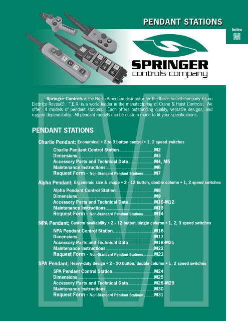
PENDANT STATIONSALPHA PENDANT CONTROL STATIONM 8Alpha <strong>Pendant</strong> Control StationThe Alpha Series <strong>Pendant</strong> Station is the latestergonomic design in 2 column pendant stations. Using symbols forbutton identification, this rubber gasketed unit provides a solid feel andimmediate response. Available in 1 or 2 speeds and multiples up to12 buttons, it is a very compact, lightweight station. A NEMA 4 ratedpolycarbonate enclosure is a striking yellow and black design. It providesthe operator with a pendant that fits firmly in the hand but will not createfatigue to the operator.• Convenient, ergonomic size & shape• 2 to 12 button, double column• 1, 2 speed switches• IP65 ratedAlpha <strong>Pendant</strong> - Part No. & Pricing*No. ButtonsE-StopAssemblyStart/Reset 1 SpeedStandardPart No.Price1 N.C. 1 N.O. 1 N.O. + 1 N.O. + com2 2 PF38020001 $197.003 1 2 PF38030001 $278.004 1 1 2 PF38040002 $305.004 4 PF38040004 $231.005 1 4 PF38050003 $312.006 1 1 4 PF38060001 $513.008 1 1 6 PF38080001 $542.009 1 8 PF38090001 $569.0010 1 1 8 PF38100001 $643.0012 1 1 10 PF38120001 $672.00* Custom units available - Part number assigned by factory; #PF38 _ _ J _ _ _ (see request form on page M14)Discount Schedule SC-20M8 <strong>Springer</strong> <strong>Controls</strong> Company • 96074 Chester Road, Yulee, FL 32097 • (904) 225-0575 • Fax: (904) 225-9084 • www.springercontrols.com
PENDANT STATIONSALPHA PENDANT CONTROL STATION - DIMENSIONSAlpha <strong>Pendant</strong> Control Station - DimensionsM9CDB EANo. ofButtonsWeight(lbs.)Overall Dimensions (in)A B C D E2, 4 1.04 15.04 2.95 6.65 8.66 2.366, 8 1.59 18.11 2.95 6.65 11.89 2.3610, 12 1.96 21.14 2.95 6.65 15.04 2.36Standard Alpha Button Configuration* 2, 3, 5, 12 Alpha <strong>Pendant</strong>s also available<strong>Springer</strong> <strong>Controls</strong> Company • 96074 Chester Road, Yulee, FL 32097 • (904) 225-0575 • Fax: (904) 225-9084 • www.springercontrols.comM9
PENDANT STATIONSALPHA PENDANT - ACCESSORY PARTSM11Spare PartsReference Illustration Description Part No. Price01 Hook PRGA0012PE $5.5002 Cable Sleeve PRSL0145PE $68.00081213Emergency StopMushroom Push-ButtonButton forDouble Push-ButtonRubber for Double Push-Button(without buttons)PRSL1011PI $94.00PRTA2xxxPI(see standard buttons)$12.50PRG00020PE $20.00151-Speed Double Switch PRSL1002PI $52.002-Speed Double Switch PRSL1003PI $90.0021 Button for Single Push-ButtonPRTA1xxxPI(see standard buttons)$11.0022Single Push-Button(without Button)PRSL1010PI $22.0023 Blanking Plug PRSL1023PI $32.0025Red Pilot LightYellow Pilot LightGreen Pilot LightPRSL1012PIPRSL1013PIPRSL1014PI$63.0027Spring Return Selector Switch (on-off)Maint. Selector Switch (on-off)Spring Return 3-Position Selector SwitchMaint. 3-Position Selector SwitchPRSL1015PIPRSL1016PIPRSL1026PIPRSL1027PI$77.00$90.0028 Maint. Key Selector Switch (on-off) PRSL1017PI $99.0031 Lamp Holder (12V or 24V only) PRSL1004PI $63.00331 N.O. Switch1 N.C. SwitchPRSL1000PIPRSL1001PI$40.00Discount Schedule SC-20<strong>Springer</strong> <strong>Controls</strong> Company • 96074 Chester Road, Yulee, FL 32097 • (904) 225-0575 • Fax: (904) 225-9084 • www.springercontrols.comM11
PENDANT STATIONSNOTESM15<strong>Springer</strong> <strong>Controls</strong> Company • 96074 Chester Road, Yulee, FL 32097 • (904) 225-0575 • Fax: (904) 225-9084 • www.springercontrols.comM15
PENDANT STATIONSNPA PENDANT STATIONM 16NPA <strong>Pendant</strong> StationThe NPA Series <strong>Pendant</strong> Station is the leader inversatility and rugged design. With a choice of operators from 2 to 12,and a selection of up to 3 speed contacts, selector switches and pilotlights as well as potentiometers, the NPA leads the way for the industry.Economical in cost, flexible in choice of operators, and using the latestin new polymers, it has become the standard both indoors or outside inrugged weather.• Custom availability• 2 to 12 button, single column• 1, 2, 3 speed switches• IP65 ratedNPA <strong>Pendant</strong> Station - Part No. & Pricing*No. ButtonsE-StopAssemblyStart/Reset 1 SpeedStandardPart No.Price1 N.C. 1 N.O. 1 N.O. + 1 N.O. + com2 2 PF03020005 $206.003 1 2 PF03030004 $327.004 1 1 2 PF03040105 $365.004 4 PF03040022 $426.006 1 1 4 PF03060293 $479.008 1 1 6 PF03080201 $583.0010 1 1 8 PF03100334 $675.0012 1 1 10 PF03120282 $764.00* Custom units available - part number assigned by factory; PF03 _ _ J _ _ _. See request form on page M23.Discount Schedule SC-20M16 <strong>Springer</strong> <strong>Controls</strong> Company • 96074 Chester Road, Yulee, FL 32097 • (904) 225-0575 • Fax: (904) 225-9084 • www.springercontrols.com
PENDANT STATIONSNPA PENDANT - DIMENSIONSNPA <strong>Pendant</strong> - DimensionsM17EDABCFNo. ofButtonsWeight(lbs)Overall Dimensions (inches)A B C D E F2 .99 11.50 5.51 3.00 2.76 3.90 3.433 1.21 13.11 7.13 3.00 2.76 3.90 3.434 1.43 14.65 8.74 3.00 2.76 3.90 3.436 1.98 18.07 12.09 3.00 2.76 3.90 3.438 2.65 23.82 15.47 3.27 2.76 3.90 4.5710 3.09 26.97 18.66 3.27 2.76 3.90 4.5712 3.75 30.35 22.05 3.27 2.76 3.90 4.57Standard NPA <strong>Pendant</strong>s4 ButtonPF030401054 ButtonPF030400226 ButtonPF030602938 ButtonPF0308020110 ButtonPF03100334- 2, 3, 12 button NPA <strong>Pendant</strong>s also available- Custom <strong>Pendant</strong>s available; Part number assigned by <strong>Springer</strong> <strong>Controls</strong>.<strong>Springer</strong> <strong>Controls</strong> Company • 96074 Chester Road, Yulee, FL 32097 • (904) 225-0575 • Fax: (904) 225-9084 • www.springercontrols.comM17
PENDANT STATIONSNPA PENDANT ACCESSORY PARTSM 18NPA <strong>Pendant</strong> - Detailed DrawingM18 <strong>Springer</strong> <strong>Controls</strong> Company • 96074 Chester Road, Yulee, FL 32097 • (904) 225-0575 • Fax: (904) 225-9084 • www.springercontrols.com
PENDANT STATIONSNPA PENDANT - STANDARD BUTTONSM 20Standard ButtonsSquare buttons used on standard NPA units. Round or disk style button used on "dust-tight" button (PRSL0550UL).Custom Engraving available $20.00 each (list).M20 <strong>Springer</strong> <strong>Controls</strong> Company • 96074 Chester Road, Yulee, FL 32097 • (904) 225-0575 • Fax: (904) 225-9084 • www.springercontrols.com
PENDANT STATIONSNPA PENDANT - TECHNICAL SPECIFICATIONSM21Technical SpecificationsConformity to Community Directives 73/23/CEE 93/68/CEEConformity to StandardsAmbient TemperatureEN 60204-1EN 60529StorageOperationalEN 60947-1EN 418-40°C / +70° C-25°C / +70° CEN 60947-5-1EN 50013 IEC 536Protection Degree IP 65Insulation CategoryCable EntryOperating PositionsWeightClass II2 - 6 buttons; Rubber Cable Sleeve (Ø 10÷18 mm)8 - 12 buttons; Rubber Cable Sleeve (Ø 17÷ 26 mm)Any Position~ 320gApprovalsTechnical Specifications of Contact SwitchesUtilisation Category AC 15Rated Operational CurrentRated Operational VoltageRated Thermal Current3 A250V10 ARated Insulation Voltage 500V ~Mechanical Life0,5 x 10 6 operationsTerminal Referencing According to EN 50013ConnectionsScrew-Type TerminalsApprovals<strong>Springer</strong> <strong>Controls</strong> Company • 96074 Chester Road, Yulee, FL 32097 • (904) 225-0575 • Fax: (904) 225-9084 • www.springercontrols.comM21
PENDANT STATIONSNPA PENDANT - MAINTENANCE INSTRUCTIONSM 22Use & Maintenance InstructionsThe NPA <strong>Pendant</strong> Control Station is an electromechanical device for low voltage control circuits (EN 60947-1, EN60947-5-1)to be used as electrical equipment on machines (EN 60204-1) in compliance with the fundamental requirements of the LowVoltage Directive 73/23/CEE and of the Machine Directive 89/392/CEE.The pendant station is designed for industrial use and also for use under particularly severe climactic conditions (operationaltemperature -25°C to +70°C, suitable for use in tropical environment). The equipment is not suitable for use in environmentswith potentially explosive atmosphere, corrosive agents or a high percentage of sodium chloride (saline fog). Oils, acids orsolvents may damage the equipment.The switches are designed for auxiliary control of contactors or electromagnetic loads (utilisation category AC-15 accordingto EN 60947-5-1). Do not connect more than one phase to each switch. Do not oil or grease the control elements or theswitches.The installation of the pendant station shall be carried out by an expert and trained personnel. Wiring shall be properly doneaccording to current instructions.Prior to installation and the maintenance of the pendant station, the main power of the machinery shall be turned off.Steps for the proper installation of the pendant station• remove the screws on the lower cover to open the pendant station• cut the variable selection rubber cable sleeve and insert the cable tight enough to guarantee protection against water and/or dust.• fix the cable to the cable sleeve using a cable tie (not supplied).• strip the cable to a length suitable for wiring the switches• tape the stripped part of the cable• fix the cable inside the pendant station using the cable clamp• connect all the switches according to the contact scheme printed on the switches (tighten the wires into the terminals witha torque equal to 0.8 Nm; insertability of wires into the switch terminals equal to 2 x 1.5mm² - 1 x 2.5mm²).• close the pendant station checking the proper positioning of the rubber in the cover and of the “O”rings• put the rubber caps for the screws into the holes in the lower cover.Additional steps for mounting / replacing control / signalling bulbs into the lamp holders• push the two clips on the sides of the lamp holder to remove it from the central part of the pendant station• put the bayonet-type bulb into its seat (use BA9s, 125V-2.6W (max) bulbs)• assemble the lamp holder on the central part of the pendant station checking that the two clips are properly coupledPeriodic maintenance steps• check the proper tightening of the screws of the enclosure• check the proper tightening of the switch terminal screws• check all wiring (in particular where wires clamp into the switches)• check the conditions of the rubber fit into the lower cover of the rubber of the control elements and of the cable sleeve.• check that the plastic enclosure of the pendant station is not brokenIn case any component of the pendant station is modified, the validity of the markings and the guarantee on the equipmentare annulled. Should any component need replacement, use original spare parts only.<strong>Springer</strong> <strong>Controls</strong> declines all responsibility for damages caused by the improper use or installation of the equipment.M22 <strong>Springer</strong> <strong>Controls</strong> Company • 96074 Chester Road, Yulee, FL 32097 • (904) 225-0575 • Fax: (904) 225-9084 • www.springercontrols.com
PENDANT STATIONSNPA PENDANT - REQUEST FORMRequest Form for Non-Standard NPA <strong>Pendant</strong> <strong>Stations</strong>Instructions:• Fill in the <strong>Pendant</strong> Station scheme for the number of control elements required (2, 3, 4, 6, 8, 10 buttons)• Write the number corresponding to the control element required (broken line box). When buttons are requiredand when necessary, mark the direction of the arrow into the corresponding circle. In case buttons differentfrom those listed below are needed, fill in the number code required. (Button selection on page M20)• Write the number corresponding to the switches required, keeping in mind that it is possible to assemble upto two switches number 2 & 3 under each control element, but only one of the other switches.• Circle the box corresponding to the type of buttons required (rectangular or disks).• Mark the rectangular box between the push-buttons when the mechanical interlock is required.• Mark the appropriate box to show where the cable sleeve and the hook must be assembled (top or bottom)Control ElementsHookCable SleeveSwitchesMechanical InterlockControl ElementsPRTA_________PIM231815 22SwitchesControl Elements2916 23Mechanical InterlockSwitchesPRTA_________PIControl Elements31017 24Mechanical InterlockPRTA_________PI41118 25SwitchesControl Elements51219 26Mechanical InterlockPRTA_________PI613 20 27SwitchesControl Elements714 21 28Mechanical InterlockPRTA_________PISwitchesControl Elements2930313233PRSL0500UL - Emergency StopMushroom PushbuttonPRSL0512UL - Impulse MushroomPushbuttonPRSL0513UL - 3 PositionKey Selector SwitchPRSL0514UL - 3 PositionSelector SwitchPRSL0515UL - Red Pilot LightSwitches12345PRSL0501UL - Lamp HolderPRSL0502UL - 1 N.C. SwitchPRSL0503UL - 1 N.O. Switch673435363738PRSL0504UL - 1 Speed1 N.O.+1 N.C.+1 N.O. simultaneousPRSL0505UL - 2 Speed1 N.O.+1 N.C.+1 N.O. sequencedPRSL0516UL - Green Pilot LightPRSL0517UL - Blanking PlugPRSL0519UL - Spring Return - 3 pos.Selector SwitchPRSL0520UL - Key MushroomPushbuttonPRSL0521UL - Yellow Pilot LightPRSL0506UL - 1 Speed3 N.O. simultaneousPRSL0507UL - 1 Speed3 N.O. sequencedButtons (circle)1RectangularButtons2 Disks (dust-tight)Mechanical InterlockSwitchesMechanical InterlockSwitchesMechanical InterlockSwitchesMechanical InterlockSwitchesMechanical InterlockCable SleevePRTA_________PIControl ElementsPRTA_________PIControl ElementsPRTA_________PIControl ElementsPRTA_________PIControl ElementsPRTA_________PIHookRemarks:...................................................................................................................................................................................................................................................................................................................................................................................................................................................................................................................................................................................................................................<strong>Springer</strong> <strong>Controls</strong> Company • 96074 Chester Road, Yulee, FL 32097 • (904) 225-0575 • Fax: (904) 225-9084 • www.springercontrols.comM23
PENDANT STATIONSSPA PENDANT CONTROL STATIONM 24SPA <strong>Pendant</strong>The SPA Series <strong>Pendant</strong> is a rugged 2 column designwith rubber bumper protection around every 4 button section. Withmillions in use around the world this unit has proven to be a workhorsein the environment of steel mills and heavy machinery. Available up to20 buttons with NEMA 12 rating and 1 or 2 speed operators, selectorswitches and indicators.• Rugged, Heavy-Duty Design• 2 to 20 button, double column• 1, 2 speed switches• IP65 ratedSPA <strong>Pendant</strong> - Part No. & Pricing*No. ButtonsE-StopAssemblyStart/Reset 1 SpeedStandardPart No.Price1 N.C. 1 N.O. 1 N.O.2 2 PF02020007 $284.003 1 2 PF02040185 $500.004 1 1 2 PF02040241 $500.006 1 1 4 PF02060355 $663.008 1 1 6 PF02080237 $798.0010 1 1 8 PF02100324 $912.0012 1 1 10 PF02120306 $1047.00* Units 13 through 20 available along with custom units. Part numbers assigned by factory; PF02 _ _ J _ _ _.See request form on page M31.Discount Schedule SC-20M24 <strong>Springer</strong> <strong>Controls</strong> Company • 96074 Chester Road, Yulee, FL 32097 • (904) 225-0575 • Fax: (904) 225-9084 • www.springercontrols.com
PENDANT STATIONSSPA PENDANT - DIMENSIONSSPA <strong>Pendant</strong> Control Station - DimensionsM25No. ofButtonsWeight(lbs)Overall Dimensions (inches)A B C D E2 1.15 12.52 5.20 3.7 2.52 4.564 1.54 14.57 7.24 3.7 2.52 4.566 1.94 16.14 9.29 3.7 2.52 4.568 2.29 18.66 11.34 3.7 2.52 4.5610 2.87 20.71 13.39 3.7 2.52 4.5612 3.04 22.76 15.43 3.7 2.52 4.5614 3.42 24.80 17.48 3.7 2.52 4.5616 3.77 26.85 19.53 3.7 2.52 4.5618 4.17 28.90 21.57 3.7 2.52 4.5620 4.52 30.95 23.62 3.7 2.52 4.56Standard SPA <strong>Pendant</strong>s4 ButtonPF020402416 ButtonPF020603558 ButtonPF0208023710 ButtonPF02100324- 2, 3, 12 button standard units available- 12 - 20 button pendants and custom pendants available - see page M31<strong>Springer</strong> <strong>Controls</strong> Company • 96074 Chester Road, Yulee, FL 32097 • (904) 225-0575 • Fax: (904) 225-9084 • www.springercontrols.comM25
PENDANT STATIONSSPA PENDANT - ACCESSORY PARTSM 26SPA <strong>Pendant</strong> - Detailed DrawingM26 <strong>Springer</strong> <strong>Controls</strong> Company • 96074 Chester Road, Yulee, FL 32097 • (904) 225-0575 • Fax: (904) 225-9084 • www.springercontrols.com
PENDANT STATIONSSPA PENDANT - ACCESSORY PARTSSpare PartsM27Reference Illustration Description Part No. Price01 Cable Sleeve PRSL0146PE $68.0002 Hook PRGA0012PE $5.50171 N.O. + 1 N.C. / 1 N.O. + 1 N.C. Switch2 N.O. + 1 N.C. / 2 N.O. + 1 N.C. Switch1 N.O. + 1 N.C. / 2 N.O. + 2 N.C. Switch2 N.O. + 2 N.C. / 2 N.O. + 2 N.C. SwitchPRSL0074XXPRSL0075XXPRSL0076XXPRSL0077XX$95.00$139.00$153.00$180.0023Red Pilot LightGreen Pilot LightYellow Pilot LightPRSL3534ULPRSL3535ULPRSL3542UL$47.00$47.00$47.0029ImpulseMushroom Push-ButtonPRSL3531PI $56.0032 1 N.O. + 1 N>C. Switch / Lamp Holder PRSL0073XX $139.00352 Position Selector Switch3 Position Selector SwitchPRSL3540PIPRSL3543PI$52.00$72.0040Emergency StopMushroom Push-ButtonPRSL3500PI $113.0041 ButtonPRTAXXXXXX(see page M30)$14.0043 Blanking Plug PRSL0517UL $32.0044 2 Position Key Selector Switch PRSL3539PI $133.00Discount Schedule SC-20<strong>Springer</strong> <strong>Controls</strong> Company • 96074 Chester Road, Yulee, FL 32097 • (904) 225-0575 • Fax: (904) 225-9084 • www.springercontrols.comM27
PENDANT STATIONSSPA PENDANT - STANDARD BUTTONSM 28Standard ButtonsCustom Engraving available - consult factory $20.00 each (list).M28 <strong>Springer</strong> <strong>Controls</strong> Company • 96074 Chester Road, Yulee, FL 32097 • (904) 225-0575 • Fax: (904) 225-9084 • www.springercontrols.com
PENDANT STATIONSSPA PENDANT CONTROL STATION - TECHNICAL SPECIFICATIONSM29Technical SpecificationsConformity to Community Directives 73/23/CEE 93/68/CEEConformity to StandardsAmbient TemperatureEN 60204-1EN 60529StorageOperationalEN 60947-1EN 418-40°C / +70° C-25°C / +70° CEN 60947-5-1EN 50013 IEC 536Protection Degree IP 65Insulation CategoryCable EntryOperating PositionsClass IIRubber Cable Sleeve (Ø 14÷ 26 mm)Any PositionApprovalsTechnical Specifications of Contact SwitchesUtilisation Category AC 15Rated Operational CurrentRated Operational VoltageRated Thermal Current1.9 A380V10 ARated Insulation Voltage 500V ~Mechanical Life1 x 10 6 operationsTerminal Referencing According to EN 50013ConnectionsScrew-Type TerminalsApprovals<strong>Springer</strong> <strong>Controls</strong> Company • 96074 Chester Road, Yulee, FL 32097 • (904) 225-0575 • Fax: (904) 225-9084 • www.springercontrols.comM29
PENDANT STATIONSSPA PENDANT - MAINTENANCE INSTRUCTIONSM 30Use & Maintenance InstructionsThe SPA <strong>Pendant</strong> Control Station is an electromechanical device for low voltage control circuits (EN 60947-1, EN60947-5-1) to be used aselectrical equipment on machines (EN 60204-1) in compliance with the fundamental requirements of the Low Voltage Directive 73/23/CEEand of the Machine Directive 89/392/CEE.The pendant station is designed for industrial use and also for use under particularly severe climactic conditions (operational temperature-25°C to +70°C, suitable for use in tropical environment). The equipment is not suitable for use in environments with potentially explosiveatmosphere, corrosive agents or a high percentage of sodium chloride (saline fog). Oils, acids or solvents may damage the equipment.The switches (17, 32) are designed for auxiliary control of contactors or electromagnetic loads (utilisation category AC-15 according to EN60947-5-1). Do not connect more than one phase to each switch (17, 32). Do not oil or grease the control elements (29, 35, 40. 41, 44) orthe switches (17, 32).The installation of the pendant station shall be carried out by an expert and trained personnel. Wiring shall be properly done according tocurrent instructions.Prior to installation and the maintenance of the pendant station, the main power of the machinery shall be turned off.Steps for the proper installation of the pendant station• remove the plastic plugs (03) from the lower cover (20)• remove the screws (04) from the lower cover (20)• remove the lower cover (20), the rubber frames (11) and the sections (10, 18) from the inner part of the pendant station; make sure tofollow the same sequence when reassembling the sections (10, 18)• remove the plastic plugs (03) from the upper cover (06)• remove the screws (04) from the upper cover (06) and the latter from the inner part of the pendant station• screw the variable section rubber cable sleeve (01) on the upper cover (06)• cut the variable section rubber cable sleeve (33) and insert the cable tight enough to guarantee protection against water and/or dust• strip the cable to a length suitable for wiring the switches (17, 32)• tape the stripped part of the cable• fix the cable inside the pendant station using the cable clamp (07, 08)• connect all the switches (17, 32) (tighten the wires into the terminals with a torque equal to 0.8 Nm; insertability of wires into the switchterminals equal to 2 x 1.5mm² - 1 x 2.5mm²); for the correct positioning of the wires into the pendant station, remove the wire covers (13)from the switches (17,32), place the wires into the seats and fix teh wire covers again (13)• mount the upper cover (06), make sure that the writing “TER” and the label identifying the product are on the same side of the actuators(29, 35, 40, 41, 44)• screw the plastic plugs (03) on the lower cover (20)• assemble the hook (02)Additional steps for replacing the switches• open the pendant station as explained in the installation steps• remove possible wires from the switch (17, 32) needing replacement loosen the screw (16) on the bottom of the inner part of the pendantstation• remove the two plastic guides (31) from the switch (17, 32) and remove the latter from the pendant station• remove the two plastic guides (31) from the new switch (17, 32)• place the switch (17, 32) on the inner part of the pendant station• place back the two plastic guides (31) checking that they are on the right side (the slightly raised part of the guides must be in touch withthe metal rods (12) of the pendant station• tighten the screw (16) on the bottom of the inner part of the pendant station in order to fix the switches (17, 32)• wire back the switch and close the pendant station as explained in the installation stepsPeriodic maintenance steps• check the proper tightening of the screws (04, 28)• check the proper tightening of the switch (17, 32) terminal screws• check all wiring (in particular where wires clamp into the switches)• check the conditions of the rubber frames (11) of the rubber of the actuators (21, 25, 36) and of the cable sleeve (01)• check that the plastic enclosure (06, 10, 18, 20) of the pendant station is not brokenIn case any component of the pendant station is modified, the validity of the markings and the guarantee on the equipment are annulled.Should any component need replacement, use original spare parts only.<strong>Springer</strong> <strong>Controls</strong> declines all responsibility for damages caused by the improper use or installation of the equipment.M30 <strong>Springer</strong> <strong>Controls</strong> Company • 96074 Chester Road, Yulee, FL 32097 • (904) 225-0575 • Fax: (904) 225-9084 • www.springercontrols.com
PENDANT STATIONSSPA PENDANT CONTROL STATIONRequest Form for Non-Standard SPA <strong>Pendant</strong> <strong>Stations</strong>Instructions:HookM31• Fill in the <strong>Pendant</strong> Station scheme for the number of control elementsrequired (2, 3, 4, 6, 8, 10, 12, 14, 16, 18 or 20 buttons).Cable Sleeve• Write the number corresponding to the control element required (brokenline box). When buttons are required , fill in the PRTA_____ code and whennecessary, mark the direction of the arrow into the corresponding box.• Write the number corresponding to the switches required. When PRSL0076xxis required, mark the position of the 2 N.O. + 2 N.C. contacts (left or right).SwitchMechanicalInterlock• Mark the box corresponding to the mechanical interlock when required.• Mark the appropriate box to show where the cable sleeve and the hook mustbe assembled (top or bottom).Control ElementsPRTA_________SwitchMechanicalInterlockPRTA_________12345PRSL3500PI - Emergency StopMushroom PushbuttonPRSL3531PI - Impulse MushroomPushbuttonPRSL3539PI - 2 PositionKey Selector SwitchPRSL3540PI - 2 PositionSelector SwitchPRSL3543PI - 3 PositionSelector SwitchPRTA_________PRTA_________SwitchSwitchMechanicalInterlockMechanicalInterlockPRTA_________PRTA_________678PRSL3534UL - Red Pilot LightPRSL3535UL - Green Pilot LightPRSL3542UL - Yellow Pilot LightPRTA_________SwitchMechanicalInterlockPRTA_________9PRSL0517UL - Blanking PlugPRTA_________PRTA_________SwitchesSwitchMechanicalInterlock123PRSL0073XX - 1 N.O. + 1 N.C. / Lamp HolderPRSL0074XX - 1 N.O. + 1 N.C. / 1 N.O. + 1 N.C.PRSL0075XX - 2 N.O. + 1 N.C. / 2 N.O. + 1 N.C.PRTA_________SwitchMechanicalInterlockPRTA_________4PRSL0076XX - 1 N.O. + 1 N.C. / 2 N.O. + 2 N.C.PRTA_________PRTA_________5PRSL0077XX - 2 N.O. + 2 N.C. / 2 N.O. + 2 N.C.SwitchMechanicalInterlockRemarks:......................................................................................................................................PRTA_________PRTA_________..............................................................................................................................................................................................................................................................................................................................SwitchMechanicalInterlock.............................................................................................................................................................................................................................................................................................................................................................................................................................................................................................PRTA_________PRTA_________.............................................................................................................................................................................................................................................................................................................................................................................................................................................................................................Cable SleeveHook<strong>Springer</strong> <strong>Controls</strong> Company • 96074 Chester Road, Yulee, FL 32097 • (904) 225-0575 • Fax: (904) 225-9084 • www.springercontrols.comM31
PENDANT STATIONSNOTESM 32M32 <strong>Springer</strong> <strong>Controls</strong> Company • 96074 Chester Road, Yulee, FL 32097 • (904) 225-0575 • Fax: (904) 225-9084 • www.springercontrols.com


