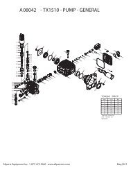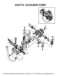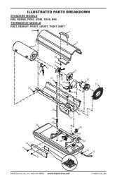
Illustrated Parts Diagram
Illustrated Parts Diagram
Illustrated Parts Diagram

You also want an ePaper? Increase the reach of your titles
YUMPU automatically turns print PDFs into web optimized ePapers that Google loves.
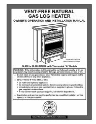
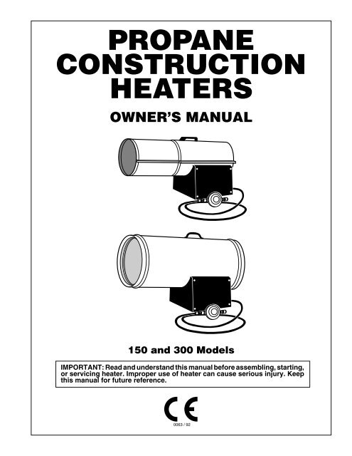
PROPANE<br />
CONSTRUCTION<br />
HEATERS<br />
OWNER’S MANUAL<br />
150 and 300 Models<br />
IMPORTANT: Read and understand this manual before assembling, starting,<br />
or servicing heater. Improper use of heater can cause serious injury. Keep<br />
this manual for future reference.<br />
0063 / 92
150 AND 300 MODELS<br />
PROPANE CONSTRUCTION HEATERS<br />
SAFETY<br />
INFORMATION<br />
FOR YOUR SAFETY: Do not<br />
use this heater in a space<br />
where gasoline or other<br />
liquids having flammable<br />
vapors are stored or used.<br />
! WARNINGS<br />
IMPORTANT: Read this owner’s<br />
manual carefully and completely<br />
before trying to assemble, operate,<br />
or service this heater. Improper<br />
use of this heater can cause<br />
serious injury or death from burns,<br />
fire, explosion, electrical shock,<br />
or carbon monoxide poisoning.<br />
Carbon Monoxide Poisoning: Early<br />
signs of carbon monoxide poisoning resemble<br />
the flu, with headaches, dizziness,<br />
and/or nausea. If you have these signs, the<br />
heater may not be working properly. Get<br />
fresh air at once! Have heater serviced.<br />
Some people are more affected by carbon<br />
monoxide than others. These include pregnant<br />
women, persons with heart or lung<br />
disease or anemia, those under the influence<br />
of alcohol, and those at high altitudes.<br />
Propane Gas: Propane gas is odorless.<br />
An odor-making agent is added to propane<br />
gas. The odor helps you detect a propane gas<br />
leak. However, the odor added to propane<br />
gas can fade. Propane gas may be present<br />
even though no odor exists.<br />
Make certain you read and understand all<br />
warnings. Keep this manual for reference. It<br />
is your guide to safe and proper operation of<br />
this heater.<br />
• Not for domestic use (inside living areas).<br />
Use heater for space heating only.<br />
• Primarily intended for temporary heating<br />
of buildings under construction, alteration,<br />
or repair.<br />
• Install and use heater with care. Follow<br />
all local ordinances and codes.<br />
• Use only in a well-vented area away from<br />
combustible materials.<br />
• Provide proper ventilation. If not, excessive<br />
levels of carbon monoxide (CO) and<br />
carbon dioxide (CO 2<br />
) will form. Provide<br />
two fresh, outside air openings for ventilation.<br />
One opening should be near the<br />
floor, the other opening near the ceiling.<br />
Each ventilation opening minimum size<br />
is as follows:<br />
150 model: 550 cm 2<br />
300 model: 875 cm 2<br />
• Never use heater where gasoline, paint<br />
thinner, or other highly flammable vapors<br />
are present. Use only in places free of<br />
flammable vapors or high dust content.<br />
• Do not use heater below ground level.<br />
Propane gas is heavier than air. If a leak<br />
occurs, propane gas will sink to the lowest<br />
possible level.<br />
• Keep heater away from strong drafts,<br />
water spray, rain, or dripping water.<br />
• Check heater for damage before each use.<br />
Do not use a damaged heater.<br />
• Use only propane gas, I3P.<br />
• Keep propane tank(s) below 38° C.<br />
• Unhook heater from propane and electrical<br />
supply before moving or when not<br />
in use.<br />
• Use only the electrical voltage and frequency<br />
specified on model plate.<br />
• Use only the hose and regulator provided<br />
with the heater.<br />
• Inspect hose before each use. If cut, worn,<br />
or damaged, replace before using heater.<br />
Use the replacement hose assembly<br />
specified in this manual.<br />
• Keep heater at least two meters from propane<br />
tank(s). Do not point heater at propane<br />
tank(s).<br />
• Minimum heater clearances from combustibles:<br />
Outlet: 3 meters Sides: 1 meter<br />
Top: 2 meters Rear: 1 meter<br />
• Locate heater on stable and level surface<br />
if heater is hot or running.<br />
• Keep children and animals away from<br />
heater.<br />
• When used with thermostat, heater may<br />
start anytime.<br />
• Never block air inlet (rear) or air outlet<br />
(front) of heater.<br />
• Never move, handle, or service a hot,<br />
operating, or plugged-in heater.<br />
• Do not alter heater. Keep heater in its<br />
original state.<br />
• Do not use heater if altered.<br />
• Never attach duct work to front or rear<br />
of heater.<br />
• Use only original replacement parts. This<br />
heater must use design-specific parts. Do<br />
not substitute or use generic parts. Improper<br />
replacement parts could cause<br />
serious or fatal injuries.<br />
2 100166
l<br />
PRODUCT<br />
IDENTIFICATION<br />
Hot Air<br />
Outlet<br />
(Front)<br />
Upper Shell<br />
Handle<br />
OWNER’S MANUAL<br />
UNPACKING<br />
1. Remove all packing items applied to<br />
heater for shipment. Keep packing<br />
items and carton for storing heater.<br />
2. Remove all items from carton.<br />
3. Check all items for shipping damage.<br />
If heater is damaged, promptly inform<br />
dealer where you bought heater.<br />
Lower Shell<br />
Fan Guard<br />
0<br />
Side Cover<br />
On/Off<br />
Switch<br />
Inlet Connector<br />
Power Cord<br />
Lamp<br />
Figure 1 - 150 Model<br />
Hose /Regulator<br />
Assembly<br />
Hot Air<br />
Outlet<br />
(Front)<br />
Handle<br />
Fan Guard<br />
Outer Shell<br />
Side Cover<br />
On/Off Switch<br />
Inlet Connector<br />
Lamp<br />
Power Cord<br />
Hose /Regulator<br />
Assembly<br />
Figure 2 - 300 Model<br />
100166<br />
3
150 AND 300 MODELS<br />
PROPANE CONSTRUCTION HEATERS<br />
THEORY OF<br />
OPERATION<br />
The Fuel System: The hose/regulator<br />
assembly attaches to the propane gas supply.<br />
The propane gas moves through the<br />
solenoid valves and out the nozzle.<br />
The Air System: The motor turns the fan.<br />
The fan pushes air into and around the<br />
combustion chamber. This air is heated and<br />
provides a stream of clean, hot air.<br />
The Ignition System: The burner control<br />
sends voltage to the ignitor. The ignitor<br />
ignites the fuel and air mixture.<br />
The Burner Control System: This system<br />
causes the heater to shut down if the<br />
flame goes out. The motor will continue to<br />
run, but no heat is produced.<br />
ATTACHING<br />
POWER CORD<br />
Follow the instructions below to attach power<br />
cord to heater.<br />
1. Remove heater side cover.<br />
2. Locate the strain relief bushing for the<br />
power cord on the heater base (see Figure<br />
4).<br />
3. Unscrew outer nut of strain relief bushing<br />
(see Figure 4). Only loosen this nut.<br />
Do not remove it.<br />
4. Insert end of power cord through strain<br />
relief bushing. Pull enough power cord<br />
into the heater base to attach wire ends<br />
to terminal board.<br />
5. Use a wrench to hold the rear hex of<br />
bushing. Tighten the outer nut of strain<br />
relief bushing until bushing firmly<br />
holds the power cord.<br />
6. Attach power cord wires to terminal<br />
board. Figure 4 shows the exact placement<br />
of each wire. Attach green wire<br />
to the earth terminal. Attach brown wire<br />
to the L 1<br />
terminal. Attach blue wire to<br />
the neutral terminal.<br />
7. Replace heater side cover.<br />
Clean<br />
Heated<br />
Air Out<br />
(Front)<br />
Combustion Chamber<br />
Ignitor<br />
Fan<br />
Figure 3 - Cross Section Operational View (300 Model Shown)<br />
Power<br />
Cord<br />
Burner Control<br />
Air For Combustion<br />
Figure 4 - Attaching Power Cord<br />
Nozzle<br />
Strain Relief<br />
Bushing<br />
Outer Nut<br />
Terminal<br />
Board<br />
Solenoid<br />
Valves<br />
Motor<br />
Air For Heating<br />
Cool<br />
Air In<br />
(Back)<br />
Power<br />
Cord<br />
Hose/Regulator<br />
Assembly<br />
Blue Wire<br />
N (neutral)<br />
L 1<br />
(line)<br />
Green Wire<br />
Brown Wire<br />
(earth)<br />
4 100166
R<br />
OWNER’S MANUAL<br />
PROPANE SUPPLY<br />
User must provide propane gas and propane<br />
tank(s).<br />
Use this heater only with a propane vapor<br />
withdrawal supply system. The amount of<br />
propane gas ready for use from propane<br />
tanks varies. Two factors decide this amount:<br />
1. The amount of propane gas in tank(s)<br />
2. The temperature of tank(s)<br />
The chart below shows the number of 45-kg<br />
tanks needed to run this heater.<br />
Do not operate this product with any tank<br />
smaller than 45 kg.<br />
Temperature<br />
(°C) At Tank Number of Tanks<br />
12° 2<br />
0° 3<br />
-10° (Use larger<br />
propane supply)<br />
Less gas is vaporized at lower temperatures.<br />
You may need a larger supply in colder<br />
weather. Your local propane gas dealer will<br />
help you select the proper supply system.<br />
INSTALLATION<br />
WARNING: Review and understand<br />
the warnings in the<br />
Safety Information Section, page<br />
2. They are needed to safely operate<br />
this heater. Follow all local<br />
codes when using this heater.<br />
WARNING: Test all gas piping<br />
and connections for leaks<br />
after installing or servicing. Never<br />
use an open flame to check for a<br />
leak. Apply a mixture of liquid<br />
soap and water to all joints.<br />
Bubbles forming show a leak.<br />
Correct all leaks at once.<br />
1. Provide propane supply system (see<br />
Propane Supply, page 5).<br />
2. Connect fuel gas connector on hose/<br />
regulator assembly to propane tank(s).<br />
Tighten firmly using wrench.<br />
IMPORTANT: Tighten regulator with<br />
black adjustment knob pointing down.<br />
Pointing adjustment knob down protects<br />
regulator from weather damage.<br />
3. Connect hose to inlet connector.<br />
Tighten firmly using a wrench.<br />
4. Open propane supply valve on propane<br />
tank(s).<br />
5. Adjust regulator between .34 and 1.34<br />
bar (see Figure 7). Note: Higher regulator<br />
setting will allow heater to produce<br />
more heat.<br />
6. Check all connections for leaks.<br />
WARNING: Never use an open<br />
flame to check for a leak. Apply a<br />
mixture of liquid soap and water<br />
to all joints. Bubbles forming show<br />
a leak. Correct all leaks at once.<br />
7. Close propane supply valve.<br />
150 Model Shown<br />
0<br />
l<br />
Supply<br />
Valve<br />
Fuel Gas<br />
Connector<br />
Hose<br />
Hose<br />
Inlet Connector<br />
Propane<br />
Tank<br />
Regulator<br />
Figure 6 - Hose and Inlet Connector<br />
I<br />
N<br />
.34 Bar<br />
E<br />
S<br />
A<br />
C<br />
E<br />
Adjustment Knob<br />
(pointing down)<br />
Figure 5 - Regulator With Adjustment<br />
Knob Pointing Down<br />
5<br />
10<br />
15<br />
20<br />
1.34 Bar<br />
5<br />
1<br />
1<br />
2<br />
5<br />
10<br />
15<br />
20<br />
Regulator<br />
Figure 7 - Adjustable Regulator Set At .34<br />
Bar<br />
100166<br />
5
150 AND 300 MODELS<br />
PROPANE CONSTRUCTION HEATERS<br />
VENTILATION<br />
WARNING: Follow the minimum<br />
fresh, outside air ventilation<br />
requirements. If proper fresh,<br />
outside air ventilation is not provided,<br />
carbon monoxide poisoning<br />
can occur. Provide proper<br />
fresh, outside air ventilation before<br />
running heater.<br />
Provide two fresh, outside air openings for<br />
ventilation. One opening should be near the<br />
floor, the other opening near the ceiling.<br />
Each ventilation opening minimum size is<br />
as follows:<br />
150 Model: 550 cm 2<br />
300 Model: 875 cm 2<br />
OPERATION<br />
WARNING: Review and understand<br />
the warnings in the<br />
Safety Information Section, page<br />
2. They are needed to safely operate<br />
this heater. Follow all local<br />
codes when using this heater.<br />
To Start Heater<br />
1. Follow all installation, ventilation and<br />
safety information.<br />
2. Locate heater on stable and level surface.<br />
Make sure strong drafts do not<br />
blow into front or rear of heater.<br />
3. Plug heater power cord into electrical<br />
source. Note: Red light indicates heater<br />
may not operate due to phase reversal.<br />
Reverse plug or check your installation<br />
to operate heater. Phase sensitivity is<br />
required by CE standards for this appliance.<br />
4. Open propane supply valve on propane<br />
tank(s).<br />
5. Make sure regulator is set between .34<br />
and 1.34 bar. Note: Higher regulator<br />
setting will allow heater to produce<br />
more heat.<br />
6. Turn on/off switch to the ON position.<br />
Heater will start within six seconds.<br />
Note: If heater does not start, turn on/<br />
off switch to the OFF position. Wait ten<br />
seconds for burner control to reset, then<br />
try again.<br />
To Stop Heater<br />
1. Tightly close propane supply valve on<br />
propane tank(s).<br />
2. Wait a few seconds. Heater will burn<br />
gas left in supply hoses.<br />
3. Turn on/off switch to the OFF position.<br />
4. Unplug heater power cord.<br />
To Restart Heater<br />
If burner control stops gas flow to heater,<br />
motor will continue to run.<br />
To restart heater:<br />
1. Turn on/off switch to the OFF position.<br />
2. Wait ten seconds, then turn on/off<br />
switch to the ON position.<br />
If heater does not restart:<br />
• Check manual valves (if any) and supply<br />
valves (on propane tank). Make sure<br />
they are open.<br />
• Check fuel level in propane tank(s). If<br />
fuel level is too low, contact local propane<br />
gas company.<br />
If heater still does not restart, contact your<br />
local service center.<br />
To Change Propane Tank(s)<br />
Change propane tank(s) in a flame-free area.<br />
Use only propane gas, I3P.<br />
1. Tightly close the propane supply<br />
valve(s) on the propane tank(s).<br />
2. Disconnect the hose/regulator assembly<br />
from the propane tank(s).<br />
3. Connect the hose/regulator assembly to<br />
the new propane tank(s). Tighten<br />
firmly.<br />
4. Check all connections for leaks.<br />
WARNING: Never use an open<br />
flame to check for a leak. Apply a<br />
mixture of liquid soap and water<br />
to all joints. Bubbles forming show<br />
a leak. Correct all leaks at once.<br />
6 100166
OWNER’S MANUAL<br />
STORAGE<br />
CAUTION: Disconnect heater<br />
from propane supply tank(s).<br />
1. Store propane tank(s) in safe manner.<br />
2. Place packing items on the heater and<br />
hose/regulator assembly. Place heater<br />
and hose/regulator assembly into heater<br />
carton.<br />
3. Store in dry, clean, and safe place. Do<br />
not store hose/regulator assembly inside<br />
heater combustion chamber.<br />
4. When taking heater out of storage, always<br />
check inside of heater. Insects and<br />
small animals may place foreign objects<br />
in heater. Keep inside of heater free from<br />
combustible and foreign objects.<br />
MAINTENANCE<br />
WARNING: Never service<br />
heater while it is plugged in, connected<br />
to propane supply, operating,<br />
or hot. Severe burns and<br />
electrical shock can occur.<br />
1. Keep heater clean. Clean heater annually<br />
or as needed to remove dust and<br />
debris. If heater is dirty or dusty, clean<br />
heater with a damp cloth.<br />
2. Inspect heater before each use. Check<br />
connections for leaks. Apply mixture<br />
of liquid soap and water to connections.<br />
Bubbles forming show a leak. Correct<br />
all leaks at once.<br />
3. Inspect hose/regulator assembly before<br />
each use. If hose is highly worn<br />
or cut, replace.<br />
4. Have heater inspected yearly by service<br />
person.<br />
5. Keep inside of heater free from combustible<br />
and foreign objects.<br />
6. Clean fan every 500 hours of operation<br />
or as needed.<br />
SERVICE<br />
PROCEDURE<br />
WARNING: Never service<br />
heater while it is plugged in, connected<br />
to propane supply, operating,<br />
or hot. Severe burns and<br />
electrical shock can occur.<br />
Cleaning Fan<br />
150 Model<br />
1. Remove upper shell of heater. Remove<br />
screws along each side of heater using<br />
5/16" nut-driver (see Figure 8). These<br />
screws attach upper and lower shells<br />
together.<br />
2. Lift or slide upper shell off.<br />
3. Remove fan guard.<br />
4. Use 1/8" Allen wrench to loosen setscrew<br />
which holds fan to motor shaft<br />
(see Figure 9).<br />
5. Slip fan off motor shaft.<br />
6. Clean fan using soft cloth moistened<br />
with kerosene or solvent.<br />
7. Dry fan thoroughly.<br />
8. Replace fan on motor shaft. Make sure<br />
set screw is touching back of flat surface<br />
on motor shaft (see Figure 10).<br />
9. Place setscrew on flat of shaft. Tighten<br />
setscrew firmly (4.5-5.6 n-m).<br />
10. Replace fan guard and upper shell.<br />
Figure 8 - Upper Shell Removal, 150 Model<br />
0<br />
l<br />
Motor shaft<br />
Figure 9 - Fan, Motor Shaft, and Setscrew<br />
Location<br />
Hub<br />
Fan<br />
Fan<br />
Setscrew<br />
Setscrew<br />
Motor Shaft<br />
Figure 10 - Fan Cross Section<br />
Continued<br />
100166<br />
7
150 AND 300 MODELS<br />
PROPANE CONSTRUCTION HEATERS<br />
SERVICE<br />
PROCEDURE<br />
Continued<br />
Cleaning Fan<br />
300 Model<br />
Clean fan every 500 hours of operation or as<br />
needed.<br />
1. Remove screws on side cover using 5/16"<br />
nut-driver.<br />
2. Remove side cover.<br />
3. Detach the four motor wires from parts<br />
under heater shell (see Figure 11). Be<br />
sure to detach only wires coming from<br />
motor. The four motor wires are:<br />
• black wire—to burner control<br />
• blue wire—to termianl board<br />
• green wire—to termianl board<br />
• brown wire—to on/off switch<br />
4. Remove fan guard screw from top rear<br />
of heater shell. Remove fan guard.<br />
5. Reach into rear of heater shell. Carefully<br />
pull motor wires through hole in<br />
bottom of shell (see Figure 12). Note:<br />
Pull wires through hole one at a time.<br />
6. Remove nuts and mounting bolts holding<br />
motor mount to shell. Use 3/8" nutdriver<br />
and 7/16" wrench (see Figure 12).<br />
Burner<br />
Control<br />
Terminal<br />
Board<br />
On/Off<br />
Switch<br />
7. Carefully pull motor and fan out of<br />
shell. IMPORTANT: Be careful not to<br />
damage fan. Do not set motor and fan<br />
down with the weight resting on fan.<br />
This could damage fan pitch.<br />
8. Turn motor and fan around. Place motor<br />
and fan into shell backwards. Note: Motor<br />
will go into shell first (see Figure 13).<br />
9. Line up rear mounting holes in shell<br />
with first hole on each side of motor<br />
mount (see Figure 13). Note: When<br />
holes are lined up, fan should be outside<br />
of shell.<br />
10. Holding mounting bolt, carefully reach<br />
through fan blades into rear of heater.<br />
Be careful not to damage fan pitch. Insert<br />
bolt through motor mount and shell.<br />
With free hand, attach nut finger tight.<br />
Repeat process for other mounting hole.<br />
11. Use 1/8" Allen wrench to loosen setscrew<br />
which holds fan to motor shaft<br />
(see Figure 14).<br />
12. Slip fan off motor shaft.<br />
13. Clean fan using soft cloth moistened<br />
with kerosene or solvent.<br />
14. Dry fan thoroughly.<br />
15. Replace fan on motor shaft. Make sure<br />
set screw is touching back of flat surface<br />
on motor shaft (see Figure 15).<br />
16. Place setscrew on flat of shaft. Tighten<br />
setscrew firmly (4.5-5.6 n-m).<br />
17. Remove two nuts and bolts securing<br />
motor mount to shell.<br />
18. Pull motor and fan from shell. Turn<br />
motor and fan around. Carefully place<br />
back in shell. Note: Fan will go into<br />
shell first.<br />
19. Line up mounting holes in shell with<br />
holes on motor mount. Replace four<br />
bolts through shell and motor mount.<br />
Insert bolts from outside of heater.<br />
Tighten nuts firmly.<br />
20. Route motor wires through hole in bottom<br />
of shell (see Figure 12).<br />
21. Connect motor wires as follows (see<br />
Figure 11):<br />
• black wire—to burner control<br />
• blue wire—to terminal board (see<br />
Wiring <strong>Diagram</strong>, page 9, for correct<br />
terminal location)<br />
• green wire—to terminal board (see<br />
Wiring <strong>Diagram</strong>, page 9, for correct<br />
terminal location)<br />
• brown wire—to on/off switch<br />
22. Replace side cover.<br />
23. Replace fan guard.<br />
Fan<br />
Motor shaft<br />
Figure 14 - Fan, Motor Shaft, and Setscrew<br />
Location<br />
Fan<br />
Setscrew<br />
Figure 11 - Location of Motor Wires<br />
Rear<br />
Mounting<br />
Hole<br />
Hub<br />
Mounting<br />
Bolts<br />
Motor<br />
Mount<br />
First<br />
Hole<br />
Motor<br />
Shaft<br />
Setscrew<br />
Figure 15 - Fan Cross Section<br />
Motor<br />
Wires<br />
Figure 12 - Location of Fan and Motor<br />
Figure 13 - Fan and Motor Turned Around<br />
8 100166
OWNER’S MANUAL<br />
SERVICE<br />
PROCEDURE<br />
Continued<br />
Ignitor<br />
Make sure gap between ignitor electrode<br />
and burner nozzle is 4.8 mm. Access ignitor<br />
electrode from inside combustion chamber.<br />
No other maintenance is needed for ignitor.<br />
If a Gas Leak Occurs<br />
WARNING: If you detect a gas<br />
leak, turn off propane supply at<br />
once. Ventilate the area. Wait until<br />
five minutes after propane odor<br />
is not present. Follow steps below<br />
to check for gas leak.<br />
WARNING: Never use an open<br />
flame to check for a leak. Apply a<br />
mixture of liquid soap and water<br />
to all joints. Bubbles forming show<br />
a leak. Correct all leaks at once.<br />
1. After turning off propane supply and<br />
ventilating area, turn heater on/off<br />
switch to the OFF position. Unplug<br />
heater power cord.<br />
2. Turn propane supply on.<br />
3. Apply a mixture of liquid soap and<br />
water to hose and connections between<br />
propane tank(s) and heater inlet.<br />
Bubbles forming show a leak.<br />
4. Turn propane supply off and ventilate<br />
the area. Repair leak.<br />
5. Wait until five minutes after propane<br />
odor is not present before restarting<br />
heater.<br />
6. If you cannot repair leak, contact you<br />
local service center.<br />
SPECIFICATIONS<br />
Model 150 300<br />
Electrical Input 220/240 volt, 50 hertz, 220/240 volt, 50 hertz,<br />
200 watts IP20 200 watts IP20<br />
Maximum Input, net 44 KW at 1.34 bar 70 KW at 1.34 bar<br />
Minimum Input, net 20 KW at .34 bar 31 KW at .34 bar<br />
Regulator Output (max./min.) 1.34 bar/.34 bar 1.34 bar/.34 bar<br />
Burner Rate 44 KW, 3400 g/hr max. 70 KW, 5400 g/hr max.<br />
20 KW, 1550 g/hr min. 31 KW, 2400 g/hr min.<br />
Supply Pressure (min.) 2 bar 2 bar<br />
Ventilation 1100 cm 2 1750 cm 2<br />
Room Size 440 cubic meters 700 cubic meters<br />
Air Delivery Class Type A Type A<br />
WIRING DIAGRAM<br />
Ignitor<br />
Orange<br />
Burner<br />
Control<br />
Green<br />
Blue<br />
Black<br />
Blue<br />
Brown<br />
White<br />
Green<br />
Figure 16 - Wiring <strong>Diagram</strong><br />
Solenoid<br />
Valve<br />
Blue<br />
Blue<br />
Connector<br />
Connector<br />
Green<br />
Blue<br />
Solenoid<br />
Valve<br />
T<br />
Thermal<br />
Switch<br />
Blue<br />
Motor<br />
Yellow<br />
Brown<br />
On/Off Switch<br />
Blue<br />
Brown<br />
Green<br />
Centrifugal<br />
Switch<br />
Terminal<br />
Board<br />
Blue<br />
Brown<br />
Green<br />
Yellow<br />
Connector<br />
Black<br />
Green<br />
White<br />
Power<br />
Cord<br />
Green<br />
Lamp<br />
150<br />
Model<br />
Only<br />
100166<br />
9
150 AND 300 MODELS<br />
PROPANE CONSTRUCTION HEATERS<br />
ILLUSTRATED<br />
PARTS<br />
BREAKDOWN<br />
150 MODEL<br />
2<br />
31<br />
1<br />
3<br />
9<br />
53<br />
56<br />
55<br />
32<br />
23<br />
24<br />
54<br />
52<br />
25<br />
47<br />
4<br />
5<br />
11<br />
18<br />
46<br />
10<br />
17<br />
37<br />
44<br />
26<br />
34<br />
33<br />
21<br />
38<br />
22<br />
12<br />
6<br />
7<br />
20<br />
29<br />
40<br />
41<br />
13<br />
15<br />
16<br />
15<br />
51<br />
35<br />
20<br />
42<br />
30<br />
14<br />
43<br />
13<br />
28<br />
45<br />
39<br />
36<br />
27<br />
19<br />
8<br />
10 100166
PARTS LIST<br />
150 MODEL<br />
OWNER’S MANUAL<br />
This list contains replaceable parts used in your heater. When ordering parts, be sure to provide the correct<br />
model and serial numbers (from the model plate), then the part number and description of the desired part.<br />
KEY PART<br />
NO. NUMBER DESCRIPTION QTY.<br />
KEY PART<br />
NO. NUMBER DESCRIPTION QTY.<br />
1 M51072-02AA Upper Shell (RM150E) 1<br />
M51072-02AB Upper Shell (BLP150E) 1<br />
079028-01AC Upper Shell (RLP150E) 1<br />
2 M15823-27 Screw, #10-16 x 1/2" 8<br />
3 099443-01 Combustion Chamber 1<br />
4 097805-01 Ignitor 1<br />
5 M10908-1 Screw, #6-32 x 1/4" 1<br />
6 M11084-39 Screw, #8 x 1/2" 1<br />
7 WLI-2BL Washer 1<br />
8 097806-02 Ignitor Cable 1<br />
9 M51108-01 Heat Shield 1<br />
10 M51153-01 Fan 1<br />
11 100298-01 Motor 1<br />
12 097776-01 Bushing 1<br />
13 097809-01 Male Fitting 2<br />
14 100301-01 Valve Bracket 1<br />
15 097803-01 Solenoid Valve 2<br />
16 097153-02 Pipe Nipple, 1/4 x 2" 1<br />
17 097905-02 Fuel Tube 1<br />
18 098425-01 Nozzle 1<br />
19 M12461-25 Screw, #10-32 x 1/4" 2<br />
20 M11084-26 Screw, #10 x 3/8" 10<br />
21 M50104-05 Bushing 1<br />
22 M50104-01 Bushing 1<br />
23 097952-07 Thermal Switch 1<br />
24 097968-01 Screw, #4-40 x 1/4" 2<br />
25 NPC-00C Nut, #4-40 2<br />
26 M51073-06AA Lower Shell (RM150E) 1<br />
M51073-06AB Lower Shell (BLP150E) 1<br />
M51073-06AC Lower Shell (RLP150E) 1<br />
27 097965-02AA Side Cover 1<br />
28 097462-01 On/Off Switch 1<br />
29 M12461-7 Screw, #6-32 x 1" 2<br />
30 099432-01 Nut, #6-32 2<br />
31 M51104-01 Handle 1<br />
32 M11084-29 Screw, #10 x 3/4" 2<br />
33 097964-03AA Fan Guard 1<br />
34 M51074-01 Motor Mounting Bracket 1<br />
35 M50400 Strain Relief Bushing 1<br />
36 097545-01 Power Cord 1<br />
37 M50631 Rubber Bumper 2<br />
38 NTC-4C Lock Nut, 1/4-20 2<br />
39 099157-01 Aluminum Rivet 1<br />
40 099125-06 Terminal Board 1<br />
41 097966-08AA Base 1<br />
42 M51605-04 Burner Control 1<br />
43 M10908-27 Screw, #10-32 x 1/2" 2<br />
44 M11271-8 U-Nut, #10 8<br />
45 100371-01 Lamp 1<br />
46 100299-01 Rear Plate 1<br />
47 097849-02 Burner Assembly 1<br />
48 M16841-62 Wire Assembly, Green 1<br />
49 M16841-55 Wire Assembly, Green 2<br />
50 097951-04 Wire Assembly, Brown 1<br />
51 M11084-37 Screw, #8 x 1/4" 2<br />
52 098428-01 Clip 1<br />
53 098406-01 Rivet 3<br />
54 NPC-4C Nut, 1/4-20 3<br />
55 WLI-4C Lock Washer 3<br />
56 098434-01 Spacer 3<br />
PARTS AVAILABLE – NOT SHOWN<br />
099596-05 Tradename Decal (RM150E) 2<br />
097940-03 Tradename Decal (BLP150E) 2<br />
097941-11 Tradename Decal (RLP150E) 2<br />
100181-01 General Information Decal 1<br />
100462-01 Operation Decal 1<br />
100372-01 Lamp Decal 1<br />
100168-01 Wiring <strong>Diagram</strong> Decal 1<br />
097953-02 Regulator/Hose Assembly 1<br />
49<br />
49<br />
Ignitor<br />
Orange<br />
Burner<br />
Control<br />
Green<br />
Blue<br />
Black<br />
Blue<br />
Brown<br />
White<br />
Green<br />
Solenoid<br />
Valve<br />
Blue<br />
Blue<br />
Connector<br />
Connector<br />
Green<br />
Blue<br />
Solenoid<br />
Valve<br />
T<br />
Thermal<br />
Switch<br />
Blue<br />
Motor<br />
Yellow<br />
Centrifugal<br />
Switch<br />
Yellow<br />
Connector<br />
Black<br />
Brown<br />
On/Off Switch<br />
White<br />
Terminal<br />
Board Lamp<br />
Blue Blue<br />
Brown<br />
Brown<br />
Green<br />
Green<br />
Power<br />
Cord<br />
Green<br />
Green<br />
150<br />
Model<br />
Only<br />
50<br />
48<br />
100166<br />
11
150 AND 300 MODELS<br />
PROPANE CONSTRUCTION HEATERS<br />
ILLUSTRATED<br />
PARTS<br />
BREAKDOWN<br />
300 MODEL<br />
2<br />
8<br />
4<br />
43<br />
1<br />
6<br />
7<br />
3<br />
5<br />
55<br />
10<br />
56<br />
44<br />
9<br />
43<br />
13<br />
53<br />
12<br />
43<br />
11<br />
52 51<br />
46<br />
15<br />
18<br />
46 47 18<br />
23<br />
16 45<br />
20<br />
21<br />
14<br />
43<br />
42<br />
27<br />
34<br />
37<br />
31<br />
32<br />
38<br />
30<br />
25<br />
54<br />
31<br />
33<br />
36<br />
28<br />
29<br />
22<br />
24<br />
39<br />
35<br />
26<br />
41<br />
40<br />
17<br />
44<br />
17<br />
19<br />
12 100166
PARTS LIST<br />
300 MODEL<br />
OWNER’S MANUAL<br />
This list contains replaceable parts used in your heater. When ordering parts, be sure to provide the correct<br />
model and serial numbers (from the model plate), then the part number and description of the desired part.<br />
KEY PART<br />
NO. NUMBER DESCRIPTION QTY.<br />
KEY PART<br />
NO. NUMBER DESCRIPTION QTY.<br />
1 097963-01AA Outer Shell (RM300E) 1<br />
097963-01AB Outer Shell (BLP300E) 1<br />
097963-01AC Outer Shell (RLP300E) 1<br />
2 097847-01 Combustion Chamber 1<br />
3 097952-06 Thermal Switch 1<br />
4 097968-01 Screw, #4-40 x 1/4" 2<br />
5 NPC-00C Nut, #4-40 2<br />
6 097917-01 Handle 1<br />
7 097918-01 Handle Cleat 2<br />
8 M12461-26 Screw, #10-32 x 3/8" 4<br />
9 NTF-3C Torque Nut, #10-32 4<br />
10 097930-01 Bushing 1<br />
11 097848-01 Rear Plate 1<br />
12 097805-01 Ignitor 1<br />
13 M10908-1 Screw, #6-32 x 1/4" 1<br />
14 097849-01 Burner Assembly 1<br />
15 097811-01 Fan 1<br />
16 100144-01 Motor 1<br />
17 NTC-4C Torque Nut, 1/4-20 8<br />
18 M12461-62 Screw, 1/4-20 x 3/8" 8<br />
19 097829-02 Motor Mount 1<br />
20 097964-01AA Fan Guard 1<br />
21 100311-01 Fuel Tube 1<br />
22 100146-01 Female Elbow 1<br />
23 099679-02 Nozzle 1<br />
24 097966-05AA Base 1<br />
25 099125-06 Terminal Board 1<br />
26 097462-01 On/Off Switch 1<br />
27 M51605-04 Burner Control 1<br />
28 097806-02 Ignitor Cable 1<br />
29 097809-01 Male Fitting 1<br />
30 100301-02 Valve Bracket 1<br />
31 097803-01 Solenoid Valve 2<br />
32 097153-02 Pipe Nipple 1<br />
33 M12461-25 Screw, #10-32 x 1/4" 2<br />
34 098825-01 Male Compression Elbow 1<br />
35 099157-01 Aluminum Rivet 1<br />
36 M10908-27 Screw, #10-32 x 1/2" 2<br />
37 M12461-7 Screw, #6-32 x 1" 2<br />
38 099432-01 Nut, #6-32 2<br />
39 100371-01 Lamp 1<br />
40 097545-01 Power Cord 1<br />
41 M50400 Strain Relief Bushing 1<br />
42 097965-01AA Side Cover 1<br />
43 M11084-26 Screw, #10-16 x 3/8" 19<br />
44 M50104-02 Bushing 3<br />
45 100373-01 Clamp 1<br />
46 M11084-39 Screw, #8-18 x 1/2" 2<br />
47 WLI-2BL Washer 1<br />
48 M16841-62 Wire Assembly, Green 1<br />
49 M16841-55 Wire Assembly, Green 2<br />
50 097951-04 Wire Assembly, Brown 1<br />
51 NPC-4C Nut, 1/4-20 3<br />
52 WLI-4C Lock Washer 3<br />
53 097839-01 Spacer 3<br />
54 M11084-37 Screw, #8 x 1/4" 2<br />
55 097916-01 Baffle 1<br />
56 099202-02 Rivet 3<br />
PARTS AVAILABLE – NOT SHOWN<br />
099596-06 Tradename Decal (RM300E) 2<br />
097895-03 Tradename Decal (BLP300E) 2<br />
097941-12 Tradename Decal (RLP300E) 2<br />
100180-01 General Information Decal 1<br />
100462-01 Operation Decal 1<br />
100372-01 Lamp Decal 1<br />
100168-01 Wiring <strong>Diagram</strong> Decal 1<br />
097953-02 Regulator/Hose Assembly 1<br />
49<br />
49<br />
Ignitor<br />
Orange<br />
Burner<br />
Control<br />
Green<br />
Blue<br />
Black<br />
Blue<br />
Brown<br />
Solenoid<br />
Valve<br />
Blue<br />
Blue<br />
Connector<br />
Connector<br />
Green<br />
Blue<br />
Solenoid<br />
Valve<br />
T<br />
Thermal<br />
Switch<br />
Blue<br />
Motor<br />
Yellow<br />
Brown<br />
On/Off Switch<br />
Blue<br />
Brown<br />
Green<br />
Centrifugal<br />
Switch<br />
Terminal<br />
Board<br />
Blue<br />
Brown<br />
Green<br />
Yellow<br />
Connector<br />
Black<br />
White<br />
Lamp<br />
Power<br />
Cord<br />
150<br />
Model<br />
Only<br />
50<br />
White<br />
Green<br />
Green<br />
Green<br />
48<br />
100166<br />
13
WARRANTY AND REPAIR SERVICE<br />
KEEP THIS WARRANTY<br />
LIMITED WARRANTY<br />
DESA International warrants this product and any parts thereof, to be free from defects in materials and workmanship for<br />
six (6) months from the date of first purchase when operated and maintained in accordance with instructions. This warranty<br />
is extended only to the original retail purchaser, when proof of purchase is provided.<br />
This warranty covers only the cost of parts required to restore the product to proper operating condition. Transportation and<br />
incidental costs associated with warranty parts are not reimbursable under this warranty.<br />
This warranty does not cover defects resulting from misuse, abuse, negligence, accidents, lack of proper maintenance,<br />
normal wear, alteration, modification, tampering, contaminated fuels, repair using improper parts, or repair by anyone other<br />
than an authorized dealer or service center. Routine maintenance is the responsibility of the owner.<br />
This express warranty is given in lieu of any other warranty either expressed or implied, including warranties of<br />
merchantability and fitness for a particular purpose.<br />
DESA International assumes no responsibility for indirect, incidental or consequential damages.<br />
We reserve the right to amend these specifications at any time without notice. The only warranty applicable is our<br />
standard written warranty. We make no other warranty, expressed or implied.<br />
Model<br />
Serial No.<br />
Date of Purchase<br />
DESA<br />
INTERNATIONAL<br />
2701 Industrial Drive<br />
P.O. Box 90004<br />
Bowling Green, KY 42102-9004<br />
U.S.A.<br />
For information, write: DESA International, P.O. Box 90004<br />
Bowling Green, Kentucky 42102-9004 U.S.A.<br />
ATTN: Customer Service Department<br />
When writing, always include model number and serial number.