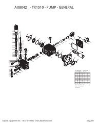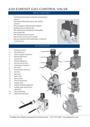
Illustrated Parts Diagram
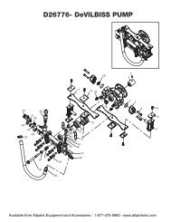
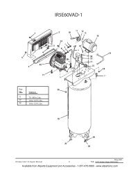
Illustrated Parts Diagram
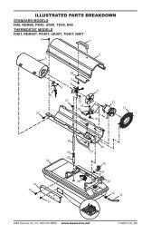
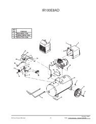
Illustrated Parts Diagram

You also want an ePaper? Increase the reach of your titles
YUMPU automatically turns print PDFs into web optimized ePapers that Google loves.
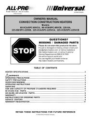
150 AND 300 MODELS<br />
PROPANE CONSTRUCTION HEATERS<br />
SERVICE<br />
PROCEDURE<br />
Continued<br />
Cleaning Fan<br />
300 Model<br />
Clean fan every 500 hours of operation or as<br />
needed.<br />
1. Remove screws on side cover using 5/16"<br />
nut-driver.<br />
2. Remove side cover.<br />
3. Detach the four motor wires from parts<br />
under heater shell (see Figure 11). Be<br />
sure to detach only wires coming from<br />
motor. The four motor wires are:<br />
• black wire—to burner control<br />
• blue wire—to termianl board<br />
• green wire—to termianl board<br />
• brown wire—to on/off switch<br />
4. Remove fan guard screw from top rear<br />
of heater shell. Remove fan guard.<br />
5. Reach into rear of heater shell. Carefully<br />
pull motor wires through hole in<br />
bottom of shell (see Figure 12). Note:<br />
Pull wires through hole one at a time.<br />
6. Remove nuts and mounting bolts holding<br />
motor mount to shell. Use 3/8" nutdriver<br />
and 7/16" wrench (see Figure 12).<br />
Burner<br />
Control<br />
Terminal<br />
Board<br />
On/Off<br />
Switch<br />
7. Carefully pull motor and fan out of<br />
shell. IMPORTANT: Be careful not to<br />
damage fan. Do not set motor and fan<br />
down with the weight resting on fan.<br />
This could damage fan pitch.<br />
8. Turn motor and fan around. Place motor<br />
and fan into shell backwards. Note: Motor<br />
will go into shell first (see Figure 13).<br />
9. Line up rear mounting holes in shell<br />
with first hole on each side of motor<br />
mount (see Figure 13). Note: When<br />
holes are lined up, fan should be outside<br />
of shell.<br />
10. Holding mounting bolt, carefully reach<br />
through fan blades into rear of heater.<br />
Be careful not to damage fan pitch. Insert<br />
bolt through motor mount and shell.<br />
With free hand, attach nut finger tight.<br />
Repeat process for other mounting hole.<br />
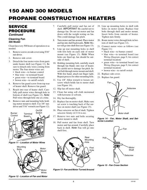
11. Use 1/8" Allen wrench to loosen setscrew<br />
which holds fan to motor shaft<br />
(see Figure 14).<br />
12. Slip fan off motor shaft.<br />
13. Clean fan using soft cloth moistened<br />
with kerosene or solvent.<br />
14. Dry fan thoroughly.<br />
15. Replace fan on motor shaft. Make sure<br />
set screw is touching back of flat surface<br />
on motor shaft (see Figure 15).<br />
16. Place setscrew on flat of shaft. Tighten<br />
setscrew firmly (4.5-5.6 n-m).<br />
17. Remove two nuts and bolts securing<br />
motor mount to shell.<br />
18. Pull motor and fan from shell. Turn<br />
motor and fan around. Carefully place<br />
back in shell. Note: Fan will go into<br />
shell first.<br />
19. Line up mounting holes in shell with<br />
holes on motor mount. Replace four<br />
bolts through shell and motor mount.<br />
Insert bolts from outside of heater.<br />
Tighten nuts firmly.<br />
20. Route motor wires through hole in bottom<br />
of shell (see Figure 12).<br />
21. Connect motor wires as follows (see<br />
Figure 11):<br />
• black wire—to burner control<br />
• blue wire—to terminal board (see<br />
Wiring <strong>Diagram</strong>, page 9, for correct<br />
terminal location)<br />
• green wire—to terminal board (see<br />
Wiring <strong>Diagram</strong>, page 9, for correct<br />
terminal location)<br />
• brown wire—to on/off switch<br />
22. Replace side cover.<br />
23. Replace fan guard.<br />
Fan<br />
Motor shaft<br />
Figure 14 - Fan, Motor Shaft, and Setscrew<br />
Location<br />
Fan<br />
Setscrew<br />
Figure 11 - Location of Motor Wires<br />
Rear<br />
Mounting<br />
Hole<br />
Hub<br />
Mounting<br />
Bolts<br />
Motor<br />
Mount<br />
First<br />
Hole<br />
Motor<br />
Shaft<br />
Setscrew<br />
Figure 15 - Fan Cross Section<br />
Motor<br />
Wires<br />
Figure 12 - Location of Fan and Motor<br />
Figure 13 - Fan and Motor Turned Around<br />
8 100166