Illustrated Parts Diagram
Illustrated Parts Diagram
Illustrated Parts Diagram

Create successful ePaper yourself
Turn your PDF publications into a flip-book with our unique Google optimized e-Paper software.
PROPANE<br />
CONSTRUCTION<br />
HEATERS<br />
OWNER’S MANUAL<br />
150 and 300 Models<br />
IMPORTANT: Read and understand this manual before assembling, starting,<br />
or servicing heater. Improper use of heater can cause serious injury. Keep<br />
this manual for future reference.<br />
0063 / 92
150 AND 300 MODELS<br />
PROPANE CONSTRUCTION HEATERS<br />
SAFETY<br />
INFORMATION<br />
FOR YOUR SAFETY: Do not<br />
use this heater in a space<br />
where gasoline or other<br />
liquids having flammable<br />
vapors are stored or used.<br />
! WARNINGS<br />
IMPORTANT: Read this owner’s<br />
manual carefully and completely<br />
before trying to assemble, operate,<br />
or service this heater. Improper<br />
use of this heater can cause<br />
serious injury or death from burns,<br />
fire, explosion, electrical shock,<br />
or carbon monoxide poisoning.<br />
Carbon Monoxide Poisoning: Early<br />
signs of carbon monoxide poisoning resemble<br />
the flu, with headaches, dizziness,<br />
and/or nausea. If you have these signs, the<br />
heater may not be working properly. Get<br />
fresh air at once! Have heater serviced.<br />
Some people are more affected by carbon<br />
monoxide than others. These include pregnant<br />
women, persons with heart or lung<br />
disease or anemia, those under the influence<br />
of alcohol, and those at high altitudes.<br />
Propane Gas: Propane gas is odorless.<br />
An odor-making agent is added to propane<br />
gas. The odor helps you detect a propane gas<br />
leak. However, the odor added to propane<br />
gas can fade. Propane gas may be present<br />
even though no odor exists.<br />
Make certain you read and understand all<br />
warnings. Keep this manual for reference. It<br />
is your guide to safe and proper operation of<br />
this heater.<br />
• Not for domestic use (inside living areas).<br />
Use heater for space heating only.<br />
• Primarily intended for temporary heating<br />
of buildings under construction, alteration,<br />
or repair.<br />
• Install and use heater with care. Follow<br />
all local ordinances and codes.<br />
• Use only in a well-vented area away from<br />
combustible materials.<br />
• Provide proper ventilation. If not, excessive<br />
levels of carbon monoxide (CO) and<br />
carbon dioxide (CO 2<br />
) will form. Provide<br />
two fresh, outside air openings for ventilation.<br />
One opening should be near the<br />
floor, the other opening near the ceiling.<br />
Each ventilation opening minimum size<br />
is as follows:<br />
150 model: 550 cm 2<br />
300 model: 875 cm 2<br />
• Never use heater where gasoline, paint<br />
thinner, or other highly flammable vapors<br />
are present. Use only in places free of<br />
flammable vapors or high dust content.<br />
• Do not use heater below ground level.<br />
Propane gas is heavier than air. If a leak<br />
occurs, propane gas will sink to the lowest<br />
possible level.<br />
• Keep heater away from strong drafts,<br />
water spray, rain, or dripping water.<br />
• Check heater for damage before each use.<br />
Do not use a damaged heater.<br />
• Use only propane gas, I3P.<br />
• Keep propane tank(s) below 38° C.<br />
• Unhook heater from propane and electrical<br />
supply before moving or when not<br />
in use.<br />
• Use only the electrical voltage and frequency<br />
specified on model plate.<br />
• Use only the hose and regulator provided<br />
with the heater.<br />
• Inspect hose before each use. If cut, worn,<br />
or damaged, replace before using heater.<br />
Use the replacement hose assembly<br />
specified in this manual.<br />
• Keep heater at least two meters from propane<br />
tank(s). Do not point heater at propane<br />
tank(s).<br />
• Minimum heater clearances from combustibles:<br />
Outlet: 3 meters Sides: 1 meter<br />
Top: 2 meters Rear: 1 meter<br />
• Locate heater on stable and level surface<br />
if heater is hot or running.<br />
• Keep children and animals away from<br />
heater.<br />
• When used with thermostat, heater may<br />
start anytime.<br />
• Never block air inlet (rear) or air outlet<br />
(front) of heater.<br />
• Never move, handle, or service a hot,<br />
operating, or plugged-in heater.<br />
• Do not alter heater. Keep heater in its<br />
original state.<br />
• Do not use heater if altered.<br />
• Never attach duct work to front or rear<br />
of heater.<br />
• Use only original replacement parts. This<br />
heater must use design-specific parts. Do<br />
not substitute or use generic parts. Improper<br />
replacement parts could cause<br />
serious or fatal injuries.<br />
2 100166
l<br />
PRODUCT<br />
IDENTIFICATION<br />
Hot Air<br />
Outlet<br />
(Front)<br />
Upper Shell<br />
Handle<br />
OWNER’S MANUAL<br />
UNPACKING<br />
1. Remove all packing items applied to<br />
heater for shipment. Keep packing<br />
items and carton for storing heater.<br />
2. Remove all items from carton.<br />
3. Check all items for shipping damage.<br />
If heater is damaged, promptly inform<br />
dealer where you bought heater.<br />
Lower Shell<br />
Fan Guard<br />
0<br />
Side Cover<br />
On/Off<br />
Switch<br />
Inlet Connector<br />
Power Cord<br />
Lamp<br />
Figure 1 - 150 Model<br />
Hose /Regulator<br />
Assembly<br />
Hot Air<br />
Outlet<br />
(Front)<br />
Handle<br />
Fan Guard<br />
Outer Shell<br />
Side Cover<br />
On/Off Switch<br />
Inlet Connector<br />
Lamp<br />
Power Cord<br />
Hose /Regulator<br />
Assembly<br />
Figure 2 - 300 Model<br />
100166<br />
3
150 AND 300 MODELS<br />
PROPANE CONSTRUCTION HEATERS<br />
THEORY OF<br />
OPERATION<br />
The Fuel System: The hose/regulator<br />
assembly attaches to the propane gas supply.<br />
The propane gas moves through the<br />
solenoid valves and out the nozzle.<br />
The Air System: The motor turns the fan.<br />
The fan pushes air into and around the<br />
combustion chamber. This air is heated and<br />
provides a stream of clean, hot air.<br />
The Ignition System: The burner control<br />
sends voltage to the ignitor. The ignitor<br />
ignites the fuel and air mixture.<br />
The Burner Control System: This system<br />
causes the heater to shut down if the<br />
flame goes out. The motor will continue to<br />
run, but no heat is produced.<br />
ATTACHING<br />
POWER CORD<br />
Follow the instructions below to attach power<br />
cord to heater.<br />
1. Remove heater side cover.<br />
2. Locate the strain relief bushing for the<br />
power cord on the heater base (see Figure<br />
4).<br />
3. Unscrew outer nut of strain relief bushing<br />
(see Figure 4). Only loosen this nut.<br />
Do not remove it.<br />
4. Insert end of power cord through strain<br />
relief bushing. Pull enough power cord<br />
into the heater base to attach wire ends<br />
to terminal board.<br />
5. Use a wrench to hold the rear hex of<br />
bushing. Tighten the outer nut of strain<br />
relief bushing until bushing firmly<br />
holds the power cord.<br />
6. Attach power cord wires to terminal<br />
board. Figure 4 shows the exact placement<br />
of each wire. Attach green wire<br />
to the earth terminal. Attach brown wire<br />
to the L 1<br />
terminal. Attach blue wire to<br />
the neutral terminal.<br />
7. Replace heater side cover.<br />
Clean<br />
Heated<br />
Air Out<br />
(Front)<br />
Combustion Chamber<br />
Ignitor<br />
Fan<br />
Figure 3 - Cross Section Operational View (300 Model Shown)<br />
Power<br />
Cord<br />
Burner Control<br />
Air For Combustion<br />
Figure 4 - Attaching Power Cord<br />
Nozzle<br />
Strain Relief<br />
Bushing<br />
Outer Nut<br />
Terminal<br />
Board<br />
Solenoid<br />
Valves<br />
Motor<br />
Air For Heating<br />
Cool<br />
Air In<br />
(Back)<br />
Power<br />
Cord<br />
Hose/Regulator<br />
Assembly<br />
Blue Wire<br />
N (neutral)<br />
L 1<br />
(line)<br />
Green Wire<br />
Brown Wire<br />
(earth)<br />
4 100166
R<br />
OWNER’S MANUAL<br />
PROPANE SUPPLY<br />
User must provide propane gas and propane<br />
tank(s).<br />
Use this heater only with a propane vapor<br />
withdrawal supply system. The amount of<br />
propane gas ready for use from propane<br />
tanks varies. Two factors decide this amount:<br />
1. The amount of propane gas in tank(s)<br />
2. The temperature of tank(s)<br />
The chart below shows the number of 45-kg<br />
tanks needed to run this heater.<br />
Do not operate this product with any tank<br />
smaller than 45 kg.<br />
Temperature<br />
(°C) At Tank Number of Tanks<br />
12° 2<br />
0° 3<br />
-10° (Use larger<br />
propane supply)<br />
Less gas is vaporized at lower temperatures.<br />
You may need a larger supply in colder<br />
weather. Your local propane gas dealer will<br />
help you select the proper supply system.<br />
INSTALLATION<br />
WARNING: Review and understand<br />
the warnings in the<br />
Safety Information Section, page<br />
2. They are needed to safely operate<br />
this heater. Follow all local<br />
codes when using this heater.<br />
WARNING: Test all gas piping<br />
and connections for leaks<br />
after installing or servicing. Never<br />
use an open flame to check for a<br />
leak. Apply a mixture of liquid<br />
soap and water to all joints.<br />
Bubbles forming show a leak.<br />
Correct all leaks at once.<br />
1. Provide propane supply system (see<br />
Propane Supply, page 5).<br />
2. Connect fuel gas connector on hose/<br />
regulator assembly to propane tank(s).<br />
Tighten firmly using wrench.<br />
IMPORTANT: Tighten regulator with<br />
black adjustment knob pointing down.<br />
Pointing adjustment knob down protects<br />
regulator from weather damage.<br />
3. Connect hose to inlet connector.<br />
Tighten firmly using a wrench.<br />
4. Open propane supply valve on propane<br />
tank(s).<br />
5. Adjust regulator between .34 and 1.34<br />
bar (see Figure 7). Note: Higher regulator<br />
setting will allow heater to produce<br />
more heat.<br />
6. Check all connections for leaks.<br />
WARNING: Never use an open<br />
flame to check for a leak. Apply a<br />
mixture of liquid soap and water<br />
to all joints. Bubbles forming show<br />
a leak. Correct all leaks at once.<br />
7. Close propane supply valve.<br />
150 Model Shown<br />
0<br />
l<br />
Supply<br />
Valve<br />
Fuel Gas<br />
Connector<br />
Hose<br />
Hose<br />
Inlet Connector<br />
Propane<br />
Tank<br />
Regulator<br />
Figure 6 - Hose and Inlet Connector<br />
I<br />
N<br />
.34 Bar<br />
E<br />
S<br />
A<br />
C<br />
E<br />
Adjustment Knob<br />
(pointing down)<br />
Figure 5 - Regulator With Adjustment<br />
Knob Pointing Down<br />
5<br />
10<br />
15<br />
20<br />
1.34 Bar<br />
5<br />
1<br />
1<br />
2<br />
5<br />
10<br />
15<br />
20<br />
Regulator<br />
Figure 7 - Adjustable Regulator Set At .34<br />
Bar<br />
100166<br />
5
150 AND 300 MODELS<br />
PROPANE CONSTRUCTION HEATERS<br />
VENTILATION<br />
WARNING: Follow the minimum<br />
fresh, outside air ventilation<br />
requirements. If proper fresh,<br />
outside air ventilation is not provided,<br />
carbon monoxide poisoning<br />
can occur. Provide proper<br />
fresh, outside air ventilation before<br />
running heater.<br />
Provide two fresh, outside air openings for<br />
ventilation. One opening should be near the<br />
floor, the other opening near the ceiling.<br />
Each ventilation opening minimum size is<br />
as follows:<br />
150 Model: 550 cm 2<br />
300 Model: 875 cm 2<br />
OPERATION<br />
WARNING: Review and understand<br />
the warnings in the<br />
Safety Information Section, page<br />
2. They are needed to safely operate<br />
this heater. Follow all local<br />
codes when using this heater.<br />
To Start Heater<br />
1. Follow all installation, ventilation and<br />
safety information.<br />
2. Locate heater on stable and level surface.<br />
Make sure strong drafts do not<br />
blow into front or rear of heater.<br />
3. Plug heater power cord into electrical<br />
source. Note: Red light indicates heater<br />
may not operate due to phase reversal.<br />
Reverse plug or check your installation<br />
to operate heater. Phase sensitivity is<br />
required by CE standards for this appliance.<br />
4. Open propane supply valve on propane<br />
tank(s).<br />
5. Make sure regulator is set between .34<br />
and 1.34 bar. Note: Higher regulator<br />
setting will allow heater to produce<br />
more heat.<br />
6. Turn on/off switch to the ON position.<br />
Heater will start within six seconds.<br />
Note: If heater does not start, turn on/<br />
off switch to the OFF position. Wait ten<br />
seconds for burner control to reset, then<br />
try again.<br />
To Stop Heater<br />
1. Tightly close propane supply valve on<br />
propane tank(s).<br />
2. Wait a few seconds. Heater will burn<br />
gas left in supply hoses.<br />
3. Turn on/off switch to the OFF position.<br />
4. Unplug heater power cord.<br />
To Restart Heater<br />
If burner control stops gas flow to heater,<br />
motor will continue to run.<br />
To restart heater:<br />
1. Turn on/off switch to the OFF position.<br />
2. Wait ten seconds, then turn on/off<br />
switch to the ON position.<br />
If heater does not restart:<br />
• Check manual valves (if any) and supply<br />
valves (on propane tank). Make sure<br />
they are open.<br />
• Check fuel level in propane tank(s). If<br />
fuel level is too low, contact local propane<br />
gas company.<br />
If heater still does not restart, contact your<br />
local service center.<br />
To Change Propane Tank(s)<br />
Change propane tank(s) in a flame-free area.<br />
Use only propane gas, I3P.<br />
1. Tightly close the propane supply<br />
valve(s) on the propane tank(s).<br />
2. Disconnect the hose/regulator assembly<br />
from the propane tank(s).<br />
3. Connect the hose/regulator assembly to<br />
the new propane tank(s). Tighten<br />
firmly.<br />
4. Check all connections for leaks.<br />
WARNING: Never use an open<br />
flame to check for a leak. Apply a<br />
mixture of liquid soap and water<br />
to all joints. Bubbles forming show<br />
a leak. Correct all leaks at once.<br />
6 100166
OWNER’S MANUAL<br />
STORAGE<br />
CAUTION: Disconnect heater<br />
from propane supply tank(s).<br />
1. Store propane tank(s) in safe manner.<br />
2. Place packing items on the heater and<br />
hose/regulator assembly. Place heater<br />
and hose/regulator assembly into heater<br />
carton.<br />
3. Store in dry, clean, and safe place. Do<br />
not store hose/regulator assembly inside<br />
heater combustion chamber.<br />
4. When taking heater out of storage, always<br />
check inside of heater. Insects and<br />
small animals may place foreign objects<br />
in heater. Keep inside of heater free from<br />
combustible and foreign objects.<br />
MAINTENANCE<br />
WARNING: Never service<br />
heater while it is plugged in, connected<br />
to propane supply, operating,<br />
or hot. Severe burns and<br />
electrical shock can occur.<br />
1. Keep heater clean. Clean heater annually<br />
or as needed to remove dust and<br />
debris. If heater is dirty or dusty, clean<br />
heater with a damp cloth.<br />
2. Inspect heater before each use. Check<br />
connections for leaks. Apply mixture<br />
of liquid soap and water to connections.<br />
Bubbles forming show a leak. Correct<br />
all leaks at once.<br />
3. Inspect hose/regulator assembly before<br />
each use. If hose is highly worn<br />
or cut, replace.<br />
4. Have heater inspected yearly by service<br />
person.<br />
5. Keep inside of heater free from combustible<br />
and foreign objects.<br />
6. Clean fan every 500 hours of operation<br />
or as needed.<br />
SERVICE<br />
PROCEDURE<br />
WARNING: Never service<br />
heater while it is plugged in, connected<br />
to propane supply, operating,<br />
or hot. Severe burns and<br />
electrical shock can occur.<br />
Cleaning Fan<br />
150 Model<br />
1. Remove upper shell of heater. Remove<br />
screws along each side of heater using<br />
5/16" nut-driver (see Figure 8). These<br />
screws attach upper and lower shells<br />
together.<br />
2. Lift or slide upper shell off.<br />
3. Remove fan guard.<br />
4. Use 1/8" Allen wrench to loosen setscrew<br />
which holds fan to motor shaft<br />
(see Figure 9).<br />
5. Slip fan off motor shaft.<br />
6. Clean fan using soft cloth moistened<br />
with kerosene or solvent.<br />
7. Dry fan thoroughly.<br />
8. Replace fan on motor shaft. Make sure<br />
set screw is touching back of flat surface<br />
on motor shaft (see Figure 10).<br />
9. Place setscrew on flat of shaft. Tighten<br />
setscrew firmly (4.5-5.6 n-m).<br />
10. Replace fan guard and upper shell.<br />
Figure 8 - Upper Shell Removal, 150 Model<br />
0<br />
l<br />
Motor shaft<br />
Figure 9 - Fan, Motor Shaft, and Setscrew<br />
Location<br />
Hub<br />
Fan<br />
Fan<br />
Setscrew<br />
Setscrew<br />
Motor Shaft<br />
Figure 10 - Fan Cross Section<br />
Continued<br />
100166<br />
7
150 AND 300 MODELS<br />
PROPANE CONSTRUCTION HEATERS<br />
SERVICE<br />
PROCEDURE<br />
Continued<br />
Cleaning Fan<br />
300 Model<br />
Clean fan every 500 hours of operation or as<br />
needed.<br />
1. Remove screws on side cover using 5/16"<br />
nut-driver.<br />
2. Remove side cover.<br />
3. Detach the four motor wires from parts<br />
under heater shell (see Figure 11). Be<br />
sure to detach only wires coming from<br />
motor. The four motor wires are:<br />
• black wire—to burner control<br />
• blue wire—to termianl board<br />
• green wire—to termianl board<br />
• brown wire—to on/off switch<br />
4. Remove fan guard screw from top rear<br />
of heater shell. Remove fan guard.<br />
5. Reach into rear of heater shell. Carefully<br />
pull motor wires through hole in<br />
bottom of shell (see Figure 12). Note:<br />
Pull wires through hole one at a time.<br />
6. Remove nuts and mounting bolts holding<br />
motor mount to shell. Use 3/8" nutdriver<br />
and 7/16" wrench (see Figure 12).<br />
Burner<br />
Control<br />
Terminal<br />
Board<br />
On/Off<br />
Switch<br />
7. Carefully pull motor and fan out of<br />
shell. IMPORTANT: Be careful not to<br />
damage fan. Do not set motor and fan<br />
down with the weight resting on fan.<br />
This could damage fan pitch.<br />
8. Turn motor and fan around. Place motor<br />
and fan into shell backwards. Note: Motor<br />
will go into shell first (see Figure 13).<br />
9. Line up rear mounting holes in shell<br />
with first hole on each side of motor<br />
mount (see Figure 13). Note: When<br />
holes are lined up, fan should be outside<br />
of shell.<br />
10. Holding mounting bolt, carefully reach<br />
through fan blades into rear of heater.<br />
Be careful not to damage fan pitch. Insert<br />
bolt through motor mount and shell.<br />
With free hand, attach nut finger tight.<br />
Repeat process for other mounting hole.<br />
11. Use 1/8" Allen wrench to loosen setscrew<br />
which holds fan to motor shaft<br />
(see Figure 14).<br />
12. Slip fan off motor shaft.<br />
13. Clean fan using soft cloth moistened<br />
with kerosene or solvent.<br />
14. Dry fan thoroughly.<br />
15. Replace fan on motor shaft. Make sure<br />
set screw is touching back of flat surface<br />
on motor shaft (see Figure 15).<br />
16. Place setscrew on flat of shaft. Tighten<br />
setscrew firmly (4.5-5.6 n-m).<br />
17. Remove two nuts and bolts securing<br />
motor mount to shell.<br />
18. Pull motor and fan from shell. Turn<br />
motor and fan around. Carefully place<br />
back in shell. Note: Fan will go into<br />
shell first.<br />
19. Line up mounting holes in shell with<br />
holes on motor mount. Replace four<br />
bolts through shell and motor mount.<br />
Insert bolts from outside of heater.<br />
Tighten nuts firmly.<br />
20. Route motor wires through hole in bottom<br />
of shell (see Figure 12).<br />
21. Connect motor wires as follows (see<br />
Figure 11):<br />
• black wire—to burner control<br />
• blue wire—to terminal board (see<br />
Wiring <strong>Diagram</strong>, page 9, for correct<br />
terminal location)<br />
• green wire—to terminal board (see<br />
Wiring <strong>Diagram</strong>, page 9, for correct<br />
terminal location)<br />
• brown wire—to on/off switch<br />
22. Replace side cover.<br />
23. Replace fan guard.<br />
Fan<br />
Motor shaft<br />
Figure 14 - Fan, Motor Shaft, and Setscrew<br />
Location<br />
Fan<br />
Setscrew<br />
Figure 11 - Location of Motor Wires<br />
Rear<br />
Mounting<br />
Hole<br />
Hub<br />
Mounting<br />
Bolts<br />
Motor<br />
Mount<br />
First<br />
Hole<br />
Motor<br />
Shaft<br />
Setscrew<br />
Figure 15 - Fan Cross Section<br />
Motor<br />
Wires<br />
Figure 12 - Location of Fan and Motor<br />
Figure 13 - Fan and Motor Turned Around<br />
8 100166
OWNER’S MANUAL<br />
SERVICE<br />
PROCEDURE<br />
Continued<br />
Ignitor<br />
Make sure gap between ignitor electrode<br />
and burner nozzle is 4.8 mm. Access ignitor<br />
electrode from inside combustion chamber.<br />
No other maintenance is needed for ignitor.<br />
If a Gas Leak Occurs<br />
WARNING: If you detect a gas<br />
leak, turn off propane supply at<br />
once. Ventilate the area. Wait until<br />
five minutes after propane odor<br />
is not present. Follow steps below<br />
to check for gas leak.<br />
WARNING: Never use an open<br />
flame to check for a leak. Apply a<br />
mixture of liquid soap and water<br />
to all joints. Bubbles forming show<br />
a leak. Correct all leaks at once.<br />
1. After turning off propane supply and<br />
ventilating area, turn heater on/off<br />
switch to the OFF position. Unplug<br />
heater power cord.<br />
2. Turn propane supply on.<br />
3. Apply a mixture of liquid soap and<br />
water to hose and connections between<br />
propane tank(s) and heater inlet.<br />
Bubbles forming show a leak.<br />
4. Turn propane supply off and ventilate<br />
the area. Repair leak.<br />
5. Wait until five minutes after propane<br />
odor is not present before restarting<br />
heater.<br />
6. If you cannot repair leak, contact you<br />
local service center.<br />
SPECIFICATIONS<br />
Model 150 300<br />
Electrical Input 220/240 volt, 50 hertz, 220/240 volt, 50 hertz,<br />
200 watts IP20 200 watts IP20<br />
Maximum Input, net 44 KW at 1.34 bar 70 KW at 1.34 bar<br />
Minimum Input, net 20 KW at .34 bar 31 KW at .34 bar<br />
Regulator Output (max./min.) 1.34 bar/.34 bar 1.34 bar/.34 bar<br />
Burner Rate 44 KW, 3400 g/hr max. 70 KW, 5400 g/hr max.<br />
20 KW, 1550 g/hr min. 31 KW, 2400 g/hr min.<br />
Supply Pressure (min.) 2 bar 2 bar<br />
Ventilation 1100 cm 2 1750 cm 2<br />
Room Size 440 cubic meters 700 cubic meters<br />
Air Delivery Class Type A Type A<br />
WIRING DIAGRAM<br />
Ignitor<br />
Orange<br />
Burner<br />
Control<br />
Green<br />
Blue<br />
Black<br />
Blue<br />
Brown<br />
White<br />
Green<br />
Figure 16 - Wiring <strong>Diagram</strong><br />
Solenoid<br />
Valve<br />
Blue<br />
Blue<br />
Connector<br />
Connector<br />
Green<br />
Blue<br />
Solenoid<br />
Valve<br />
T<br />
Thermal<br />
Switch<br />
Blue<br />
Motor<br />
Yellow<br />
Brown<br />
On/Off Switch<br />
Blue<br />
Brown<br />
Green<br />
Centrifugal<br />
Switch<br />
Terminal<br />
Board<br />
Blue<br />
Brown<br />
Green<br />
Yellow<br />
Connector<br />
Black<br />
Green<br />
White<br />
Power<br />
Cord<br />
Green<br />
Lamp<br />
150<br />
Model<br />
Only<br />
100166<br />
9
150 AND 300 MODELS<br />
PROPANE CONSTRUCTION HEATERS<br />
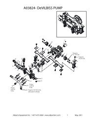
ILLUSTRATED<br />
PARTS<br />
BREAKDOWN<br />
150 MODEL<br />
2<br />
31<br />
1<br />
3<br />
9<br />
53<br />
56<br />
55<br />
32<br />
23<br />
24<br />
54<br />
52<br />
25<br />
47<br />
4<br />
5<br />
11<br />
18<br />
46<br />
10<br />
17<br />
37<br />
44<br />
26<br />
34<br />
33<br />
21<br />
38<br />
22<br />
12<br />
6<br />
7<br />
20<br />
29<br />
40<br />
41<br />
13<br />
15<br />
16<br />
15<br />
51<br />
35<br />
20<br />
42<br />
30<br />
14<br />
43<br />
13<br />
28<br />
45<br />
39<br />
36<br />
27<br />
19<br />
8<br />
10 100166
PARTS LIST<br />
150 MODEL<br />
OWNER’S MANUAL<br />
This list contains replaceable parts used in your heater. When ordering parts, be sure to provide the correct<br />
model and serial numbers (from the model plate), then the part number and description of the desired part.<br />
KEY PART<br />
NO. NUMBER DESCRIPTION QTY.<br />
KEY PART<br />
NO. NUMBER DESCRIPTION QTY.<br />
1 M51072-02AA Upper Shell (RM150E) 1<br />
M51072-02AB Upper Shell (BLP150E) 1<br />
079028-01AC Upper Shell (RLP150E) 1<br />
2 M15823-27 Screw, #10-16 x 1/2" 8<br />
3 099443-01 Combustion Chamber 1<br />
4 097805-01 Ignitor 1<br />
5 M10908-1 Screw, #6-32 x 1/4" 1<br />
6 M11084-39 Screw, #8 x 1/2" 1<br />
7 WLI-2BL Washer 1<br />
8 097806-02 Ignitor Cable 1<br />
9 M51108-01 Heat Shield 1<br />
10 M51153-01 Fan 1<br />
11 100298-01 Motor 1<br />
12 097776-01 Bushing 1<br />
13 097809-01 Male Fitting 2<br />
14 100301-01 Valve Bracket 1<br />
15 097803-01 Solenoid Valve 2<br />
16 097153-02 Pipe Nipple, 1/4 x 2" 1<br />
17 097905-02 Fuel Tube 1<br />
18 098425-01 Nozzle 1<br />
19 M12461-25 Screw, #10-32 x 1/4" 2<br />
20 M11084-26 Screw, #10 x 3/8" 10<br />
21 M50104-05 Bushing 1<br />
22 M50104-01 Bushing 1<br />
23 097952-07 Thermal Switch 1<br />
24 097968-01 Screw, #4-40 x 1/4" 2<br />
25 NPC-00C Nut, #4-40 2<br />
26 M51073-06AA Lower Shell (RM150E) 1<br />
M51073-06AB Lower Shell (BLP150E) 1<br />
M51073-06AC Lower Shell (RLP150E) 1<br />
27 097965-02AA Side Cover 1<br />
28 097462-01 On/Off Switch 1<br />
29 M12461-7 Screw, #6-32 x 1" 2<br />
30 099432-01 Nut, #6-32 2<br />
31 M51104-01 Handle 1<br />
32 M11084-29 Screw, #10 x 3/4" 2<br />
33 097964-03AA Fan Guard 1<br />
34 M51074-01 Motor Mounting Bracket 1<br />
35 M50400 Strain Relief Bushing 1<br />
36 097545-01 Power Cord 1<br />
37 M50631 Rubber Bumper 2<br />
38 NTC-4C Lock Nut, 1/4-20 2<br />
39 099157-01 Aluminum Rivet 1<br />
40 099125-06 Terminal Board 1<br />
41 097966-08AA Base 1<br />
42 M51605-04 Burner Control 1<br />
43 M10908-27 Screw, #10-32 x 1/2" 2<br />
44 M11271-8 U-Nut, #10 8<br />
45 100371-01 Lamp 1<br />
46 100299-01 Rear Plate 1<br />
47 097849-02 Burner Assembly 1<br />
48 M16841-62 Wire Assembly, Green 1<br />
49 M16841-55 Wire Assembly, Green 2<br />
50 097951-04 Wire Assembly, Brown 1<br />
51 M11084-37 Screw, #8 x 1/4" 2<br />
52 098428-01 Clip 1<br />
53 098406-01 Rivet 3<br />
54 NPC-4C Nut, 1/4-20 3<br />
55 WLI-4C Lock Washer 3<br />
56 098434-01 Spacer 3<br />
PARTS AVAILABLE – NOT SHOWN<br />
099596-05 Tradename Decal (RM150E) 2<br />
097940-03 Tradename Decal (BLP150E) 2<br />
097941-11 Tradename Decal (RLP150E) 2<br />
100181-01 General Information Decal 1<br />
100462-01 Operation Decal 1<br />
100372-01 Lamp Decal 1<br />
100168-01 Wiring <strong>Diagram</strong> Decal 1<br />
097953-02 Regulator/Hose Assembly 1<br />
49<br />
49<br />
Ignitor<br />
Orange<br />
Burner<br />
Control<br />
Green<br />
Blue<br />
Black<br />
Blue<br />
Brown<br />
White<br />
Green<br />
Solenoid<br />
Valve<br />
Blue<br />
Blue<br />
Connector<br />
Connector<br />
Green<br />
Blue<br />
Solenoid<br />
Valve<br />
T<br />
Thermal<br />
Switch<br />
Blue<br />
Motor<br />
Yellow<br />
Centrifugal<br />
Switch<br />
Yellow<br />
Connector<br />
Black<br />
Brown<br />
On/Off Switch<br />
White<br />
Terminal<br />
Board Lamp<br />
Blue Blue<br />
Brown<br />
Brown<br />
Green<br />
Green<br />
Power<br />
Cord<br />
Green<br />
Green<br />
150<br />
Model<br />
Only<br />
50<br />
48<br />
100166<br />
11
150 AND 300 MODELS<br />
PROPANE CONSTRUCTION HEATERS<br />
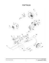
ILLUSTRATED<br />
PARTS<br />
BREAKDOWN<br />
300 MODEL<br />
2<br />
8<br />
4<br />
43<br />
1<br />
6<br />
7<br />
3<br />
5<br />
55<br />
10<br />
56<br />
44<br />
9<br />
43<br />
13<br />
53<br />
12<br />
43<br />
11<br />
52 51<br />
46<br />
15<br />
18<br />
46 47 18<br />
23<br />
16 45<br />
20<br />
21<br />
14<br />
43<br />
42<br />
27<br />
34<br />
37<br />
31<br />
32<br />
38<br />
30<br />
25<br />
54<br />
31<br />
33<br />
36<br />
28<br />
29<br />
22<br />
24<br />
39<br />
35<br />
26<br />
41<br />
40<br />
17<br />
44<br />
17<br />
19<br />
12 100166
PARTS LIST<br />
300 MODEL<br />
OWNER’S MANUAL<br />
This list contains replaceable parts used in your heater. When ordering parts, be sure to provide the correct<br />
model and serial numbers (from the model plate), then the part number and description of the desired part.<br />
KEY PART<br />
NO. NUMBER DESCRIPTION QTY.<br />
KEY PART<br />
NO. NUMBER DESCRIPTION QTY.<br />
1 097963-01AA Outer Shell (RM300E) 1<br />
097963-01AB Outer Shell (BLP300E) 1<br />
097963-01AC Outer Shell (RLP300E) 1<br />
2 097847-01 Combustion Chamber 1<br />
3 097952-06 Thermal Switch 1<br />
4 097968-01 Screw, #4-40 x 1/4" 2<br />
5 NPC-00C Nut, #4-40 2<br />
6 097917-01 Handle 1<br />
7 097918-01 Handle Cleat 2<br />
8 M12461-26 Screw, #10-32 x 3/8" 4<br />
9 NTF-3C Torque Nut, #10-32 4<br />
10 097930-01 Bushing 1<br />
11 097848-01 Rear Plate 1<br />
12 097805-01 Ignitor 1<br />
13 M10908-1 Screw, #6-32 x 1/4" 1<br />
14 097849-01 Burner Assembly 1<br />
15 097811-01 Fan 1<br />
16 100144-01 Motor 1<br />
17 NTC-4C Torque Nut, 1/4-20 8<br />
18 M12461-62 Screw, 1/4-20 x 3/8" 8<br />
19 097829-02 Motor Mount 1<br />
20 097964-01AA Fan Guard 1<br />
21 100311-01 Fuel Tube 1<br />
22 100146-01 Female Elbow 1<br />
23 099679-02 Nozzle 1<br />
24 097966-05AA Base 1<br />
25 099125-06 Terminal Board 1<br />
26 097462-01 On/Off Switch 1<br />
27 M51605-04 Burner Control 1<br />
28 097806-02 Ignitor Cable 1<br />
29 097809-01 Male Fitting 1<br />
30 100301-02 Valve Bracket 1<br />
31 097803-01 Solenoid Valve 2<br />
32 097153-02 Pipe Nipple 1<br />
33 M12461-25 Screw, #10-32 x 1/4" 2<br />
34 098825-01 Male Compression Elbow 1<br />
35 099157-01 Aluminum Rivet 1<br />
36 M10908-27 Screw, #10-32 x 1/2" 2<br />
37 M12461-7 Screw, #6-32 x 1" 2<br />
38 099432-01 Nut, #6-32 2<br />
39 100371-01 Lamp 1<br />
40 097545-01 Power Cord 1<br />
41 M50400 Strain Relief Bushing 1<br />
42 097965-01AA Side Cover 1<br />
43 M11084-26 Screw, #10-16 x 3/8" 19<br />
44 M50104-02 Bushing 3<br />
45 100373-01 Clamp 1<br />
46 M11084-39 Screw, #8-18 x 1/2" 2<br />
47 WLI-2BL Washer 1<br />
48 M16841-62 Wire Assembly, Green 1<br />
49 M16841-55 Wire Assembly, Green 2<br />
50 097951-04 Wire Assembly, Brown 1<br />
51 NPC-4C Nut, 1/4-20 3<br />
52 WLI-4C Lock Washer 3<br />
53 097839-01 Spacer 3<br />
54 M11084-37 Screw, #8 x 1/4" 2<br />
55 097916-01 Baffle 1<br />
56 099202-02 Rivet 3<br />
PARTS AVAILABLE – NOT SHOWN<br />
099596-06 Tradename Decal (RM300E) 2<br />
097895-03 Tradename Decal (BLP300E) 2<br />
097941-12 Tradename Decal (RLP300E) 2<br />
100180-01 General Information Decal 1<br />
100462-01 Operation Decal 1<br />
100372-01 Lamp Decal 1<br />
100168-01 Wiring <strong>Diagram</strong> Decal 1<br />
097953-02 Regulator/Hose Assembly 1<br />
49<br />
49<br />
Ignitor<br />
Orange<br />
Burner<br />
Control<br />
Green<br />
Blue<br />
Black<br />
Blue<br />
Brown<br />
Solenoid<br />
Valve<br />
Blue<br />
Blue<br />
Connector<br />
Connector<br />
Green<br />
Blue<br />
Solenoid<br />
Valve<br />
T<br />
Thermal<br />
Switch<br />
Blue<br />
Motor<br />
Yellow<br />
Brown<br />
On/Off Switch<br />
Blue<br />
Brown<br />
Green<br />
Centrifugal<br />
Switch<br />
Terminal<br />
Board<br />
Blue<br />
Brown<br />
Green<br />
Yellow<br />
Connector<br />
Black<br />
White<br />
Lamp<br />
Power<br />
Cord<br />
150<br />
Model<br />
Only<br />
50<br />
White<br />
Green<br />
Green<br />
Green<br />
48<br />
100166<br />
13
WARRANTY AND REPAIR SERVICE<br />
KEEP THIS WARRANTY<br />
LIMITED WARRANTY<br />
DESA International warrants this product and any parts thereof, to be free from defects in materials and workmanship for<br />
six (6) months from the date of first purchase when operated and maintained in accordance with instructions. This warranty<br />
is extended only to the original retail purchaser, when proof of purchase is provided.<br />
This warranty covers only the cost of parts required to restore the product to proper operating condition. Transportation and<br />
incidental costs associated with warranty parts are not reimbursable under this warranty.<br />
This warranty does not cover defects resulting from misuse, abuse, negligence, accidents, lack of proper maintenance,<br />
normal wear, alteration, modification, tampering, contaminated fuels, repair using improper parts, or repair by anyone other<br />
than an authorized dealer or service center. Routine maintenance is the responsibility of the owner.<br />
This express warranty is given in lieu of any other warranty either expressed or implied, including warranties of<br />
merchantability and fitness for a particular purpose.<br />
DESA International assumes no responsibility for indirect, incidental or consequential damages.<br />
We reserve the right to amend these specifications at any time without notice. The only warranty applicable is our<br />
standard written warranty. We make no other warranty, expressed or implied.<br />
Model<br />
Serial No.<br />
Date of Purchase<br />
DESA<br />
INTERNATIONAL<br />
2701 Industrial Drive<br />
P.O. Box 90004<br />
Bowling Green, KY 42102-9004<br />
U.S.A.<br />
For information, write: DESA International, P.O. Box 90004<br />
Bowling Green, Kentucky 42102-9004 U.S.A.<br />
ATTN: Customer Service Department<br />
When writing, always include model number and serial number.