Illustrated Parts Diagram - Allparts Equipment & Accessories
Illustrated Parts Diagram - Allparts Equipment & Accessories
Illustrated Parts Diagram - Allparts Equipment & Accessories

Create successful ePaper yourself
Turn your PDF publications into a flip-book with our unique Google optimized e-Paper software.
PRODUCTIDENTIFICATIONHot Air OutletUpper ShellHandleLower ShellFuel TankSide CoverFan GuardAir FilterEnd CoverFuel CapFlame-OutControl ResetButtonPowerCordFigure 1 - 35/70,000 Btu/Hr ModelsHot AirOutletUpper ShellLowerShellFuel CapFan GuardFuel TankSide CoverFlame-OutControl ResetButtonPower CordFigure 2 - 100/150,000 Btu/Hr Models4102685
UNPACKINGASSEMBLY(For 100,000 and 150,000Btu/Hr Models Only)1. Remove all packing items applied to heater for shipment.2. Remove all items from carton.3. Check items for any shipping damage. If heater is damaged, promptly informdealer where you bought heater.These models are furnished with wheels and handles. Wheels, handles, and themounting hardware are found in the shipping carton.Tools Needed• Medium Phillips Screwdriver• 3/8" Open or Adjustable Wrench• Hammer1. Slide axle through wheel support frame. Install wheels on axle.IMPORTANT: When installing wheels, point extended hub of wheels towardwheel support frame (see Figure 3).2. Place cap nuts on axle ends. Gently tap with hammer to secure.3. Place heater on wheel support frame. Make sure air inlet end (rear) of heater isover wheels. Line up holes on fuel tank flange with holes on wheel support frame.4. Place front handle and rear handle on top of fuel tank flange. Insert screwsthrough handles, fuel tank flange, and wheel support frame. Attach nut fingertight after each screw is inserted.5. After all screws are inserted, tighten nuts firmly.Front HandleHot AirOutletScrewRearHandleFuel TankFlangeAirInletWheelSupportFrameWheelNutCap NutAxleExtendedHubFigure 3 - Wheel and Handle Assembly, 100/150,000 Btu/Hr Models Only5102685
THEORY OFOPERATIONThe Fuel System: The air pump forces air through the air line. The air is thenpushed through the burner head nozzle. This air causes fuel to lift from the tank.A fine mist of fuel is sprayed into the combustion chamber.The Air System: The motor turns the fan. The fan pushes air into and aroundthe combustion chamber. This air is heated and provides a stream of clean, hotair.The Ignition System: The electronic ignitor sends voltage to the spark plug.The spark plug ignites the fuel and air mixture.The Flame-Out Control System: This system causes the heater to shut downif the flame goes out.Motor Air PumpCombustion Spark BurnerIntakeChamberPlugFanHeadAirFilterCleanHeatedAir OutCoolAirInOutputAirFilterFuelTankNozzleFuelFilterAir lineTo BurnerElectronicIgnitorAir For FuelSystemAir For CombustionAnd HeatingFuelFigure 4 - Cross Section Operational ViewFUELSWARNINGUse only kerosene or No. 1 fuel oil to avoid risk of fire orexplosion. Never use gasoline, naphtha, paint thinners,alcohol or other highly flammable fuels.Do not use heavy fuels such as No. 2 fuel oil or No. 2 Diesel. Using heavy fuelswill result in:• clogged fuel filter and nozzle• carbon build up on spark plug• use of non-toxic anti-icer in fuel during very cold weather6IMPORTANT: Use a KEROSENE ONLY container. Be sure storage container isclean. Foreign matter such as rust, dirt, or water will cause the flame-out controlto shut down heater. Foreign matter may also require you to clean fuel systemoften.102685
VENTILATIONWARNINGFollow the minimum fresh, outside air ventilationrequirements. If proper fresh, outside air ventilation is notprovided, carbon monoxide poisoning can occur. Provideproper fresh, outside air ventilation before running heater.Provide a fresh air opening of at least 2800 square cm (three square feet) for each100,000 Btu/Hr rating. Provide extra fresh air if more heaters are being used.Example: A 150,000 Btu/Hr heater requires one of the following:• a two-car garage door raised 15 cm (six inches)• a single-car garage door raised 23 cm (nine inches)• two, 76 cm (thirty-inch) windows raised 31 cm (twelve inches)OPERATIONWARNINGReview and understand the warnings in the SafetyInformation Section. They are needed to safely operate thisheater. Follow all local codes when using this heater.To Start Heater1. Follow all ventilation and safety information.2. Fill fuel tank with kerosene or No. 1 fuel oil.3. Attach fuel cap.4. Plug power cord of heater into standard 230 volt/50 hertz, grounded (earthed)outlet. Use an extension cord if needed. Use only a three-prong, grounded(earthed) extension cord.Extension Cord Wire Size RequirementsUp to 30.5 meters (100 feet) long, use 1.0 mm 2 (16 AWG) conductor30.6 to 61 meters (101 to 200 feet) long, use 1.5 mm 2 (14 AWG) conductorHeater will start when power cord is plugged into outlet. If not, push inflame-out control reset button (see Figures 5 and 6).Flame-Out ControlReset ButtonFlame-Out ControlReset ButtonFigure 5 - Flame-Out Control ResetButton, 35/70,000 Btu/HrFigure 6 - Flame-Out Control ResetButton, 100/150,000 Btu/HrContinued7102685
OPERATIONContinuedSTORING,TRANSPORTING,OR SHIPPINGTo Stop Heater1. Unplug power cord from outlet.To Restart Heater1. Wait 2 minutes after stopping heater.2. Repeat steps under To Start Heater, page 7.Note: If shipping, transport companies require fuel tanks to be empty.1. Drain fuel tank.Note: Some models have drain plug on underside of fuel tank. If so, removedrain plug to drain all fuel. If heater does not have drain plug, drain fuelthrough fuel cap opening. Be sure all fuel is removed.2. Replace drain plug if provided.3. If any debris is noted in old fuel, add 1 or 2 quarts of clean kerosene to tank,stir, and drain again. This will prevent excess debris from clogging filtersduring future use.4. Replace fuel cap or drain plug. Properly dispose of old and dirty fuel. Checkwith local automotive service stations that recycle oil.5. If storing, store heater in dry place. Make sure storage place is free of dustand corrosive fumes.IMPORTANT: Do not store kerosene over summer months for use during nextheating season. Using old fuel could damage heater.PREVENTATIVEMAINTENANCESCHEDULEWARNINGNever service heater while it is plugged in, operating, orhot. Severe burns and electrical shock can occur.Item How Often How ToFuel tank Flush every 150-200 hours See Storing, Transporting, orof operation or as needed. Shipping, above.Air output and Replace every 500 hours of See Air Output, Air Intake,lint filters operation or once a year. and Lint Filters, page 14.Air intake Wash and dry with soap and See Air Output, Air Intake,filter water every 500 hours of and Lint Filters, page 14.operation or as needed.Fuel filter Clean twice a heating season See Fuel Filter, page 11.or as needed.Spark plug Clean and regap every 600 See Spark Plug, pages 12 andhours operation or replace 13.as needed.Fan blades Clean every season or as needed. See Fan, page 18.MotorNot required/permanentlylubricated8102685
TROUBLE-SHOOTINGWARNINGNever service heater while it is plugged in, operating, or hot.Severe burns and electrical shock can occur.OBSERVED FAULT POSSIBLE CAUSE REMEDYHeater ignites, butflame-out controlshuts off heater aftera short period oftime.Wrong pump pressureDirty air output, air intake,and lint filtersDirty fuel filterDirt in nozzleDirty photocell lensBad flame-out controlSee Pump PressureAdjustment, page 14.See Air Output, Air Intakeand Lint Filters, page 14.See Fuel Filter, page 11.See Nozzle, pages 15 and16.Clean photocell lens.Replace flame-out control.Heater will notignite, but motor runsfor a short period oftime.Wrong pump pressureCarbon deposits on sparkplug and/or improper gapDirty fuel filterDirt in nozzleWater in fuel tankSee Pump PressureAdjustment, page 14.See Spark Plug, pages 12and 13.See Fuel Filter, page 11.See Nozzle, pages 15 and16.Drain and flush fuel tankwith clean kerosene.See Storing, Transporting,or Shipping, page 8.WARNING: High voltage!Motor does not startwhen heater isplugged in, fanrotates slowly ordoes not turn.Electronic ignitor notgrounded (earthed)Bad electronic ignitorFlame-out control not resetBinding pump rotorMake sure electronicignitor mounting is tight.Replace electronicignitor.Reset flame-out controlbutton, see Figures 5 and6, page 7.If fan is hard to turn, seePump Rotor, page 17.9102685
SERVICEPROCEDURESWARNINGNever service heater while it is plugged in, operating, orhot. Severe burns and electrical shock can occur.Upper Shell Removal1. Remove screws and lockwashers along each side ofheater using 5/16" nutdriver.These screwsattach upper and lowershells together.2. Lift upper shell off.3. Remove fan guard.UpperShellFan GuardFigure 7 - Upper Shell Removal, 35/70,000 Btu/Hr ModelsUpperShellFanGuardFigure 8 - Upper Shell Removal, 100/150,000 Btu/Hr Models10102685
Fuel Filter(35/70,000 Btu/Hr Models)1. Remove side cover screwsusing 5/16" nut-driver.2. Remove side cover.3. Pull rubber fuel line offfuel filter neck.4. Carefully pry bushing andfuel filter out of fuel tank.5. Wash fuel filter with cleanfuel and replace in tank.6. Attach rubber fuel line tofuel filter neck.7. Replace side cover.Fuel FilterSide CoverFuel LineFigure 9 - Fuel Filter Removal, 35/70,000 Btu/Hr ModelsFuel Filter(100/150,000 Btu/Hr Models)1. Remove side cover screwsusing 5/16" nut-driver.2. Remove side cover.3. Pull upper fuel line offfuel filter neck.4. Carefully pry bushing,lower fuel line, and fuelfilter out of fuel tank.5. Wash fuel filter with cleanfuel and replace in tank.6. Attach upper fuel line tofuel filter neck.7. Replace side cover.Fuel Filter, Bushing,and Lower Fuel LineUpperFuelLineSide CoverFigure 10 - Fuel Filter Removal, 100/150,000 Btu/Hr Models10268511
Spark Plug(35,000 Btu/Hr Model)1. Remove upper shell (seepage 10).2. Remove fan (see page18).3. Remove fuel and air linehoses from nozzleassembly.4. Remove spark plug wirefrom spark plug.5. Remove two screws using5/16" nut-driver andremove burner strap.6. Place hex-body of sparkplug into vise and tighten.7. Remove spark plugmounting nut using11/16" open-end wrench.8. Remove burner strapfrom spark plug.9. Clean and regap sparkplug electrodes to 1.4 mm(.055") gap.10. Replace burner strap ontospark plug. Rotate burnerstrap to position sparkplug electrodes (seeFigure 13).11. Tighten spark plug withspark plug mounting nut.12. Release hex-body ofspark plug from vise.13. Replace burner strap ontocombustion chamber.14. Attach spark plug wire tospark plug.15. Attach fuel and air linehoses to nozzle assembly.16. Replace fan (see page18).17. Replace fan guard andupper shell.CombustionChamberFigure 11 - Spark Plug Removal, 35,000 Btu/Hr ModelBurnerStrapSpark PlugMounting NutAir LineHoseFigure 12 - Spark Plug Gap, 35,000 Btu/Hr ModelBurnerStrapBurnerStrapSparkPlugNozzleAssemblyFuel LineHose1.4 mm (.055") GapSpark PlugWireBend Hereto AdjustGap12Figure 13 - Spark Plug Rotation, 35,000 Btu/Hr Model Only102685
Spark Plug(70/100/150,000 Btu/Hr Models)1. Remove upper shell (seepage 10).2. Remove fan (see page 18).3. Remove spark plug wirefrom spark plug.4. Remove spark plug fromburner head using 13/16"open-end wrench.5. Clean and regap sparkplug electrodes as follows:70/100,000 Btu/HrModels: 1.9 mm (.075")gap150,000 Btu/Hr Model:2.8 mm (.110") gap6. Install spark plug inburner head.7. Attach spark plug wire tospark plug.8. Replace fan (see page 18).9. Replace fan guard andupper shell.BurnerHeadSparkPlugSpark PlugWireFigure 14 - Spark Plug Removal, 70/100/150,000 Btu/Hr ModelsBend Hereto AdjustGapGapFigure 15 - Spark Plug Gap, 70/100/150,000 Btu/Hr Models10268513
Air Output, Air Intake,and Lint Filters1. Remove upper shell (seepage 10).2. Remove filter end coverscrews using 5/16" nutdriver.3. Remove filter end cover.4. Replace air output and lintfilters.5. Wash or replace air intakefilter (see PreventativeMaintenance Schedule,page 8).6. Replace filter end cover.7. Replace fan guard andupper shell.IMPORTANT: Do not oilfiltersLint FilterAir OutputFilterAir Intake FilterFilter EndCoverFigure 16 - Air Output, Air Intake, and Lint Filters,35/70,000 Btu/Hr ModelsAir Intake FilterFilter EndCoverFan GuardFan GuardLint FilterAir OutputFilterFigure 17 - Air Output, Air Intake, and Lint Filters,100/150,000 Btu/Hr ModelsPump PressureAdjustment1. Remove pressure gaugeplug from filter end cover.2. Install accessory pressuregauge (part numberHA1180).3. Start heater (see Operation,page 7). Allow motorto reach full speed.4. Adjust pressure. Turnrelief valve to right toincrease pressure. Turnrelief valve to left todecrease pressure. Seespecifications at right forcorrect pressure for eachmodel.5. Remove pressure gauge.Replace pressure gaugeplug in filter end cover.14PressureGaugePlugFigure 18 - Pressure Gauge Plug RemovalPumpModel Pressure(PSI/Bar)35,000 Btu/Hr 2.9/0.2070,000 Btu/Hr 3.8/0.26100,000 Btu/Hr 3.9/0.27150,000 Btu/Hr 4.8/0.33(35/70,000 Btu/Hr Models Shown)ReliefValvePressureGaugeFigure 19 - Adjusting Pump Pressure102685
Nozzle(35,000 Btu/Hr Model)1. Remove upper shell (seepage 10).2. Remove fan (see page18).3. Remove fuel and air linehoses from nozzle assembly.4. Turn nozzle assembly 1/4turn to left and pulltoward motor to remove.5. Place plastic hex-bodyinto vise and lightlytighten.6. Carefully remove nozzlefrom the nozzle adapterusing 5/8" socket wrench.7. Blow compressed air thruface of nozzle. This willfree any dirt in nozzlearea.8. Inspect nozzle seal fordamage.9. Replace nozzle intonozzle adapter untilnozzle seats. Tighten 1/3turn more using 5/8"socket wrench (4.5-5.1n-m/40-45 inch-pounds).10. Attach nozzle assembly toburner strap.11. Attach fuel and airlinehoses to nozzle assembly.12. Replace fan (see page 18).13. Replace fan guard andupper shell.CombustionChamberAir Line HoseFuel Line HoseFigure 20 - Removing Air and Fuel Line Hoses, 35,000 Btu/Hr ModelBurnerStrapNozzleAssemblyNozzleAssemblyFigure 21 - Removing Nozzle Assembly, 35,000 Btu/Hr ModelNozzleFaceNozzleSealNozzleNozzleAdapterAir lineFittingFuel lineFitting102685Figure 22 - Nozzle and Nozzle Adapter, 35,000 Btu/Hr Model15
Nozzle(70/100/150,000 Btu/Hr Models)1. Remove upper shell (seepage 10).2. Remove fan (see page18).3. Remove fuel and air linehoses from burner head.4. Remove spark plug wirefrom spark plug.5. Remove spark plug fromburner head using 13/16"open-end wrench.6. Remove three screwsusing 5/16" nut-driverand remove burner headfrom combustion chamber.7. Place burner head intovise and lightly tighten.8. Carefully remove nozzlefrom burner head using5/8" socket wrench (seeFigure 24).9. Blow compressed air thruface of nozzle. This willfree any dirt in nozzlearea.10. Inspect nozzle seal fordamage.11. Replace nozzle intoburner head and tightenfirmly (9.1-12.4 n-m/80-110 inch-pounds).12. Attach burner head tocombustion chamber.13. Install spark plug inburner head.14. Attach spark plug wire tospark plug.15. Attach fuel and airlinehoses to burner head.16. Replace fan (see page18).17. Replace fan guard andupper shell.ScrewCombustionChamberAir Line HoseBurner HeadSparkPlugFigure 23 - Removing Burner Head, 70/100/150,000 Btu/Hr ModelsNozzleFaceNozzleBurnerHeadFuel Line HoseNozzleSealAir lineFittingSpark PlugWireFuel lineFittingFigure 24 - Removing Nozzle, 70/100/150,000 Btu/Hr Models16102685
Pump Rotor(Procedure if rotor is binding)1. Remove upper shell (seepage 10).2. Remove filter end coverscrews using 5/16" nutdriver.3. Remove filter end coverand air filters.4. Remove pump platescrews using 5/16" nutdriver.5. Remove pump plate.6. Remove rotor, insert, andblades.7. Check for debris in pump.If debris is found, blowout with compressed air.8. Install insert and rotor.9. Check gap on rotor.Adjust to .076/.101 mm(.003"/.004") if needed(see Figure 27).Note: Rotate rotor onefull turn to insure the gap is.076/.101 mm (.003"/.004")at tightest position. Adjust ifneeded.10. Install blades, pumpplate, air filters, and filterend cover.11. Replace fan guard andupper shell.12. Adjust pump pressure(see page 14).Note: If rotor is still binding,proceed as follows.13. Perform steps 1 through 6above.14. Place fine grade sandpaper(600 grit) on flatsurface. Sand rotor lightlyin “figure 8” motion fourtimes (see Figure 28).15. Reinstall insert and rotor.16. Perform steps 10 through12 above.BladeFigure 25 - Rotor Location, 35/70,000 Btu/Hr ModelsInsertInsertRotorGap AdjustingScrewRotorAirOutputFilterFigure 26 - Rotor Location, 100/150,000 Btu/Hr ModelsGapAdjustingScrewFigure 27 - Gap AdjustingScrew LocationsBladeAir OutputFilterBladePumpPlatePumpPlateAirIntakeFilterFilter EndCoverAir IntakeFilterSandpaperFan Guard.076/.101 mm (.003"/.004") GapMeasured With Feeler GaugeRotorFilter EndCoverFan GuardFigure 28 - Sanding Rotor10268517
FanIMPORTANT: Remove fanfrom motor shaft beforeremoving motor from heater.The weight of the motorresting on the fan coulddamage the fan pitch.SetscrewFan1. Remove upper shell (seepage 10).2. Use 1/8" allen wrench toloosen setscrew whichholds fan to motor shaft.3. Slip fan off motor shaft.4. Clean fan using a softcloth moistened withkerosene or solvent.5. Dry fan thoroughly.6. Replace fan on motorshaft. Place fan hub flushwith end of motor shaft(see Figure 30).7. Place setscrew on flat ofshaft. Tighten setscrewfirmly (40-50 inchpounds/4.5-5.6n-m).8. Replace fan guard andupper shell.MotorShaftFigure 29 - Fan, Motor Shaft, and Setscrew LocationFanFlushMotorShaftSetscrewFigure 30 - Fan Cross SectionSPECIFICATIONS18Output Rating (Btu/Hr) 35,000 70,000 100,000 150,000FuelUse Only Kerosene or No. 1 Fuel OilFuel Tank Capacity(U.S. Gal./Liters) 3.0/11.4 5.0/18.9 9.0/34 13.5/51.1Fuel Consumption(Gal. Per Hr./Liters Per Hr.) .26/1.0 .49/1.85 .70/2.7 1.1/4.1Electric Requirements 230 V/50 Hz (Same All Models)Amperage (Normal Run) .8 1.0 1.2 1.2Hot Air Output (CFM/CMM) 140/4 225/6.4 425/12 500/14.2RPM 1425 2850 2850 2850102685
WIRINGDIAGRAMS230V/50HzBlue BrownRFI FilterWhiteBlackBlackGreen/YellowWhiteBGreen/YellowMotorOrangeIgnitorSpark PlugRedTerminalBoardWhiteRedBluePhotocellBlueFlame-OutControlRResetButtonRedFigure 31 - Wiring <strong>Diagram</strong>, 35/100/150,000 Btu/Hr Models230V/50HzBlue BrownRFI FilterWhiteBlackBlackGreen/YellowWhiteBGreen/YellowMotorOrangeIgnitorRedSpark PlugRedTerminalBoardWhiteRedBluePhotocellBlueFlame-OutControlRResetButtonBlack S or 2 M or 5MotorStartRelayL or 1RedFigure 32 - Wiring <strong>Diagram</strong>, 70,000 Btu/Hr Model10268519
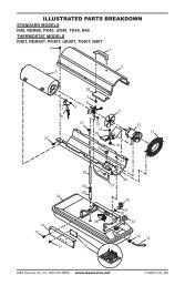
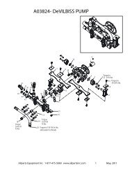
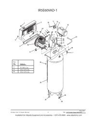
ILLUSTRATEDPARTSBREAKDOWN35,000 Btu/Hr Model431218-118-211-511-1568 117915 11-411-3132218132316172420222121333439274143 252926423730 281235323618-1822 14 1018-418-518-63811-2193118-318-74018-1718-1618-1518-1418-818-918-1018-1120Motor and Pump Assembly18-1318-12102685
PARTS LIST35,000 Btu/Hr ModelThis list contains replaceable parts used in your heater. When ordering parts, be sureto provide the correct model and serial numbers (from the model plate), then the partnumber and description of the desired part.KEY PART PARTNO. NUMBER DESCRIPTION QTY.1 M51104-01 Handle 12 098511-54 Upper Shell 13 102432-01 Screw/Lockwasher, 1/2" 64 098512-43 Combustion Chamber 15 M51108-01 Heat Shield 16 M11084-29 Screw, #10-16 x 3/4" 27 M16660 Photocell Bracket 18 M10908-2 Screw, #6-32 x 3/8" 29 HA3019 Photocell Assembly 110 079673-06 Power Cord 111 ** Burner Strap Assembly 111-1 097124-01 Bracket 111-2 HA3013 Spark Plug 111-3 079980-01 Nozzle Adapter 111-4 M29824 Nut, 14mm 111-5 HA3006 Nozzle 112 102801-01 Power Line RFI Filter 113 M30865-02 Bushing 214 M50400 Strain Relief Bushing 115 M30884 Fan 116 M50631 Rubber Bumper 217 101205-01 Motor Bracket 118 ** Motor and Pump Assembly 118-1 098642-02 Motor (230V/50Hz) 118-2 079975-03 Pump Body 118-3 M22009 Insert 118-4 M22456-2 Rotor 118-5 M29608 End Pump Cover 118-6 M29632 Lint Filter 118-7 M29633 Intake Filter 118-8 M29609 End Filter Cover 118-9 M12461-31 Screw, #10-32 x 1" 318-10 M8940 Steel Ball (1/4" Dia.) 118-11 M10993-1 Pressure Relief Spring 118-12 M27694 Adjusting Screw 118-13 M22997 Plug 118-14 M29612-01 Output Filter 118-15 M12461-32 Screw, #10-32 x 1 1/8" 6KEY PART PARTNO. NUMBER DESCRIPTION QTY.18-16 M50016 Elbow, 90˚ (Barb Fitting) 118-17 M8643-2 Blade 418-18 FHPF3-6C Screw, #10-32 x 3/4" 219 M51105-01 Fan Guard 120 NTC-4C Hex locknut 221 M50104-02 Bushing (wires) 222 102431-01 Screw/Lockwasher, 1/2" 1023 098511-12 Lower Shell 124 M11271-8 Clip Nut 625 RF3-6B Screw, #10-32 x 3/4" 126 M29652-04 Rubber Airline 127 M29652-05 Fuel Line 128 M16841-57 Wire Assembly (red 8 1/2") 129 M10990-3 Rubber Bushing 130 M50876-04 Fuel Filter Assembly 1(Includes bushing)31 102482-02 Electronic Ignitor 132 M11084-29 Screw, #10-16 x 3/4" 233 099125-02 Terminal Board 134 099157-01 Rivet 135 097630-02 Flame-Out Control 136 097702-01 Fuel Tank Cap 137 098513-73 Fuel Tank 138 M50899-03AA Side Cover 139 NPF-3B Nut, #10-32 340 099177-01 Hex Nut 141 078918-01 Terminal Board Tab Cap 142 097785-01 Vinyl Foam Gasket 143 WLE-3 Lock Washer, #10 2PARTS AVAILABLE - NOT SHOWNHA2210 Filler Neck Screen 1097649-01 Tradename Decal 2M9900-192 Combustion ChamberGround Wire 1102944-01 Decal Package 1**Not available as an assembly, order parts separately.10268521
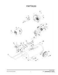
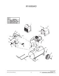
ILLUSTRATEDPARTSBREAKDOWN70,000 Btu/Hr Model4312567810141224231211251715162618192120Burner Head Assembly10-110-310-210-4 10-510-735433936293132413038214528441127223310-6373418-118-24018-1811 13918-418-518-618-318-74218-1718-1618-1518-818-918-1018-1418-1122Motor and Pump Assembly18-1318-12102685
PARTS LIST70,000 Btu/Hr ModelThis list contains replaceable parts used in your heater. When ordering parts, be sureto provide the correct model and serial numbers (from the model plate), then the partnumber and description of the desired part.KEY PART PARTNO. NUMBER DESCRIPTION QTY.1 M51104-01 Handle 12 098511-54 Upper Shell 13 102432-01 Screw/Lockwasher, 1/2" 64 098512-44 Combustion Chamber 15 M11084-29 Screw, #10-16 x 3/4" 26 M16660 Photocell Bracket 17 M10908-2 Screw, #6-32 x 3/8" 28 HA3019 Photocell Assembly 19 079673-06 Power Cord 110 ** Burner Head Assembly 110-1 HA3008 Nozzle 110-2 M10659-1 Nozzle Seal Washer 210-3 M10809-1 Nozzle Seal Spring 110-4 M8882 Nozzle Seal Sleeve 110-5 M51098-02 Burner Head Body 110-6 M50820-01 Barb Fitting 210-7 HA3012 Spark Plug 111 102431-01 Screw/Lockwasher, 1/2" 1112 M30865-02 Bushing 213 M50400 Strain Relief Bushing 114 M30884 Fan 115 M50631 Rubber Bumper 216 M12461-13 Screw, #8-32 x 1/4" 2(holds relay in position)17 101205-01 Motor/Relay Bracket 118 ** Motor and Pump Assembly 118-1 102001-16 Motor (230V/50Hz) 118-2 079975-02 Pump Body 118-3 M22009 Insert 118-4 M22456-1 Rotor 118-5 M29608 End Pump Cover 118-6 M29632 Lint Filter 118-7 M29633 Intake Filter 118-8 M29609 End Filter Cover 118-9 M12461-31 Screw, #10-32 x 1" 318-10 M8940 Steel Ball (1/4" Dia.) 118-11 M10993-1 Pressure Relief Spring 118-12 M27694 Adjusting Screw 118-13 M22997 Plug 118-14 M29612-01 Output Filter 1KEY PART PARTNO. NUMBER DESCRIPTION QTY.18-15 M12461-31 Screw, #10-32 x 1" 618-16 M50016 Elbow, 90˚ (Barb Fitting) 118-17 M8643 Blade 418-18 FHPF3-5C Screw, #10-32 x 5/8" 219 M51105-01 Fan Guard 120 NTC-4C Hex locknut 221 M50104-02 Bushing (wires) 222 102801-01 Power Line RFI Filter 123 098511-12 Lower Shell 124 M11271-8 Clip Nut 625 098136-05 Relay (motor start) 126 M16841-58 Wire Assembly (red 9 1/2") 127 RF3-6B Screw, #10-32 x 3/4" 128 M29652-04 Rubber Airline 129 079973-01 Fuel Line 130 M16841-57 Wire Assembly (red 8 1/2") 131 M10990-3 Rubber Bushing 132 M50876-05 Fuel Filter Assembly 1(Includes bushing)33 102482-02 Electronic Ignitor 134 M11084-29 Screw, #10-16 x 3/4" 235 099125-02 Terminal Board 136 099157-01 Rivet 137 097702-01 Fuel Tank Cap 138 097630-02 Flame-Out Control 139 098513-74 Fuel Tank 140 M50899-03AA Side Cover 141 NPF-3B Nut, #10-32 342 099177-01 Hex Nut 143 078918-01 Terminal Board Tab Cap 144 097785-01 Vinyl Foam Gasket 145 WLE-3 Lock Washer, #10 2PARTS AVAILABLE - NOT SHOWNHA2210 Filler Neck Screen 1097649-01 Tradename Decal 2M9900-192 Combustion ChamberGround Wire 1102944-02 Decal Package 1**Not available as an assembly, order parts separately.10268523
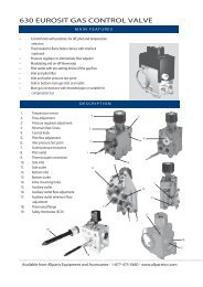
ILLUSTRATEDPARTSBREAKDOWN100,000 Btu/Hr Model2134 5812131478-110 11 179158-38-28-48-5313025262820218-6Burner Head Assembly8-72344362437333435181927922321638392913-113-2 13-313-4429434113-513-640613-713-1813-1713-813-1613-1513-1413-1313-913-1013-1124Motor and Pump Assembly13-12102685
PARTS LIST100,000 Btu/Hr ModelThis list contains replaceable parts used in your heater. When ordering parts, be sureto provide the correct model and serial numbers (from the model plate), then the partnumber and description of the desired part.KEY PART PARTNO. NUMBER DESCRIPTION QTY.1 098511-138 Upper Shell 12 102432-01 Screw/Lockwasher, 1/2" 83 098512-31 Combustion Chamber 14 M16660 Photocell Bracket 15 HA3019 Photocell Assembly 16 M27417 Drain Plug 17 M10908-2 Screw, #6-32 x 3/8" 28 ** Burner Head Assembly 18-1 100735-15 Nozzle 18-2 M10659-1 Nozzle Seal Washer 28-3 M10809-1 Nozzle Seal Spring 18-4 M8882 Nozzle Seal Sleeve 18-5 M50924-03 Burner Head Body 18-6 M50820-02 Barb Fitting 28-7 HA3012 Spark Plug 19 102431-01 Screw/Lockwasher, 1/2" 1310 M50814-06 Air Line 111 M51345-01 Fuel Line 112 102042-01 Fan 113 ** Motor and Pump Assembly 113-1 102001-03 Motor with capacitor(230V/50Hz) 113-2 079975-02 Pump Body 113-3 FHPF3-5C Screw, #10-32 x 5/8" 213-4 M22009 Insert 113-5 M22456-1 Rotor 113-6 M50545 End Pump Cover 113-7 M12179 Intake Filter 113-8 M16545 End Filter Cover 113-9 M8940 Steel Ball (1/4" Dia.) 113-10 M10993-1 Pressure Relief Spring 113-11 M27694 Adjusting Screw 113-12 M22997 Plug 113-13 M12461-31 Screw, #10-32 x 1" 413-14 M12244-1 Output Filter 113-15 M12461-31 Screw, #10-32 x 1" 613-16 M11637 Lint Filter 113-17 M50820-02 Barb Fitting 113-18 M8643 Blade 414 M51114-01 Fan Guard 1KEY PART PARTNO. NUMBER DESCRIPTION QTY.15 M50631 Rubber Bumper 216 097468-01 Edge Liner 117 101206-01 Motor and RelayBracket Assembly 118 WLE-3 Lock Washer, #10 219 NPF-3B Nut, #10-32 320 NTC-4C Hex locknut 221 102482-02 Electronic Ignitor 122 M11084-29 Screw, #10-16 x 3/4" 223 099125-02 Terminal Board 124 099157-01 Rivet 125 M50104-03 Bushing 126 M50104-03 Bushing 127 M50104-01 Bushing 228 099213-01 Button Plug 129 102801-01 Power Line RFI Filter 130 098511-191 Lower Shell 131 M11271-8 Clip Nut 832 RF3-6B Screw, #10-32 x 3/4" 133 M51150-01 Fuel filter 134 M10990-3 Rubber Bushing 135 M51151-01 Fuel Line 136 098513-75 Fuel Tank 137 097702-01 Fuel Tank Cap 138 M16841-57 Wire Assembly (red 8 1/2") 139 097630-02 Flame-Out Control 140 M50400 Strain Relief Bushing 141 079673-06 Power Cord 142 M51077-01AA Side Cover 143 099177-01 Hex Nut 144 078918-01 Terminal Board Tab Cap 1PARTS AVAILABLE - NOT SHOWNHA2210 Filler Neck Screen 1097650-01 Tradename Decal 2M9900-192 Combustion ChamberGround Wire 1102944-03 Decal Package 1**Not available as an assembly, order parts separately.10268525
ILLUSTRATEDPARTSBREAKDOWN150,000 Btu/Hr Model3214 5812131479158-18-38-28-48-531301025261117462820218-6Burner Head Assembly8-72344362437333435181927922321638392913-113-2 13-313-413-5424313-6640454113-713-1813-1713-813-1613-1513-1413-1313-913-1013-1126Motor and Pump Assembly13-12102685
PARTS LIST150,000 Btu/Hr ModelThis list contains replaceable parts used in your heater. When ordering parts, be sureto provide the correct model and serial numbers (from the model plate), then the partnumber and description of the desired part.KEY PART PARTNO. NUMBER DESCRIPTION QTY.1 098511-138 Upper Shell 12 102432-01 Screw/Lockwasher, 1/2" 83 098512-36 Combustion Chamber 14 099229-01 Photocell Bracket 15 HA3019 Photocell Assembly 16 M27417 Drain Plug 17 M10908-2 Screw, #6-32 x 3/8" 28 ** Burner Head Assembly 18-1 100735-11 Nozzle 18-2 M10659-1 Nozzle Seal Washer 28-3 M10809-1 Nozzle Seal Spring 18-4 M8882 Nozzle Seal Sleeve 18-5 M50924-08 Burner Head Body 18-6 M50820-02 Barb Fitting 28-7 HA3012 Spark Plug 19 102431-01 Screw/Lockwasher, 1/2" 910 M50814-06 Air Line 111 M51345-01 Fuel Line 112 102042-01 Fan 113 ** Motor and Pump Assembly 113-1 102001-03 Motor (with capacitor) 113-2 079975-03 Pump Body 113-3 FHPF3-6C Screw, #10-32 x 3/4" 213-4 M22009 Insert 113-5 M22456-2 Rotor 113-6 M50545 End Pump Cover 113-7 M12179 Intake Filter 113-8 M16545 End Filter Cover 113-9 M8940 Steel Ball (1/4" Dia.) 113-10 M10993-1 Pressure Relief Spring 113-11 M27694 Adjusting Screw 113-12 M22997 Plug 113-13 M12461-31 Screw, #10-32 x 1" 413-14 M12244-1 Output Filter 113-15 M12461-32 Screw, #10-32 x 1 1/8" 613-16 M11637 Lint Filter 113-17 M50820-02 Barb Fitting 113-18 M8643-2 Blade 414 M51114-01 Fan Guard 115 M50631 Rubber Bumper 2KEY PART PARTNO. NUMBER DESCRIPTION QTY.16 097468-01 Edge Liner 117 101206-01 Motor Bracket 118 WLE-3 Lock Washer, #10 219 NPF-3B Nut, #10-32 320 NTC-4C Hex locknut 221 102482-02 Electronic Ignitor 122 M11084-29 Screw, #10-16 x 3/4" 223 099125-02 Terminal Board 124 099157-01 Rivet 125 M50104-03 Bushing 126 M50104-03 Bushing 127 M50104-01 Bushing 228 099213-01 Button Plug 129 102801-01 Power Line RFI Filter 130 098511-191 Lower Shell 131 M11271-8 Clip Nut 832 RF3-6B Screw, #10-32 x 3/4" 133 M51150-01 Fuel filter 134 M10990-3 Rubber Bushing 135 M51151-02 Fuel Line 136 098513-76 Fuel Tank 137 097702-01 Fuel Tank Cap 138 M16841-57 Wire Assembly (red 8 1/2") 139 097630-02 Flame-Out Control 140 M50400 Strain Relief Bushing 141 079673-06 Power Cord 142 M51077-01AA Side Cover 143 M11084-27 Screw, #10-16 x 1/2" 444 078918-01 Terminal Board Tab Cap 145 099177-01 Hex Nut 146 097785-04 Vinyl Foam Gasket 2PARTS AVAILABLE - NOT SHOWNHA2210 Filler Neck Screen 1097650-01 Tradename Decal 2M9900-192 Combustion ChamberGround Wire 1102944-04 Decal Package 1**Not available as an assembly, order parts separately.10268527
WHEELS ANDHANDLES100,000 AND 150,000Btu/Hr MODELSKEY PART PART 100,000 150,000NO. NUMBER DESCRIPTION QTY. QTY.1 HA2203 Handles 2 —HA2204 Handles — 22 M12345-33 Screw, #10-24 x 1 3/4" 8 83 M12342-3 Wheel Support Frame 1 —M12831-3 Wheel Support Frame — 14 NTC-3C Hex Nut, #10-24 8 85 097896-03 Wheel 2 26 M28526 Cap Nut 2 27 M51015-01 Axle 1 —M16801-2 Axle — 1123547628102685
ACCESSORIESPurchase accessories fromyour local dealer.AIR GAUGE KIT - HA1180For all models. Special tool tocheck pump pressure.HEAVY DUTY WHEELS ANDHANDLE KIT - HA1202For heavy duty applications.Makes your heater even moreportable and convenient.For 35/70,000 Btu/Hr models.STANDARD WHEELS ANDHANDLE KIT - HA1206Makes heater even more portable andconvenient. Easy to assemble.For 35/70,000 Btu/Hr models.10268529
ECCONFORMITYDECLARATIONEC CONFORMITY DECLARATIONDESA Europe B.V.Innsbruckweg 144, 3047 AHPostbus 111583004 ED RotterdamHollandManufacturer:DESA International, Inc.2701 Industrial DriveBowling Green, KY 42101 U.S.A.Kerosene Portable Forced Air HeatersModel Numbers: B35CEA, B70CEA, B100CEA, B150CEAIt is declared that these models conform to the Machinery Directive 89/392/EEC,including 91/368/EEC. It is further declared that these models conform to the EMCDirective 89/336/EEC, amended by 92/31/EEC and including EN50081-1 andEN50082-1.We declare that the models noted are in conformity.CompanyDESA International, Inc.NameDouglas D. RohrerTitleVice President, Specialty Products Engineering03/15/96 — Bowling Green, KYDate and PlaceSignature30102685
NOTES10268531
WARRANTY AND REPAIR SERVICEDESA International warrants new Products sold by it to befree from defects in material or workmanship for a period ofninety days after date of delivery to the first user and subject tothe following conditions:DESA International's obligation and liability under thisWarranty is expressly limited to repairing or replacing at DESAInternational's option, any parts which appear to DESA Internationalupon inspection to have been defective in material orworkmanship when shipped from the factory. Such parts shallbe provided at no cost to the user, at the business establishmentof any factory authorized service center or the factory duringregular working hours. The Warranty shall not apply to componentparts or accessories of Products not manufactured byDESA International and which carry the warranty of the manufacturerthereof, or to normal maintenance (such as pressureadjustments) or to normal maintenance parts (such as filtersand spark plugs). Replacement or repair parts installed in theProduct covered by this Warranty are warranted only for theremainder of this Warranty as if such parts were original componentsof said Product. DESA INTERNATIONAL MAKES NOOTHER EXPRESS WARRANTY. TO THE EXTENT PERMIT-TED BY LAW DESA INTERNATIONAL MAKES NO IMPLIEDWARRANTY AND MAKES NO WARRANTY OF MER-CHANTABILITY OR FITNESS FOR ANY PARTICULAR PUR-CERTIFICATE OF GENERALEQUIPMENT - LIMITED 90 DAY WARRANTYPOSE. IN ANY EVENT IMPLIED WARRANTIES INCLUDINGTHOSE OF MERCHANTABILITY AND FITNESS FOR A PAR-TICULAR PURPOSE ARE LIMITED TO THE DURATION OFTHIS EXPRESS WARRANTY.Any transportation charges, costs of installation, duty,taxes or any other charges whatsoever must be borne by theuser. DESA International's obligation under this limited Warrantyshall not include any liability for direct, indirect, incidental,or consequential damage or delay. If requested by DESAInternational, Products or parts for which a warranty claim ismade are to be returned transportation prepaid by user to thefactory. Any improper use, including operation after discoveryof defective or worn parts, operation beyond capacity, substitutionof parts not approved by DESA International, or anyalteration or repair by others in such manner as in DESAInternational's judgement affects the Product materially andadversely, shall void this Warranty.NO EMPLOYEE OR REPRESENTATIVE IS AUTHORIZEDTO CHANGE THIS WARRANTY IN ANY WAY OR GRANTANY OTHER WARRANTY UNLESS SUCH CHANGE ISMADE IN WRITING AND SIGNED BY AN OFFICER OF DESAINTERNATIONAL AT ITS HOME OFFICE.WARRANTY SERVICEAlways specify model and serial numbers when communicatingwith the factory.We reserve the right to amend these specifications at any timewithout notice. The only Warranty applicable is our standardwritten Warranty. We make no other Warranty, expressed orimplied.A Service Manual is available by writing to the Technical ServiceDepartment at:Corporate Headquarters2701 Industrial DriveP.O. Box 90004Bowling Green, Kentucky 42102-9004U.S.A.Printed in U.S.A.