Illustrated Parts Diagram - Allparts Equipment & Accessories
Illustrated Parts Diagram - Allparts Equipment & Accessories
Illustrated Parts Diagram - Allparts Equipment & Accessories

Create successful ePaper yourself
Turn your PDF publications into a flip-book with our unique Google optimized e-Paper software.
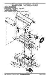
FanIMPORTANT: Remove fanfrom motor shaft beforeremoving motor from heater.The weight of the motorresting on the fan coulddamage the fan pitch.SetscrewFan1. Remove upper shell (seepage 10).2. Use 1/8" allen wrench toloosen setscrew whichholds fan to motor shaft.3. Slip fan off motor shaft.4. Clean fan using a softcloth moistened withkerosene or solvent.5. Dry fan thoroughly.6. Replace fan on motorshaft. Place fan hub flushwith end of motor shaft(see Figure 30).7. Place setscrew on flat ofshaft. Tighten setscrewfirmly (40-50 inchpounds/4.5-5.6n-m).8. Replace fan guard andupper shell.MotorShaftFigure 29 - Fan, Motor Shaft, and Setscrew LocationFanFlushMotorShaftSetscrewFigure 30 - Fan Cross SectionSPECIFICATIONS18Output Rating (Btu/Hr) 35,000 70,000 100,000 150,000FuelUse Only Kerosene or No. 1 Fuel OilFuel Tank Capacity(U.S. Gal./Liters) 3.0/11.4 5.0/18.9 9.0/34 13.5/51.1Fuel Consumption(Gal. Per Hr./Liters Per Hr.) .26/1.0 .49/1.85 .70/2.7 1.1/4.1Electric Requirements 230 V/50 Hz (Same All Models)Amperage (Normal Run) .8 1.0 1.2 1.2Hot Air Output (CFM/CMM) 140/4 225/6.4 425/12 500/14.2RPM 1425 2850 2850 2850102685