Illustrated Parts Diagram - Allparts Equipment & Accessories
Illustrated Parts Diagram - Allparts Equipment & Accessories
Illustrated Parts Diagram - Allparts Equipment & Accessories

Create successful ePaper yourself
Turn your PDF publications into a flip-book with our unique Google optimized e-Paper software.
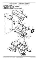
Spark Plug(35,000 Btu/Hr Model)1. Remove upper shell (seepage 10).2. Remove fan (see page18).3. Remove fuel and air linehoses from nozzleassembly.4. Remove spark plug wirefrom spark plug.5. Remove two screws using5/16" nut-driver andremove burner strap.6. Place hex-body of sparkplug into vise and tighten.7. Remove spark plugmounting nut using11/16" open-end wrench.8. Remove burner strapfrom spark plug.9. Clean and regap sparkplug electrodes to 1.4 mm(.055") gap.10. Replace burner strap ontospark plug. Rotate burnerstrap to position sparkplug electrodes (seeFigure 13).11. Tighten spark plug withspark plug mounting nut.12. Release hex-body ofspark plug from vise.13. Replace burner strap ontocombustion chamber.14. Attach spark plug wire tospark plug.15. Attach fuel and air linehoses to nozzle assembly.16. Replace fan (see page18).17. Replace fan guard andupper shell.CombustionChamberFigure 11 - Spark Plug Removal, 35,000 Btu/Hr ModelBurnerStrapSpark PlugMounting NutAir LineHoseFigure 12 - Spark Plug Gap, 35,000 Btu/Hr ModelBurnerStrapBurnerStrapSparkPlugNozzleAssemblyFuel LineHose1.4 mm (.055") GapSpark PlugWireBend Hereto AdjustGap12Figure 13 - Spark Plug Rotation, 35,000 Btu/Hr Model Only102685