Illustrated Parts Diagram - Allparts Equipment & Accessories
Illustrated Parts Diagram - Allparts Equipment & Accessories
Illustrated Parts Diagram - Allparts Equipment & Accessories

Create successful ePaper yourself
Turn your PDF publications into a flip-book with our unique Google optimized e-Paper software.
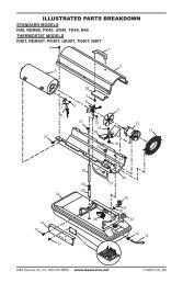
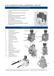
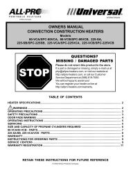
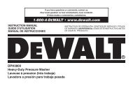
THEORY OFOPERATIONThe Fuel System: The air pump forces air through the air line. The air is thenpushed through the burner head nozzle. This air causes fuel to lift from the tank.A fine mist of fuel is sprayed into the combustion chamber.The Air System: The motor turns the fan. The fan pushes air into and aroundthe combustion chamber. This air is heated and provides a stream of clean, hotair.The Ignition System: The electronic ignitor sends voltage to the spark plug.The spark plug ignites the fuel and air mixture.The Flame-Out Control System: This system causes the heater to shut downif the flame goes out.Motor Air PumpCombustion Spark BurnerIntakeChamberPlugFanHeadAirFilterCleanHeatedAir OutCoolAirInOutputAirFilterFuelTankNozzleFuelFilterAir lineTo BurnerElectronicIgnitorAir For FuelSystemAir For CombustionAnd HeatingFuelFigure 4 - Cross Section Operational ViewFUELSWARNINGUse only kerosene or No. 1 fuel oil to avoid risk of fire orexplosion. Never use gasoline, naphtha, paint thinners,alcohol or other highly flammable fuels.Do not use heavy fuels such as No. 2 fuel oil or No. 2 Diesel. Using heavy fuelswill result in:• clogged fuel filter and nozzle• carbon build up on spark plug• use of non-toxic anti-icer in fuel during very cold weather6IMPORTANT: Use a KEROSENE ONLY container. Be sure storage container isclean. Foreign matter such as rust, dirt, or water will cause the flame-out controlto shut down heater. Foreign matter may also require you to clean fuel systemoften.102685