

Sliding and Rolling Bridge SolutionsâPart 1 - Aspire - The Concrete ...
Sliding and Rolling Bridge SolutionsâPart 1 - Aspire - The Concrete ...
Sliding and Rolling Bridge SolutionsâPart 1 - Aspire - The Concrete ...

Create successful ePaper yourself
Turn your PDF publications into a flip-book with our unique Google optimized e-Paper software.
<strong>Sliding</strong> <strong>and</strong> <strong>Rolling</strong> <strong>Bridge</strong><br />
Solutions–Part 1<br />
by Craig A. Shutt<br />
As owners look to save costs <strong>and</strong> erect bridges faster with<br />
less interference to the traveling public, the concepts of sliding<br />
<strong>and</strong> rolling bridges transversely into place after constructing<br />
them nearby are becoming more popular. <strong>The</strong>se techniques<br />
offer benefits, but they require unique considerations that can<br />
make the difference between success <strong>and</strong> failure. Both design<br />
<strong>and</strong> construction teams must underst<strong>and</strong> these movement<br />
considerations.<br />
<strong>Sliding</strong> or rolling bridges into place has become accepted by<br />
contractors due to the tighter time restrictions owners are placing<br />
on projects <strong>and</strong> their awareness of user costs for tying up either<br />
roadway access or waterways. <strong>The</strong>se approaches also can help<br />
minimize environmental impact during <strong>and</strong> after construction.<br />
In some cases, owners require this delivery method in their<br />
contract documents, necessitating designers <strong>and</strong> contractors to<br />
become familiar with the techniques as soon as they can. In these<br />
cases, clients often want to avoid employing cranes on small sites,<br />
which create economic drawbacks. On the plus side, owners<br />
don’t typically provide detailed requirements for how the bridge<br />
should be moved into place. When they do, they often allow<br />
contractors to propose alternatives, ensuring the most efficient<br />
approach can be employed.<br />
<strong>The</strong>re are three typical options when considering how to move<br />
bridges into place:<br />
• Pushing with hydraulic jacks on rollers or pads<br />
• Pulling with hydraulic jacks or cables on rollers or pads<br />
• Moving with self-propelled modular transporters (SPMTs)<br />
This article <strong>and</strong> the next in the ASPIRE accelerated bridge<br />
construction (ABC) series will deal with design issues of the first<br />
two types, sliding or rolling the components into place. <strong>The</strong>se<br />
will be followed by a look at necessary activities in the field<br />
during construction. <strong>The</strong> use of SPMTs will be addressed in a<br />
subsequent article.<br />
Define Duties<br />
Because few companies have deep experience with these<br />
projects yet, it is critical for engineers <strong>and</strong> contractors to<br />
define each member’s duties, requirements <strong>and</strong> who will be<br />
responsible for all the means <strong>and</strong> methods. Typically, the means<br />
<strong>and</strong> methods will derive from the contractor’s preference,<br />
based on the method with which the contractor is most<br />
comfortable.<br />
In creating a construction plan, the design team should develop<br />
an ABC strategy with requirements for as-builts or contingency<br />
ACCELERATED BRIDGE CONSTRUCTION<br />
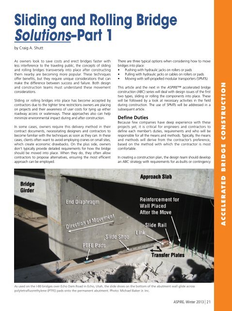
As used on the I-80 bridges over Echo Dam Road in Echo, Utah, the slide shoes on the bottom of the abutment wall glide across<br />
polytetrafluorethylene (PTFE) pads onto the permanent abutment. Photo: Michael Baker Jr. Inc.<br />
ASPIRE, Winter 2013 | 21
designed to support the bridge on the sliding shoes or rollers or<br />
the girders must be designed to accommodate both the sliding or<br />
rolling bearings <strong>and</strong> the permanent bearings.<br />
Throughout the process of designing <strong>and</strong> detailing the structure,<br />
construction sequencing should remain a priority. For instance,<br />
the lower diaphragms can be unstable during girder erection<br />
in its temporary condition because the lower diaphragm is only<br />
supported vertically on the temporary supports. This produces a<br />
partial hinge. Bracing the diaphragms until all girders are set <strong>and</strong><br />
the upper diaphragm concrete is placed eliminates this concern.<br />
<strong>Sliding</strong> Forces<br />
<strong>The</strong> designer should consider all the elements of the pushing or<br />
pulling system—ram, slide rail, <strong>and</strong> push blocks—when planning<br />
the process of moving the bridge into place. <strong>The</strong> pushing or<br />
pulling ram will most likely require a steel-to-steel connection, as<br />
it is the sole link allowing the structure to move. Details should<br />
allow the steel pushing or pulling block to be easily bolted on to<br />
the superstructure <strong>and</strong> then removed after the slide. <strong>Bridge</strong> skew<br />
can play a large part in the design of the pushing or pulling block.<br />
Jacking pockets in concrete end diaphragms are shown with the<br />
jacks. Photos: Horrock Engineers.<br />
plans <strong>and</strong> sequencing plans for closure periods for the road.<br />
Some departments of transportation have developed ABC<br />
specifications to cover additional requirements of the contractor<br />
or design-builder when utilizing ABC moving techniques. In<br />
some cases, these special provisions can become very specific.<br />
Too restrictive of an ABC specification can limit innovation during<br />
bidding.<br />
<strong>Concrete</strong> Solutions Available<br />
<strong>Concrete</strong> components provide many workable solutions for ABC.<br />
Some owners or contractors discourage the use of concrete when<br />
sliding components due to the added weight. <strong>The</strong> additional<br />
weight of concrete components is normally not a problem on<br />
bridge slides. <strong>The</strong> jacks typically have more capacity than needed.<br />
<strong>The</strong> increase in weight does impact the temporary-support<br />
structure. But in general, concrete components offer no more<br />
difficulties than other materials in construction <strong>and</strong> provide<br />
benefits in speed of delivery, better durability over the bridge’s<br />
service life, <strong>and</strong> less maintenance.<br />
<strong>The</strong> required force to move the bridge is a function of the weight<br />
of the superstructures <strong>and</strong> the coefficient of friction between the<br />
skid shoes <strong>and</strong> the polytetrafluorethylene (PTFE) pads over which<br />
the skid shoes slide or the rolling resistance of roller bearings.<br />
Coefficients of friction for PTFE bearings are given in the AASHTO<br />
LRFD <strong>Bridge</strong> Design Specifications, Chapter 14. Data are also<br />
available from product manufacturers.<br />
Based on recent project experience, static coefficients in the<br />
range of 0.09 to 0.12 <strong>and</strong> dynamic coefficients in the range of<br />
0.05 to 0.06 are reasonable values to consider for lubricated PTFE<br />
bearings sliding against polished stainless steel skid shoes.<br />
<strong>The</strong> pushing or pulling mechanisms should have a capacity in<br />
excess of the calculated pushing or pulling force. Some designers<br />
recommend that the entire moving system be designed for the<br />
full capacity of the hydraulic system so the connections cannot<br />
be over-loaded by the jacking system, in case the system binds up<br />
<strong>and</strong> is not immediately detected by the operator.<br />
Coordination early <strong>and</strong> often with the bridge-move subcontractor<br />
is highly recommended.<br />
Lightweight concrete can be used to mitigate the dead-load<br />
considerations, although it is not essential. Other options can<br />
optimize h<strong>and</strong>ling needs, including prestressing, post-tensioning,<br />
<strong>and</strong> the use of cast-in-place concrete joints.<br />
Superstructure Design<br />
Superstructure design of ABC bridges is generally the same as<br />
that used for conventional construction. <strong>The</strong> major difference<br />
occurs at the abutment. In the conventional bridge design, the<br />
girder loads pass directly into the abutment. When the bridge is<br />
rolled or slid, either the end diaphragms of the bridge have to be<br />
Push block between the hydraulic jack <strong>and</strong> the abutment must<br />
h<strong>and</strong>le an axial load plus a horizontal shear without damaging<br />
the end of the diaphragm. Photo: Horrock Engineers.<br />
22 | ASPIRE, Winter 2013
Approach Slabs<br />
In sliding- or rolling-bridge applications, moving the approach<br />
slabs along with the main span can be effective. This resolves key<br />
challenges affecting rideability of the roadway after construction<br />
<strong>and</strong> reduces closure times. Falsework <strong>and</strong> shoring can be<br />
designed to support the approach slabs during construction.<br />
<strong>The</strong>re can be dead-load deflection when casting the approach<br />
slabs on shored construction. This deflection can be h<strong>and</strong>led by<br />
recognizing its impact, <strong>and</strong> the benefits in speed <strong>and</strong> ultimate<br />
road smoothness are worth the effort. Shored construction will<br />
also result in compression in the top of the slab when the shoring<br />
is removed, possibly improving its cracking resistance.<br />
Expansion joints can be set in the approach slabs <strong>and</strong> locked<br />
into place until after the move. This allows the expansion to take<br />
place, after which the surface can be paved, if required. One<br />
team reported that this method saved critical time during the<br />
construction-launch period.<br />
Normally, the approach slab-to-bridge connection is designed to<br />
accommodate rotation. <strong>The</strong> approach slab will need to be lifted<br />
concurrently with the bridge if the rotation on the joint during<br />
the jacking <strong>and</strong> moving process exceeds the beam limit. If the<br />
expansion joint is at the end of the approach slab, then precast<br />
concrete sleeper slabs may be needed.<br />
Substructure Considerations<br />
A key temporary-foundation element involves designing piles<br />
or spread footings to support the bridge in its temporary<br />
position. Pile locations can be out of line by more than 6 in.,<br />
so it is critical that some tolerance is delineated for them to<br />
be welded to the slide rail-support system (which often is<br />
separate from the slide rails themselves) that will support the<br />
bridge during construction <strong>and</strong> during the move.<br />
One easy way to accomplish this is to weld an oversized<br />
plate onto the top of the pile. <strong>The</strong> plate can then support<br />
the slide-rail supports. In most cases, the slide rails require<br />
tight vertical tolerances. Allowing for adjustments in the<br />
slide-rail elevations to ensure a smooth <strong>and</strong> level sliding<br />
surface provides the best solution.<br />
Likewise, consideration should be given to the possibility<br />
that abutments will deflect when the bridge weight is<br />
moved into place. This typically isn’t noticed in a more<br />
traditional method of construction, using cranes or<br />
launchers, because that weight is added incrementally <strong>and</strong><br />
any deflections can be accommodated in the haunch or<br />
deck thickness. But when sliding the bridge into place, all of<br />
that significant weight is placed on the abutments at about<br />
the same time, so deflections of the permanent support<br />
from the partial <strong>and</strong> complete loading process need to be<br />
considered.<br />
<strong>The</strong>se adaptations need to be made at the design stage,<br />
as contractors must build the components to the plan<br />
dimensions to ensure the final bridge elevations match the<br />
required final profile. In some cases, when one abutment<br />
is out of line longitudinally, adjustments by the use of<br />
guide rails can be made to counteract anticipated <strong>and</strong><br />
unanticipated movements in unguided systems.<br />
Temporary strap tying the approach slab to the bridge deck<br />
slab. Photo: Horrock Engineers.<br />
Some tolerance is needed to allow for minor differences in<br />
the extensions of each jack. This difference in movement<br />
will rotate the structure in plan view. <strong>Bridge</strong>s have been<br />
successfully slid into place with less than a 2-in. tolerance<br />
allowance.<br />
Construction of new substructure elements around<br />
existing elements requires consideration of stability during<br />
construction. Temporary bracing of existing substructures or<br />
top-down retaining walls (soil nails or mechanically stabilized<br />
earth) may be required to ensure stability of the system<br />
during construction. Specifications defining construction<br />
submittals or design plans for shoring of the existing bridge<br />
should be included on the plan set.<br />
Soil nails or other bracing often are required, <strong>and</strong> their<br />
construction can make or break the schedule. Stabilizing<br />
this soil at the abutments is critical, as delays can result in all<br />
other scheduled activities being delayed as well. Significant<br />
<strong>and</strong> detailed analysis needs to be performed to ensure the<br />
temporary structures <strong>and</strong> existing spread footings, if used,<br />
will not settle once the dead loads are transferred.<br />
__________________<br />
This is the first in a series of articles examining different<br />
approaches to accelerated bridge construction. This report was<br />
produced from interviews with Hugh Boyle, chief engineer at<br />
H. Boyle Engineering; Mike Dobry, principal structures engineer,<br />
Larry Reasch, vice president <strong>and</strong> manager of the structures<br />
department, <strong>and</strong> Derek Stonebraker, structures engineer, at<br />
Horrock Engineers; R. Craig Finley Jr., founder <strong>and</strong> managing<br />
partner at Finley Engineering Group; <strong>and</strong> Steve Hague, chief<br />
bridge engineer at Burns & McDonnell.<br />
For additional photographs or information on this or other<br />
features, visit www.aspirebridge.org <strong>and</strong> open Current Issue.<br />
ACCELERATED BRIDGE CONSTRUCTION<br />
ASPIRE, Winter 2013 | 23


