

Forty Foot Pedestrian Bridge - Aspire - The Concrete Bridge Magazine
Forty Foot Pedestrian Bridge - Aspire - The Concrete Bridge Magazine
Forty Foot Pedestrian Bridge - Aspire - The Concrete Bridge Magazine

You also want an ePaper? Increase the reach of your titles
YUMPU automatically turns print PDFs into web optimized ePapers that Google loves.
<strong>Forty</strong> <strong>Foot</strong> <strong>Pedestrian</strong> <strong>Bridge</strong><br />
by William Collins, Simone Collins Inc.<br />
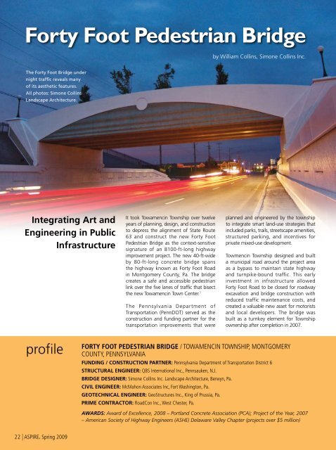
<strong>The</strong> <strong>Forty</strong> <strong>Foot</strong> <strong>Bridge</strong> under<br />
night traffic reveals many<br />
of its aesthetic features.<br />
All photos: Simone Collins<br />
Landscape Architecture.<br />
Integrating Art and<br />
Engineering in Public<br />
Infrastructure<br />
It took Towamencin Township over twelve<br />
years of planning, design, and construction<br />
to depress the alignment of State Route<br />
63 and construct the new <strong>Forty</strong> <strong>Foot</strong><br />
<strong>Pedestrian</strong> <strong>Bridge</strong> as the context-sensitive<br />
signature of an 8100-ft-long highway<br />
improvement project. <strong>The</strong> new 40-ft-wide<br />
by 80-ft-long concrete bridge spans<br />
the highway known as <strong>Forty</strong> <strong>Foot</strong> Road<br />
in Montgomery County, Pa. <strong>The</strong> bridge<br />
creates a safe and accessible pedestrian<br />
link over the five lanes of traffic that bisect<br />
the new Towamencin Town Center. 1<br />
<strong>The</strong> Pennsylvania Department of<br />
Transportation (PennDOT) served as the<br />
construction and funding partner for the<br />
transportation improvements that were<br />
planned and engineered by the township<br />
to integrate smart land-use strategies that<br />
included parks, trails, streetscape amenities,<br />
structured parking, and incentives for<br />
private mixed-use development.<br />
Towmencin Township designed and built<br />
a municipal road around the project area<br />
as a bypass to maintain state highway<br />
and turnpike-bound traffic. This early<br />
investment in infrastructure allowed<br />
<strong>Forty</strong> <strong>Foot</strong> Road to be closed for roadway<br />
excavation and bridge construction with<br />
reduced traffic maintenance costs, and<br />
created a valuable new asset for motorists<br />
and local developers. <strong>The</strong> bridge was<br />
built as a turnkey element for Township<br />
ownership after completion in 2007.<br />
profile<br />
<strong>Forty</strong> <strong>Foot</strong> <strong>Pedestrian</strong> <strong>Bridge</strong> / Towamencin Township, Montgomery<br />
County, Pennsylvania<br />
Funding / Construction Partner: Pennsylvania Department of Transportation District 6<br />
Structural Engineer: QBS International Inc., Pennsauken, N.J.<br />
<strong>Bridge</strong> Designer: Simone Collins Inc. Landscape Architecture, Berwyn, Pa.<br />
Civil Engineer: McMahon Associates Inc, Fort Washington, Pa.<br />
Geotechnical Engineer: GeoStructures Inc., King of Prussia, Pa.<br />
Prime Contractor: RoadCon Inc., West Chester, Pa.<br />
Awards: Award of Excellence, 2008 – Portland <strong>Concrete</strong> Association (PCA); Project of the Year, 2007<br />
– American Society of Highway Engineers (ASHE) Delaware Valley Chapter (projects over $5 million)<br />
22 | ASPIRE, Spring 2009
Infrastructure as<br />
Community Fabric<br />
From the start, Towamencin Township<br />
envisioned the highway project to<br />
be an essential part of the revitalized<br />
community landscape—in terms of<br />
walkability and physical character. When<br />
a central pedestrian bridge was selected<br />
as the preferred alternative for crossing<br />
the highway, the prominent location<br />
demanded functions and aesthetics above<br />
the ordinary.<br />
<strong>Concrete</strong> was selected for its economy,<br />
durability, and plastic qualities that could<br />
deliver a seamless aesthetic in a single<br />
structural and artistic material. <strong>The</strong><br />
sculptural potential of concrete inspired<br />
a collaborative process between the<br />
bridge designer and structural engineer<br />
to incorporate art considerations within<br />
the engineering decisions. <strong>The</strong> result is<br />
a practical synthesis of conventional<br />
materials and techniques with strategically<br />
selected, custom concrete treatments for<br />
aesthetics in high–priority elements.<br />
Geometry as an Aesthetic<br />
Program Element<br />
<strong>The</strong> <strong>Forty</strong> <strong>Foot</strong> <strong>Bridge</strong> design consciously<br />
features and mitigates specific geometric<br />
proportions. <strong>The</strong> clear span from center<br />
to center of bearings is 78 ft 6 in. Fascia<br />
beams are engineered as structural<br />
members up to 12 ft deep and 90 ft long,<br />
with integrally-formed architecture. Beam<br />
depths were selected to create parapets to<br />
cloister the pedestrian environment from<br />
the traffic below. <strong>The</strong> bridge’s width is 40 ft<br />
with curving, cast-in-place planters on both<br />
sides of the concrete deck to modulate<br />
space within the inside faces of the<br />
parapets by defining a sweeping, variablewidth<br />
promenade. <strong>Pedestrian</strong> lighting<br />
was designed for safety and ambiance.<br />
<strong>The</strong> cartway is wide enough to serve as a<br />
“civic” space for periodic functions within<br />
the town center. <strong>The</strong> cambered deck serves<br />
pedestrian and bicycle traffic only, but is<br />
engineered to support an H-20 truck load<br />
for maintenance and emergency vehicles.<br />
Engineering Innovation –<br />
Fascia Beams and Haunched<br />
Box Beams<br />
<strong>The</strong> fascia beams are uninterrupted,<br />
full-span, full-height beams that extend<br />
above the deck elevation to create the<br />
appearance of a rigid frame. <strong>The</strong>y are,<br />
however, simple span reinforced concrete<br />
beams designed to sit on cast-in-place<br />
concrete abutments with standard<br />
Far Left: View of pedestrian<br />
environment toward south portal<br />
showing the concrete deck with<br />
cast-in-place planters.<br />
Middle: Exposed aggregate structural<br />
deck. Planter wall forms were designed<br />
to echo the parapet line and the<br />
wingwall rustications.<br />
Right: Structural pylons are clad with<br />
architectural wingwall panels, mirrored<br />
inside and out. Globe lights were<br />
mounted on custom formed pylon caps.<br />
<strong>The</strong> sculptural potential of concrete inspired a<br />
collaborative process between the bridge designer<br />
and structural engineer…<br />
PRECAST, PRESTRESSED CONCRETE BOX BEAMS AND CAST-IN-PLACE FASCIA BEAMS WITH INTEGRAL<br />
ARCHITECTURE / TOWAMENCIN TOWNSHIP, OWNER<br />
<strong>Concrete</strong> Supplier: Berks Products, Allentown, Pa.<br />
White Cement Supplier: Lehigh White Cement, Allentown, Pa.<br />
Precaster for Box Beams: Schuylkill Products Inc., Cressona, Pa., a PCI-certified producer<br />
Precaster for MSE Wall and Cap Finials: <strong>The</strong> Reinforced Earth Company, Vienna, Va.<br />
Precaster for Finials and Pylon Caps: Architectural Precast Inc., Burlington, Ky.<br />
<strong>Bridge</strong> Description: An 80-ft-clear span by 40-ft-wide pedestrian bridge, exposed aggregate structural deck on conventional spread box beams,<br />
and ornamental fascia beams<br />
<strong>Bridge</strong> Construction Cost: $1 million for the bridge as part of a $13 million highway reconstruction project<br />
ASPIRE, Spring 2009 | 23
<strong>The</strong> East fascia beam<br />
showing the rippled<br />
form, abutments,<br />
paver-faced sloped<br />
walls, MSE walls with<br />
precast cap finials,<br />
precast wingwalls,<br />
and pylon cap.<br />
More and more<br />
modern infrastructure<br />
will be needed to relate<br />
to increasing numbers<br />
of people outside of<br />
vehicles and moving at<br />
the speed of foot traffic.<br />
A view of portal with box<br />
beams, corrugated deck pans,<br />
and fascia beam in place.<br />
Note the haunch on the fascia<br />
beam to support the cast-inplace<br />
structural deck.<br />
laminated neoprene bearing pads. Fascia<br />
beams were engineered to act as standard<br />
load-bearing concrete stringers. <strong>The</strong>y<br />
serve as hybrid members with modified<br />
geometry that allows the beams to include<br />
the safety functions of concrete parapets,<br />
the sound-dampening functions of sound<br />
walls, and the expansive surfaces for art<br />
forms—all within the new concrete beam<br />
design. <strong>The</strong> L-shaped fascia beams vary in<br />
depth from 12 ft at midspan to 8 ft 8 in.<br />
over the supports and have a thickness<br />
that varies from 18 in. to 20 in.<br />
Within each fascia, 15 epoxy-coated<br />
No. 7 bars provide the primary flexural<br />
reinforcement, and epoxy-coated No. 4<br />
stirrups act as shear reinforcement. <strong>The</strong><br />
ends of the beams cantilever behind the<br />
abutments toward structural pylons where<br />
both are clad with precast architectural<br />
wingwall panels. <strong>The</strong> structural concrete<br />
deck bears on interior haunches of the<br />
fascia beams. This design allows deck<br />
edges to be hidden behind the fascia<br />
beams, so that the structural deck is only<br />
exposed as the wearing surface with<br />
aesthetic treatments. <strong>Concrete</strong> buttresses<br />
hidden within the cast-in-place planters tie<br />
the fascia beams structurally to the deck.<br />
<strong>The</strong> concrete deck is also supported by<br />
three interior 48-in.-wide by 39-in.-deep<br />
precast, prestressed concrete box beams.<br />
<strong>The</strong> beams were haunched 13 in. to simplify<br />
the forming and casting of the cambered<br />
deck. <strong>The</strong> beams varied in depth from 39<br />
in. at the supports to 52 in. at midspan.<br />
<strong>The</strong> interior void form varied in depth as<br />
well, maintaining a constant 3-in.-thick top<br />
flange and 5½-in.-thick bottom flange.<br />
Art and Architecture<br />
<strong>The</strong> architecture of <strong>Forty</strong> <strong>Foot</strong> <strong>Bridge</strong><br />
acknowledges typical structural features<br />
such as corbels, spring points, camber,<br />
hinges, and keystones. Art lines in the<br />
concrete are graphic interpretations of<br />
forces alive within the bridge, including<br />
tension, compression, bearing, and<br />
repose.<br />
<strong>The</strong> Art Deco motif responds to the bold<br />
engineering by exploiting the concrete<br />
material to form elegant, archetypal arch<br />
shapes as shadowed relief, designed<br />
to “lighten” the apparent mass of the<br />
deceptively large fascia beams. Below<br />
the arches, the art of the ripple art forms<br />
change frequency to express the fluid<br />
nature of movements below a bridge, and<br />
functionally create horizontal shadow lines<br />
designed to subtly elongate the bridge<br />
visually and “de-emphasize” the sense of<br />
its vertical dimension.<br />
CAD-generated documents for computercut,<br />
styrene formliners were used to create<br />
molds up to 4 in. deep for the surface<br />
topography within the fascia beams. <strong>The</strong><br />
curved top of the fascia beams was an<br />
aesthetic decision accommodated by the<br />
engineering to soften the shape, reduce<br />
visual “mass,” and create the top line of<br />
the perceived arch in the fascia beam.<br />
Color for concrete surfaces was specified<br />
conservatively to allow for multiple field<br />
mock-ups and photo-rendering studies of<br />
the actual structure during construction.<br />
Color selections were simplified to two<br />
colors and bright white. A light green<br />
was used below the arch shape to make<br />
the rippled surface visually “recede,”<br />
creating the effect from a distance that<br />
it blends with the sky and landscape<br />
beyond, making the slender white arch<br />
shape over the road appear to leap to<br />
the foreground. All finished concrete<br />
surfaces were treated with a transparent<br />
gloss urethane sealant.<br />
24 | ASPIRE, Spring 2009
Foundations, Retaining Walls,<br />
and Sloped Paver Walls<br />
<strong>The</strong> substructures are conventional concrete<br />
abutments using standard formliners to<br />
match the rustications of the adjacent<br />
precast mechanically stabilized earth<br />
(MSE) retaining walls. Custom-cast finials<br />
terminate the lines of standard MSE wall<br />
caps at the abutments. Four 85-ft-long MSE<br />
retaining walls create the grade separation<br />
along the depressed <strong>Forty</strong> <strong>Foot</strong> Road.<br />
<strong>The</strong> sloped paver walls above the MSE<br />
retaining walls were designed at a 1:1<br />
gradient to be visible from all directions, and<br />
are essential to the success of the design—<br />
providing a sense of openness, light, and<br />
visual access between the roadway and<br />
pedestrian environments. <strong>The</strong> 45 degree<br />
walls also serve to limit the height of the<br />
retaining walls to 8 ft, prevent a “tunnel”<br />
effect under the bridge, and expose the<br />
wingwalls as visible “pylon” elements—all<br />
effectively elongating the visual sense of<br />
the bridge.<br />
<strong>The</strong> arches formed in the fascia beams<br />
appear to “spring” from the sloped bearing<br />
line formed in the pylon panels. Structurally,<br />
the sloped walls act as compressive<br />
structures to bear against the MSE walls<br />
and are tied into grade using the same<br />
conventional geogrid reinforcement as the<br />
vertical walls. <strong>Concrete</strong> unit “brick” pavers<br />
were laid on a mortar bed in a fan pattern<br />
with dark mortar to reduce contrast.<br />
Required roadway clearance below the<br />
bridge was achieved by partially depressing<br />
the highway and partially elevating the<br />
bridge to create subtle 3% approach<br />
gradients that allow complete visibility<br />
under the bridge to the surrounding town<br />
center landscape.<br />
Conclusion<br />
<strong>The</strong> highway project, including the <strong>Forty</strong><br />
<strong>Foot</strong> <strong>Bridge</strong>, was let by PennDOT under<br />
the state contracting process, and the<br />
lowest prequalified bidder was selected.<br />
<strong>The</strong> product demonstrates that capable<br />
fine craftsmanship is available within the<br />
industry to deliver a project with exacting,<br />
custom aesthetic specifications.<br />
<strong>The</strong> success of the fascia beam concept<br />
relied completely on engineering innovation<br />
to create an extraordinary venue for<br />
the proposed artwork, to achieve a rare<br />
collaboration where art considerations<br />
affect geometry, engineering, and construction<br />
methods. <strong>The</strong> jury for the 2008 PCA<br />
<strong>Concrete</strong> <strong>Bridge</strong> Awards said <strong>Forty</strong> <strong>Foot</strong><br />
<strong>Bridge</strong>, “…is in itself a work of art.” <strong>The</strong><br />
visual harmony and scale of <strong>Forty</strong> <strong>Foot</strong><br />
<strong>Bridge</strong> succeeds in creating an inviting civic<br />
“place” and a landmark for both motorists<br />
and pedestrians. <strong>The</strong> structure features<br />
modern engineering design infused with<br />
a restrained aesthetic that salutes the<br />
inspiration of the historic Merritt Parkway<br />
bridges built in the 1930s.<br />
With a pending economic stimulus package<br />
and promised rush of infrastructure projects<br />
in 2009, we understand that what we build<br />
today lives with us for the next half century<br />
or more. Enduring infrastructure and<br />
quality jobs require smart choices to ensure<br />
that our special places are protected and<br />
improved by new projects that incorporate<br />
the combined talents of engineers, artists,<br />
and craftspersons. More and more modern<br />
infrastructure will be needed to relate to<br />
increasing numbers of people outside of<br />
vehicles and moving at the speed of foot<br />
traffic. <strong>Forty</strong> <strong>Foot</strong> <strong>Bridge</strong> is an example of a<br />
21st Century project that borrows the best<br />
from two previous “eras of infrastructure”<br />
by incorporating humanizing art features<br />
that gave public works projects of the 1930s<br />
depression-era their unique personalities,<br />
with typical standardized, mass-produced<br />
efficiencies ushered in with the products of<br />
the Interstate Highway System of the 1950s.<br />
Reference<br />
1.<br />
Collins, William, John Ruff, Kristen<br />
York, and Bashar S. Qubain, 2008,<br />
“<strong>Forty</strong> <strong>Foot</strong> Road <strong>Pedestrian</strong> <strong>Bridge</strong>:<br />
Integrating Aesthetics and Engineering,”<br />
Proceedings of the PCI-FHWA National<br />
<strong>Bridge</strong> Conference, October 5-7,<br />
Orlando, Fla., 22 pp.<br />
____________<br />
William Collins is vice president, Simone<br />
Collins Inc. Landscape Architecture,<br />
Berwyn, Pa.<br />
For more information on this or other<br />
projects, visit www.aspirebridge.org.<br />
ASPIRE, Spring 2009 | 25
<strong>Forty</strong> <strong>Foot</strong> <strong>Pedestrian</strong> <strong>Bridge</strong> / Towamencin Township, Montgomery County, Penn.<br />
Web | ASPIRE, Spring 2009<br />
Photo: Simone Collins Landscape Architecture.
<strong>Forty</strong> <strong>Foot</strong> <strong>Pedestrian</strong> <strong>Bridge</strong> / Towamencin Township, Montgomery County, Penn.<br />
Photo: Simone Collins Landscape Architecture.<br />
ASPIRE, Spring 2009 | Web
<strong>Forty</strong> <strong>Foot</strong> <strong>Pedestrian</strong> <strong>Bridge</strong> / Towamencin Township, Montgomery County, Penn.<br />
<strong>The</strong> <strong>Forty</strong> <strong>Foot</strong> <strong>Bridge</strong> under night traffic reveals many of its aesthetic features. Photo: Simone Collins Landscape Architecture.<br />
Web | ASPIRE, Spring 2009<br />
Photo: Simone Collins Landscape Architecture.
<strong>Forty</strong> <strong>Foot</strong> <strong>Pedestrian</strong> <strong>Bridge</strong> / Towamencin Township, Montgomery County, Penn.<br />
<strong>The</strong> 13-in.-deep haunches on the box beams and<br />
fascia panels can be easily seen with the deck forms<br />
in place. Providing haunches simplified forming, tying<br />
reinforcement, and placing concrete for the cambered<br />
deck. Paint on the deck form outlines the shape of a<br />
cast-in-place concrete planter. Photo: Simone Collins<br />
Landscape Architecture.<br />
Structural Components:<br />
Abutments—conventional cast in place with<br />
structural pylons<br />
Retaining Walls—conventional precast MSE panels<br />
and caps, with geogrid reinforcing<br />
Superstructure—hybrid design – with three<br />
conventional precast box girders<br />
and two custom, cast in place fascia<br />
beams<br />
Deck—Cast in place, exposed aggregate structural<br />
deck<br />
Landscape Planters—custom, cast in place planter<br />
walls on structural deck<br />
Architectural Wingwalls—custom, precast panels,<br />
caps and finials, cladding<br />
structural pylons<br />
Sloped Walls—conventional concrete paver blocks<br />
ASPIRE, Spring 2009 | Web
<strong>Forty</strong> <strong>Foot</strong> <strong>Pedestrian</strong> <strong>Bridge</strong> / Towamencin Township, Montgomery County, Penn.<br />
Web | ASPIRE, Spring 2009<br />
Photo: Simone Collins Landscape Architecture.
<strong>Forty</strong> <strong>Foot</strong> <strong>Pedestrian</strong> <strong>Bridge</strong> / Towamencin Township, Montgomery County, Penn.<br />
Photo: Simone Collins Landscape Architecture.<br />
ASPIRE, Spring 2009 | Web
<strong>Forty</strong> <strong>Foot</strong> <strong>Pedestrian</strong> <strong>Bridge</strong> / Towamencin Township, Montgomery County, Penn.<br />
Web | ASPIRE, Spring 2009<br />
Photo: Simone Collins Landscape Architecture.
<strong>Forty</strong> <strong>Foot</strong> <strong>Pedestrian</strong> <strong>Bridge</strong> / Towamencin Township, Montgomery County, Penn.<br />
Photo: Simone Collins Landscape Architecture.<br />
ASPIRE, Spring 2009 | Web
<strong>Forty</strong> <strong>Foot</strong> Road <strong>Pedestrian</strong> <strong>Bridge</strong>:<br />
Integrating Aesthetics and Engineering<br />
William Collins, RLA, ASLA, Simone Collins Landscape Architecture, Berwyn, PA<br />
John Ruff, P.E., Senior Structural Engineer, QBS International Inc. Pennsauken, NJ<br />
Kristen York, P.E., McMahon Associates Inc., Fort Washington, PA<br />
Bashar S. Qubain, Ph.D., P.E., President, GeoStructures Inc., King of Prussia, PA<br />
ABSTRACT<br />
<strong>Forty</strong> <strong>Foot</strong> Road <strong>Pedestrian</strong> <strong>Bridge</strong> is an 80-foot long by 40-foot wide, single span,<br />
signature bridge over a 5-lane Pennsylvania highway, and the featured centerpiece of a<br />
"context sensitive design” highway infrastructure project completed in 2007 to create<br />
transportation improvements through a redeveloping town center. This case study offers:<br />
• Details of how aesthetics were incorporated into the structure during engineering, as<br />
an alternative to “applying” façade treatments after engineering.<br />
• <strong>The</strong> attributes of concrete as the preferred structural and artistic material to achieve<br />
economy, longevity, and a seamless aesthetic between project engineering, bridge<br />
design, and site elements.<br />
• Innovative engineering of a structural stringer beam to incorporate safety functions<br />
of concrete parapets and sound dampening functions of sound walls within the new<br />
architectural “fascia” beam design.<br />
• Design of sloped “paver” retaining walls supported by MSE reinforcement.<br />
• Brief context of how the local municipality conducted a 14-year process to<br />
comprehensively plan, justify, design, secure funding, and construct the $13 Million<br />
highway realignment and pedestrian bridge project in partnership with Pennsylvania<br />
Department of Transportation (PennDOT).<br />
• Value-added design features, materials and techniques as smart, life-cycle<br />
investments to reduce maintenance costs, and create incentives for private<br />
development partnerships.<br />
• Green investment in bridge infrastructure to save energy use.<br />
KEY WORDS<br />
<strong>Forty</strong> <strong>Foot</strong> Road <strong>Pedestrian</strong> <strong>Bridge</strong> Aesthetics Context Sensitive Design <strong>Concrete</strong> Art<br />
Form Liners PennDOT MSE Simone Collins Landscape Architecture QBS Engineering<br />
McMahon Associates GeoStructures Towamencin Township RoadCon.
INTRODUCTION<br />
Figure 1 - <strong>Forty</strong> <strong>Foot</strong> Road <strong>Pedestrian</strong> <strong>Bridge</strong> is an 80-foot long by 40-foot wide, single span, signature<br />
bridge over a 5-lane Pennsylvania highway, and the featured centerpiece of a "context sensitive design”<br />
highway infrastructure project to create transportation improvements through a redeveloping town center.<br />
Completed in 2007.<br />
SITE / LOCATION<br />
Figure 2 – <strong>The</strong> new bridge is located in the heart of the town center project area and constructed as part of<br />
the roadway improvements before development of surrounding parcels. Aerial photo shows bridge and four<br />
pedestrian approaches that will be replaced with streetscape improvements as part of private developments<br />
within the adjacent quadrants.<br />
2
HISTORICAL CONTEXT OF THE TOWN CENTER<br />
In the 1950’s, the Northeast Extension of the Pennsylvania Turnpike (I-476) was cut<br />
through the heart of Kulpsville, in Montgomery County, Pennsylvania – razing much of<br />
the historic village to build the new superhighway and the local “Lansdale” exit.” <strong>The</strong><br />
Lansdale interchange is the first exit north of the primary east-west Turnpike, and the<br />
new highway access favored local commercial agribusinesses, resulting in increased<br />
truck and commuter traffic congestion on the connecting arterial roads. Local access to<br />
State Route 63 (aka <strong>Forty</strong> <strong>Foot</strong> Road) developed organically without an access<br />
management strategy to prevent traffic flow from slowing along the entire village<br />
corridor. Marginal businesses struggled in this degraded, highway “strip” environment.<br />
After 40 years, little integrity of the village fabric remained and much of the building<br />
stock within the project area was devalued.<br />
By 1990, intense residential and industrial growth around this node had still not triggered<br />
improvements to state roads locally, as the Pennsylvania Turnpike Commission unveiled<br />
plans to increase the Lansdale toll plaza from four booths to ten, without proposing<br />
comparable improvements to the receiving roads. Facing a looming traffic gridlock, the<br />
local municipality, Towamencin Township, took responsibility as the lead partner to plan<br />
a solution.<br />
COMMUNITY PLANNING ESTABLISHES NEED FOR A PEDESTRIAN BRIDGE<br />
<strong>The</strong> Towamencin “Town Center” began with a vision in the early 1990’s to integrate<br />
transportation improvements and land use planning. <strong>The</strong> Township commissioned<br />
economic studies to determine which market sectors could flourish in a new town center<br />
at this transportation hub. <strong>The</strong>se economic projections were used to inform an iterative<br />
land use planning process and to refine highway plans, based on traffic projections for<br />
regional through traffic and traffic to be generated by a new town center “build out.”<br />
A new village “overlay” zoning ordinance and Town Center Design Manual were both<br />
created and adopted to address the proposed transportation improvements by establishing<br />
the parameters and level of quality for future village development.<br />
<strong>The</strong> original purpose of the project was to improve the intersection and approaches of<br />
Sumneytown Pike and <strong>Forty</strong> <strong>Foot</strong> Road (both State Route 63), and to alleviate congestion<br />
and improve safety. Traffic studies determined that widening two-lane <strong>Forty</strong> <strong>Foot</strong> Road<br />
to five lanes would be necessary to accommodate projected traffic volume.<br />
A new, signalized pedestrian crossing would be required to provide safe access across the<br />
new five lanes, but traffic analyses also demonstrated that a new signalized intersection<br />
would significantly inhibit both pedestrian crossing and highway vehicular movements.<br />
Towamencin Township commissioned design/engineering studies to convince its partner,<br />
the Pennsylvania Department of Transportation (PennDOT) of the advantages to<br />
depressing <strong>Forty</strong> <strong>Foot</strong> Road as a means to create a 16.5 foot vertical clearance envelope<br />
3
for a new grade-separated crossing structure – a pedestrian bridge – over the highway to<br />
allow safe pedestrian and bicycle movements between the two halves of a new mixed-use<br />
town center district.<br />
<strong>The</strong> new pedestrian bridge was designed to become the primary link and “spine” of a<br />
township-wide trail system within the village, in accordance with the Township’s trails<br />
master plan. <strong>The</strong> new village transportation network was planned as multi-modal to<br />
encourage walking, biking, transit, and ride-sharing within the revitalized village. A mix<br />
of social, residential, office, civic, and commercial services were considered essential<br />
components of the new town center to justify and support the transportation investments.<br />
<strong>The</strong> Towamencin Town Center Plan was implemented by municipal supervisors and<br />
supported by several consecutive boards over a 14-year period. <strong>The</strong> transportation<br />
element, including the pedestrian bridge, was completed in 2007 by PennDOT as the<br />
construction and funding partner.<br />
<strong>The</strong> Township sought development proposals for the new town center that would<br />
capitalize on the new zoning overlay ordinance and the new transportation infrastructure.<br />
<strong>The</strong> bridge was designed to function for both “pre” and “post” town center development.<br />
Land development around the bridge continues today under the zoning ordinances<br />
developed as part of the Town Center planning process.<br />
Figure 3 – Concept design for depressed highway and pedestrian bridge with streetscape amenities and<br />
walkway access ramps in Phase 1 – before development of surrounding parcels. <strong>The</strong> general aesthetic<br />
program for the transportation infrastructure was developed in this stage of design.<br />
4
Figure 4 – Concept design for Phase 2 development of parcels surrounding the depressed highway and<br />
pedestrian bridge with streetscape amenities at the level of the bridge deck. <strong>The</strong> adopted zoning overlay<br />
provided incentives for structured parking. <strong>The</strong> depressed highway alignment has allowed development<br />
proposals to utilize the lower roadway elevation for parking access below buildings.<br />
PROJECT DESCRIPTION<br />
<strong>The</strong> <strong>Forty</strong> <strong>Foot</strong> Road <strong>Pedestrian</strong> <strong>Bridge</strong> is the keystone of the Towamencin Town Center<br />
plan and integrates municipal goals for parks, open space, trails and greenway systems<br />
with streetscape, transportation improvements, and incentives for mixed use<br />
development.<br />
<strong>The</strong> pedestrian bridge and MSE highway retaining walls represent about 10.75% of a $13<br />
Million project that extends roadway improvements for a total length of 8,165 feet.<br />
Major roadway widening and reconstruction, concrete paving installation, bituminous<br />
paving overlay, medians, turning lanes, bike lanes, stormwater drainage facilities, utility<br />
relocation, lighting, planting, and intersection improvements represent the balance of the<br />
project scope. Signalization improvements include five intersections with interconnected<br />
fiber optic cable into the township closed loop system.<br />
<strong>The</strong> combination of these technical achievements delivered a complete modernization<br />
program of safety and accessibility improvements within the state highway right of way,<br />
with the new context sensitive bridge as the most visible and popular feature.<br />
5
BRIDGE ALTERNATIVES / SITE SELECTION<br />
<strong>The</strong> basic bridge geometry and alignment was shaped by typical engineering<br />
considerations. Other architectural and humanizing context criteria were considered as<br />
early as possible in the design process.<br />
Alignment<br />
<strong>The</strong> central axis or “spine” of the new town center street grid was originally designed as<br />
an “at grade” crossing perpendicular to Route 63. This general alignment also suited the<br />
concept for a pedestrian bridge.<br />
Topography<br />
<strong>The</strong> topography of Route 63 near the proposed pedestrian spine appeared to be conducive<br />
to creating a pedestrian bridge that could land on modified grades on either side of the<br />
road. <strong>The</strong> bridge concept was proposed by the landscape architect, and the civil engineer<br />
concurred with the potential site suitability. <strong>The</strong> Township commissioned studies to<br />
determine the potential effects and cost/benefit comparison between alternatives of (a) no<br />
bridge, (b) a totally depressed alignment, and (c) a partially depressed alignment.<br />
A minimum design clearance of 16.5 feet from roadway surface to bottom of structure<br />
was used to assess the alignments. Alternative highway gradients to create the depressed<br />
roadway were analyzed in terms of design speeds, sight distances, views, and<br />
maintenance of adjacent local access to the state highway.<br />
Stormwater<br />
Any new depressed roadway design required a stormwater low point to be set to allow<br />
gravity drainage to a detention facility within the town center project area. Potential<br />
effects of new land use development in the quadrants around the pedestrian spine were<br />
also assessed and included in the engineering of a stormwater piping system – sized to<br />
serve a future centralized facility that will accommodate high density development within<br />
the town center district.<br />
Signalization<br />
<strong>The</strong> engineering analyses considered the capital and operation costs of new <strong>Forty</strong> <strong>Foot</strong><br />
Road traffic signal required by the surface crossing alternative. It was recognized that if<br />
highway traffic was not forced to make an additional stop at a new signalized pedestrian<br />
crossing, cost savings would be realized in terms of reduced travel times, energy<br />
consumption, and pollution.<br />
Adjacent Land Use<br />
6
<strong>The</strong> bridge symbolizes the commitment to the multi-phased plan by Towamencin for<br />
economic development within the Town Center. <strong>The</strong> bridge and pedestrian approaches<br />
are integrated within the highway geometry modifications to achieve optimum mobility<br />
in the near and long term, and are; universally accessible, a visual attraction, and catalyst<br />
for adjacent redevelopment. <strong>The</strong> bridge deck was conceived to serve as a civic plaza<br />
space after adjacent private development occurs.<br />
Preferred Alternative<br />
A partially depressed alignment was selected as the preferred alternative, based upon<br />
balanced grading, roadway and pedestrian approach gradients, aesthetics, and costs. <strong>The</strong><br />
studies were submitted to PennDOT as the basis of negotiation by the Township. A<br />
successful case was made that the bridge would be safer and more efficient than a new<br />
surface crossing on <strong>Forty</strong> <strong>Foot</strong> Road.<br />
BRIDGE DESIGN<br />
Figure 5 – In this case the highway bridge becomes a “landscape” structure and features Art Deco<br />
detailing in concrete surfaces (above) elevation shows fascia beam and pylon ornamentation; (below)<br />
longitudinal section through center of deck shows built-in concrete landscape planters.<br />
7
Intent<br />
Towamencin Township envisioned the new pedestrian bridge to be more than a simple<br />
pedestrian conduit over a busy highway. Expectations for the bridge included; high level<br />
of aesthetics, durability of materials, low maintenance, and multi-functional uses.<br />
<strong>The</strong> wider bridge design “reclaims” some land taken by the highway expansion.<br />
<strong>The</strong> new span also sets the standard for scale and service of the new town center<br />
streetscape. <strong>The</strong> bridge itself is designed as a civic “place,” both inviting and a landmark<br />
for motorists and pedestrians. Architectural features were designed to evoke the best<br />
tradition of historic parkway bridge design using modern techniques.<br />
Geometry<br />
<strong>The</strong> geometry of the bridge is visually deceptive. <strong>The</strong> clear span from center to center of<br />
bearings is 78’-6”over five traffic lanes, shoulders, and sidewalks on both sides of Route<br />
63. <strong>The</strong> primary “fascia” beams are structural members up to 12 feet deep and 90 feet<br />
long, designed with integrally formed architectural features. <strong>The</strong> bridge is 40 feet total<br />
width with curving planters built into both sides of the deck to create a sweeping,<br />
variable-width promenade. <strong>The</strong> deck is for pedestrian and bicycle traffic only, however,<br />
the bridge is engineered to support an H20 truck load to serve maintenance and<br />
emergency vehicles.<br />
Approach Grading<br />
<strong>The</strong> site was sculpted to depress the state highway and to elevate the bridge structure. A<br />
subtle 3% gradient for both Route 63 approaches was designed by the civil engineers to<br />
allow complete visibility under and through the bridge to the town center landscape on<br />
either side. This feature eliminates any “tunnel” effect for roadway traffic. <strong>The</strong><br />
pedestrian approaches are designed to meet ADA regulations from all quadrants.<br />
Retaining Walls<br />
Four, 85-foot long MSE retaining walls were designed by the geotechnical engineer to<br />
create the grade separation along the depressed <strong>Forty</strong> <strong>Foot</strong> Road. <strong>The</strong> MSE walls employ<br />
standard precast concrete materials and were engineered to support and drain paved,<br />
geogrid reinforced sloping walls above.<br />
<strong>Pedestrian</strong> Environment<br />
<strong>The</strong> bridge deck was designed as a generous pedestrian environment, cloistered by the<br />
fascia parapets from the sights and sounds of highway traffic below. <strong>The</strong> bridge serves as<br />
the “spine” of the Township pedestrian and bicycle network to connect the townshipwide<br />
trail system to the future town center open spaces. <strong>The</strong> cartway is wide enough to<br />
serve as a “civic” space for periodic functions within the town center. Built-in planting<br />
beds establish a human scale and sensual amenity. <strong>Pedestrian</strong> lighting was designed for<br />
safety and ambiance.<br />
8
Construction Considerations<br />
To prepare for the <strong>Forty</strong> <strong>Foot</strong> Road / <strong>Bridge</strong> construction project, Towmencin Township<br />
designed and built a municipal road around the project area as a bypass to maintain state<br />
highway and Turnpike-bound traffic. With <strong>Forty</strong> <strong>Foot</strong> Road reopened and adjacent land<br />
redevelopment beginning, the bypass road will be re-striped to become “Towamencin<br />
Avenue,” a town center street with on-street parking. This early investment in<br />
infrastructure allowed <strong>Forty</strong> <strong>Foot</strong> Road to be closed for roadway excavation and bridge<br />
construction with reduced traffic maintenance costs, and created a valuable new asset for<br />
motorists and local developers.<br />
<strong>The</strong> structural engineer assessed the options for constructing the large fascia beams,<br />
including construction of the beams in place (standing and flat) and precast / delivered.<br />
All options were determined to be technically feasible. Ultimately, prefabricators did not<br />
respond to the project due to issues of transporting the fascia beams. <strong>The</strong> prime<br />
contractor elected to build the beams in place, with formwork set on scaffolding bearing<br />
on the asphalt sub-course of <strong>Forty</strong> <strong>Foot</strong> Road.<br />
Figure 6 – <strong>Forty</strong> <strong>Foot</strong> Road was excavated and utilities relocated. <strong>The</strong> contractor elected to build the<br />
roadway base course and erect scaffolding to support structural formwork for the fascia beams. <strong>The</strong> fascia<br />
beams were designed with haunches to bear the outer edges of the deck. Three interior stringer beams<br />
support a traditional structural concrete deck. Computer-cut foam art forms were used inside the structural<br />
forms to create the fascia art motif. Structural pylons were clad with formed concrete art panels.<br />
9
INTEGRATING AESTHETICS AND ENGINEERING DETAILS<br />
Aesthetic Design Process<br />
Determining the “context” and selecting the art features of the bridge was a rational<br />
design process that was fully integrated with engineering from the project conception.<br />
Philosophy<br />
<strong>The</strong> aesthetics of <strong>Forty</strong> <strong>Foot</strong> <strong>Pedestrian</strong> <strong>Bridge</strong> exceed the minimalist sensibility of<br />
beauty inherent in “pure” structural solutions. In this case, the added “architecture”<br />
creates a restrained aesthetic for the structure by evoking the archetypal language of<br />
engineering geometry.<br />
Art lines are designed as graphic interpretations of forces active within the bridge,<br />
including tension, compression, camber, bearing, and repose. <strong>The</strong>se symbolic<br />
acknowledgements respect real structural features such as corbels, spring points, hinges,<br />
and keystones. Scale was carefully considered to integrate structural requirements with<br />
visually pleasing proportions. <strong>The</strong> result is a subliminal sense of harmony and balance to<br />
the structure.<br />
Fascia Beams as a “Canvas”<br />
<strong>The</strong> fascia beams were selected as the primary members for art treatment for their<br />
visibility. A conventional concrete bridge design for this span would not normally<br />
provide the opportunity to create such a large uninterrupted canvas for art forms.<br />
Typically, a solid parapet would be created by either fastening a jersey barrier, cast in<br />
place wall, or precast sound barrier to a composite concrete box beam superstructure /<br />
concrete deck. In some cases, art treatments are applied to these vertical elements, but<br />
rarely does artwork affect their shapes, engineering, or construction methods. <strong>The</strong><br />
challenge to the structural engineer was to create an uninterrupted full-span, full-height<br />
beam that could be constructed practically.<br />
Engineering Innovation – Fascia Beams<br />
<strong>The</strong> structural engineer created a hybrid beam member that acts as a standard loadbearing<br />
concrete stringer beam with geometry modified to include the safety functions of<br />
concrete parapets as well as the sound-dampening functions of sound walls within the<br />
new concrete fascia beam design.<br />
<strong>The</strong> success of the aesthetic ideas for the fascia beams relied on this engineering<br />
innovation – not only to provide the venue for the proposed artwork, but to become the<br />
true artistic achievement. <strong>The</strong> art motif responded to the bold engineering in the form of<br />
elegant, sweeping arch lines and Art Deco-style detailing within the deceptively massive<br />
80-foot span fascia beams.<br />
10
Figure 7 – Landscape architect’s construction document for fascia beam architectural treatment.<br />
11
Figure 8 –Structural engineers construction document for fascia beam..<br />
12
<strong>The</strong> fascia beams extend above the deck elevation to create the appearance of a rigid<br />
frame. <strong>The</strong> structural concrete deck bears on interior haunches of both fascia beams and<br />
three interior box beam stringers. This design allows deck edges to be hidden, with only<br />
the structural wearing surface exposed and treated. <strong>Concrete</strong> buttresses hidden within the<br />
planters tie the beams structurally to the deck.<br />
<strong>The</strong> fascia beams are simple span reinforced concrete members designed to seat on cast<br />
in place concrete abutments with standard laminated neoprene bearing pads. Within each<br />
fascia, 15 epoxy-coated #7 bars provide the primary flexural reinforcement, and epoxycoated<br />
#4 stirrups act as shear reinforcement. Both ends of the beams slope up behind the<br />
abutments to cantilever toward structural pylons that are supported on the substructure.<br />
<strong>The</strong> curved top of the fascia beams was an aesthetic decision that the engineering<br />
accommodated to soften the shape and “reduce” the visual mass of the member. <strong>The</strong><br />
curves at the top of the beams become part of the visual arch created by the art line<br />
formed below into the face of the fascia beam.<br />
Art / Architecture Forms<br />
<strong>The</strong> architectural design of the bridge exploits the versatile, plastic nature of concrete and<br />
employs a combination of treatments to the material.<br />
<strong>The</strong> formed arch line and the shadowed relief that it creates in the fascia beams was<br />
designed to “lighten” the apparent mass of bridge structure. CAD-generated, computer<br />
controlled and cut styrene form liners were used to create the art features within the<br />
fascia beams. <strong>The</strong> art relief below the arch was designed to be simple and intriguing<br />
ripple forms that change frequency and capture the general fluid nature of movements<br />
below a bridge. <strong>The</strong> horizontal shadow lines created by the ripples were designed to<br />
subtly elongate the bridge and “de-emphasize” the sense of its vertical dimension.<br />
Maximum depth of relief in the structural beam is four inches.<br />
Sloped Paver Walls<br />
<strong>The</strong> most important architectural decision after the fascia beams was the engineering of<br />
the sloped paver walls, above the MSE retaining walls. <strong>The</strong> sloped walls were designed<br />
using geogrid-reinforced slopes at a 1:1 gradient to expand the sense of openness and<br />
provide visual relief from the roadway vantage point. <strong>The</strong> sloped walls allow the<br />
roadway environment to open up to light and views toward the pedestrian streetscape<br />
environment above, and are visible from all directions.<br />
Without the sloped walls, the MSE retaining walls would have been much higher, and the<br />
roadway approaches to the bridge would have appeared much deeper and narrower. This<br />
would have created a severe “trough” effect in the roadway environment, and the bridge<br />
would have appeared shorter and higher.<br />
13
Figure 9 – <strong>The</strong> sloped walls above the MSE retaining walls reduced the sense of depth of the roadway and<br />
were constructed with standard concrete unit pavers and stabilized with geogrid reinforcement. <strong>The</strong><br />
pavers were finished with dark mortar and urethane anti-graffiti treatment.<br />
<strong>The</strong> sloped walls allow the engineered abutment wing walls to be visible as they extend<br />
away from the bridge portals and to serve as “pylon” elements. <strong>The</strong> cantilevered ends of<br />
the beams slope up from the abutments to the structural pylons and are clad with<br />
architectural wing wall façade panels attached to the structural pylon cores. <strong>The</strong> sloped<br />
wall allows the formed arch in the fascia beams to appear to “thrust” from the 45-degree<br />
angle bearing line.<br />
<strong>The</strong> material selected for treatment of the slopes was very important. <strong>The</strong> maintenance<br />
program eliminated the option to vegetate the steep 1:1 slopes. Conventional concrete<br />
unit “brick” pavers were specified on sloped concrete slabs and laid on a mortar bed in a<br />
fan pattern. <strong>The</strong> paver walls were designed and installed as compressive structures,<br />
bearing against the MSE walls and tied to grade using geogrid reinforcement. <strong>The</strong>se<br />
reinforced slopes are reportedly the first to be designed and constructed using geogrid<br />
reinforcement within PennDOT District 6-0. A trench drain was engineered behind the<br />
cap of each quadrant of MSE wall to drain the sloped walls. Dark mortar was used in the<br />
paver joints to reduce contrast and the finished sloped surfaces were treated with a<br />
transparent urethane sealant.<br />
14
<strong>The</strong> sloped walls will remain structurally intact, even as development occurs in the<br />
quadrants around the bridge. A new hotel complex in one quadrant uses the new building<br />
foundation to re-anchor MSE reinforcing ties.<br />
MSE Retaining Walls<br />
Precast MSE panels with vertical rustications were selected from in-stock materials as the<br />
most economical option for roadway retaining walls. At the deepest point, the MSE walls<br />
are exposed eight feet. <strong>The</strong> art design takes advantage of the line of MSE wall caps as an<br />
architectural corbelling feature by adding custom cast finials where MSE walls meet the<br />
abutments.<br />
Abutments<br />
<strong>The</strong> abutments are conventional cast-in-place, reinforced concrete with in-stock<br />
architectural rustication formwork to match the MSE wall panel rustications for visual<br />
continuity. Structural abutment wing walls support custom, precast concrete architectural<br />
panels that are used to unite the fascia beams visually to the pylons. Precast wing wall<br />
caps sit down over the architectural panels and support finial globe lights on each pylon.<br />
Deck<br />
<strong>The</strong> deck is 40 feet wide at the portals and narrows to 20 feet wide at center span between<br />
the cast-in-place landscape planters. <strong>The</strong> deck slopes away from midspan at 2% to direct<br />
water to trench drains at either abutment and to reinforce a subtle, ceremonial “camber.”<br />
<strong>Concrete</strong> deck material was extended in semicircular aprons outside each portal to create<br />
a graceful approach and sense of spatial transition to the bridge.<br />
A dark red aggregate was specified for the deck mix with an analogous red stain in the<br />
urethane surface coating to provide contrast to the lighter colors of the other bridge<br />
elements. <strong>The</strong> deck aggregate was exposed and a three-foot apron at the base of both<br />
planters was stamped to impress a fan pattern to match the sloped wall pattern. Both<br />
texture treatments were used specifically to inhibit the attractiveness of skate boarding on<br />
the desk. A construction achievement was creating the stamped patterns in the same deck<br />
using retardants to achieve an exposed aggregate texture finish for the primary walk area.<br />
15
Figure 10 – <strong>The</strong> portal elevation of the bridge reveals the sweeping forms of the concrete landscape<br />
planters that echo the curves of the fascia beams and deck. <strong>The</strong> planters are insulated, waterproofed for<br />
drainage and automatic irrigation. Plant material was selected for harsh microclimate extremes.<br />
Landscape Planters on Deck<br />
<strong>The</strong> concrete planters formed into both sides of the deck are amenities that capture the<br />
elements of the surrounding landscape to temper the bridge deck environment. <strong>The</strong> size<br />
of the planters was designed to create vessels large enough to support medium-sized<br />
canopy trees and balance the need for a generous pedestrian cartway. <strong>The</strong> curved shapes<br />
reinforce the curving parapet shape of fascia beams. Planter wall rustications match the<br />
scalloped formwork in the wing wall panels.<br />
<strong>The</strong> planters are insulated, membrane-lined, automatically irrigated, and plumbed for<br />
drainage – to create the most optimum growing environment possible. <strong>The</strong> trees and the<br />
insides of the fascia beams are up-lighted from within the planters for night effects. A<br />
custom planting soil medium was designed for optimum growing culture in harsh<br />
conditions. Hardy plant materials were selected to meet extreme wind, cold and heat<br />
conditions.<br />
16
CONCRETE MATERIALS / TECHNIQUES / TREATMENTS<br />
Material<br />
<strong>Concrete</strong> was selected as the most practical and economical material for a bridge of this<br />
size and configuration. <strong>The</strong> entire bridge project is constructed of concrete, using many<br />
standard construction items to display a wide range of capabilities in mixing, forming,<br />
and treating concrete material for aesthetics – without any attempt to mimic other<br />
materials such as faux stonework.<br />
Combination of Precast and Cast in Place Elements<br />
<strong>The</strong> bridge design combines multiple fabrication techniques to take advantage of the wide<br />
variety of unique properties achievable with conventional precast, custom precast, and<br />
custom cast-in-place members, such as;<br />
• conventional precast elements including: prestressed concrete box beams, MSE wall<br />
panels/caps, jersey barriers, and conventional sloped wall concrete unit pavers.<br />
• custom precast elements including: pylon wing wall panels, pylon caps, and MSE<br />
Wall cap finials.<br />
• cast-in-place elements including: reinforced concrete fascia beams with custom<br />
prefabricated architectural form liners, reinforced concrete abutments with<br />
architectural treatments, bridge deck, curved planter walls, and coping on deck.<br />
A White Portland cement mix was specified for all cast-in-place structures and<br />
architectural elements to show off the colors of exposed aggregates and to provide the<br />
most pure concrete base for translucent color staining. This proved to be effective for<br />
treatment of the exposed aggregate areas of the planter walls, wing wall panels and fascia<br />
beams, where a lightly pigmented urethane coating allowed the white Portland cement<br />
mix to show off the selected color. This was not the case where the urethane treatment<br />
was applied without pigment and the bright white color of the raw concrete was darkened<br />
and uneven using a clear urethane. <strong>The</strong> remedy was to pigment the urethane treatment of<br />
exposed aggregate areas with translucent color and all other areas with opaque color.<br />
Three classes of concrete were specified for the bridge. Class A (f’c=3000 psi) was used<br />
in the foundations, abutments, and wingwalls. Class AA (f’c=3500 psi) was used in the<br />
fascia beams, wingwall panels, and planter wall. Class AAA (f’c=4000 psi) was used in<br />
the reinforced concrete deck slab.<br />
<strong>The</strong> superstructure also contains three standard prestressed concrete box beams. <strong>The</strong>se<br />
48” wide by 36” deep beams were fabricated using concrete with a 28-day strength of<br />
7000 psi. <strong>The</strong> beams contain 50, 270 ksi low relax strands, 12 of which are debonded for<br />
12 feet at each end. <strong>The</strong> beams were prestressed with an initial jacking load of 1691 kips.<br />
17
Techniques<br />
Architectural techniques employed include:<br />
• sandblasting – to expose aggregates for aesthetics in specific surfaces in the fascia<br />
beams, wing wall panels, and planter walls. <strong>The</strong> contractor chose grinding and wire<br />
brushing for certain surfaces.<br />
• retardant – to expose ornamental aggregate in the deck for aesthetics and non-slip<br />
texture. <strong>The</strong> contractor found the challenge was to use retardant in the mix to expose<br />
aggregate while stamping the surface of the same concrete pour without exposing the<br />
aggregate.<br />
• Stamped concrete – to create architectural patterns in the concrete deck to match the<br />
patterns of the pavers laid for the sloped walls.<br />
• form liners – custom-cut form liners fabricated using an automated shaping machine<br />
programmed to read the AutoCAD construction documents and to create precisely<br />
matched panels for the ripple forms in the fascia beams.<br />
• water-resistance admixture – for deck and fascia beams concrete mixes, to improve<br />
water resistance of high-cost primary members where de-icing salts threatened<br />
longevity. This was considered a prudent investment with the fascia beams tied to the<br />
deck with structural buttresses and the steel of architectural concrete planter walls tied<br />
to the deck.<br />
<strong>Concrete</strong> Treatments<br />
A custom-colored, aliphatic urethane treatment was applied to all exposed surfaces of the<br />
bridge and retaining walls.<br />
Color<br />
Color for the concrete surfaces was specified extremely carefully to allow for multiple<br />
field mockups and photo-rendering studies of the actual structure during construction.<br />
Early concepts using several colors were simplified to two colors and a bright white.<br />
<strong>The</strong> deck was stained a medium burnt red with dark red aggregate to reduce glare. A light<br />
sea green was selected as the translucent color to be applied to the exposed aggregate<br />
areas. <strong>The</strong> color hue and value were balanced to accent the rougher exposed aggregate<br />
textures and strategically set off the opaque bright white to emphasize specific art shapes.<br />
In the case of the fascia beams, the light green is used below the arch shape to make the<br />
ripple forms visually “recede” and push the white arch forward. <strong>The</strong> effect from a<br />
distance is that the green tends to blend with the sky and landscape colors and the slender<br />
arch leaps across the road ahead.<br />
18
COSTS / FINANCING<br />
CONTRACT AMOUNT, PROJECT SCHEDULE, AND STATISITICS<br />
<strong>The</strong> project was documented and bid using the standard PennDOT Electronic Contract<br />
Management System process and awarded to the lowest qualified bidder. <strong>The</strong> original<br />
and final contract award amount was $12,976,706.50, bid by Road Con, Inc. <strong>The</strong> project<br />
let date was September 9, 2004, and construction started in December 2004.<br />
<strong>The</strong> <strong>Bridge</strong> was a lump sum cost of $1,039,845 (including rebar). <strong>The</strong> MSE walls were<br />
also lump sum items at $77,000 each ($308,000 for all four).<br />
<strong>The</strong> project was constructed in five stages and several were built concurrently.<br />
Towamencin Avenue was built in 2001, as part of the Towamencin Township Village<br />
Plan and in advance of this project, to create a convenient detour for <strong>Forty</strong> <strong>Foot</strong> Road.<br />
<strong>Forty</strong> <strong>Foot</strong> Road excavation depressed the finished roadway elevation 8 feet to construct<br />
the pedestrian bridge and MSE walls. This plan also allowed for full width<br />
reconstruction with no maintenance of traffic on <strong>Forty</strong> <strong>Foot</strong> Road. <strong>Forty</strong> <strong>Foot</strong> Road was<br />
reopened to traffic in December 2006. Time extensions were granted to extend the<br />
construction schedule into June 2007 to complete the pedestrian bridge. A technical time<br />
extension was granted until spring 2008 to allow for final inspection/installation of the<br />
plantings, testing and municipal training for bridge maintenance.<br />
PARTNERSHIP FINANCING<br />
<strong>The</strong> project was structured as a local match between the Towamencin Township<br />
Infrastructure Authority (TTIA) and PennDOT. <strong>The</strong> TTIA was responsible for 100% of<br />
the engineering costs and PennDOT was responsible for 100% of the construction costs –<br />
using a typical 80% federal to 20% state matching ratio. <strong>The</strong> project was conducted as a<br />
phased process, with the municipality commissioning all planning, design, and<br />
engineering costs. Ownership was a structured as “turnkey” agreement, where the<br />
Township assumes ownership and maintenance of the bridge upon completion.<br />
LIFE CYCLE INVESTMENTS<br />
Higher capital costs were found to be acceptable for value-added features, materials, and<br />
techniques that were considered as smart life-cycle investments to reduce maintenance<br />
costs. Adding the water resistance admixture to major structural elements including the<br />
fascia beams and deck was considered prudent by the Township as the “turnkey” owner<br />
that would assume maintenance. PennDOT considered this investment prudent as part of<br />
the terms of ownership transfer that would remove the bridge from the state highway<br />
system in perpetuity.<br />
19
Higher capital costs for context design features were found to be acceptable as a catalyst<br />
for local private investments to increase tax ratables to contribute as a perpetual source of<br />
bridge maintenance funding to the Township..<br />
SUSTAINABILITY<br />
<strong>The</strong> pedestrian bridge was conceived in 1994, on the early edge of investments in “green<br />
infrastructure.” <strong>The</strong> merits of the bridge were considered in terms of energy and<br />
environmental savings as well as pedestrian and vehicular safety issues of a gradeseparated<br />
crossing of Route 63. Sustainability considerations for the bridge included the<br />
following features:<br />
• Walking Alternative – <strong>The</strong> new pedestrian bridge offers an inviting and convenient<br />
alternative to driving across the road, an option that significantly reduces costly fuel<br />
consumption, greenhouse gas emissions, and air quality pollutants generated from<br />
inefficient and dirty vehicular “cold starts” to otherwise drive across the road.<br />
• Vehicular Efficiency – <strong>The</strong> new pedestrian bridge eliminates an additional traffic<br />
signal for a pedestrian crossing on Route 63, making it a green infrastructure capital<br />
investment that significantly reduces inefficient fuel consumption by eliminating the<br />
need for hundreds of dead stops, idling, and acceleration of highway vehicles daily<br />
within the town center. This is a major contribution to regional air quality and fuel<br />
efficiency for all citizens.<br />
CONCLUSION<br />
<strong>The</strong> <strong>Forty</strong> <strong>Foot</strong> <strong>Bridge</strong> project demonstrates how proactive land use planning by a small,<br />
but determined municipality can positively impact transportation infrastructure decisions.<br />
Depressing an existing state highway alignment to accommodate a new pedestrian bridge<br />
is a rare achievement between PennDOT and local governments and reflects the growing<br />
emphasis within the Department toward creating highly functional, multi-modal context<br />
sensitive improvements.<br />
Within the Towamencin Town Center, the new bridge serves as an icon and catalyst for<br />
future mixed-use, pedestrian-oriented development in adjacent parcels.<br />
<strong>The</strong> successful execution of this bridge within the standard PennDOT procurement<br />
process demonstrates that there is the sufficiently high level of craftwork capability in the<br />
marketplace to construct such custom design and technically challenging projects.<br />
<strong>The</strong> <strong>Forty</strong> <strong>Foot</strong> <strong>Pedestrian</strong> <strong>Bridge</strong> is a visible landmark and benchmark for excellence in<br />
the design of public infrastructure.<br />
AWARDS<br />
20
<strong>The</strong> <strong>Forty</strong> <strong>Foot</strong> Road <strong>Pedestrian</strong> <strong>Bridge</strong> and Roadway Improvement project received the<br />
• 2007 Project of the Year Award from the American Society of Highway Engineers<br />
(ASHE) Delaware Valley Chapter - for projects over $5 million.<br />
<strong>The</strong> <strong>Forty</strong> <strong>Foot</strong> <strong>Bridge</strong> was acknowledged to receive the<br />
• 2008 PCA <strong>Bridge</strong> Design of Excellence Award from the Portland <strong>Concrete</strong><br />
Association – to be presented on November 2, 2008.<br />
<strong>The</strong> Towamencin Town Center Plan won three planning awards in 1996.<br />
ACKNOWLEDGMENTS<br />
Owner:<br />
Partner:<br />
Consultants:<br />
Towamencin Township<br />
P.O. Box 303<br />
1090 Troxel Road<br />
Kulpsville, PA 19443-0303<br />
215 368-7602; fax 215 368-7650<br />
Robert Ford, Township Manager<br />
Pennsylvania Department of Transportation, Engineering<br />
District 6-0<br />
7000 Geerdes Blvd.<br />
King of Prussia, PA 19406<br />
Harold Windish, Construction Project Manager<br />
hwindisch@state.pa.us<br />
For additional information, please contact:<br />
Simone Collins Landscape Architecture Inc.<br />
511 Old Lancaster Road, Berwyn, PA 19312<br />
Master Plan – Prime, <strong>Bridge</strong> Design / documentation<br />
610 889 0348; fax 610 889 7521<br />
William Collins, RLA, ASLA wcollins@simonecollins.com<br />
McMahon Associates Inc. – Transportation / Civil Engineers<br />
Traffic studies, Engineering, Construction Inspection - Prime<br />
425 Commerce Drive, Suite 200<br />
Fort Washington, Pennsylvania 19034<br />
215.283.9444, 215.283.9447<br />
John J. Mitchell, P.E., Associate, Fort Washington GM<br />
Kristen L. York, P.E.<br />
kristen.york@mcmtrans.com<br />
QBS International, Inc. – Structural Engineers<br />
Kevon Office Center<br />
2500 McClellan Blvd, Suite 340<br />
21
Pennsauken, NJ 08109-4613<br />
856 663 3222; fax 856 6631777<br />
John Ruff, P.E.<br />
jruff@qbsinternational.com<br />
GeoStructures Inc. – Geotechnical Engineers<br />
1000 W. 9 th Avenue<br />
King of Prussia, PA 19406<br />
610 265 1818; fax 610 265 1833<br />
Bashar S. Qubain, PE, President bquabain@geostructures.net<br />
RoadCon Inc. – Contractor<br />
917 Old Fern Hill Rd, Suite 500<br />
West Chester, PA 19380<br />
610 429-8089; fax 215 412 2658<br />
Albert D. Hoffman, VP<br />
ahoffman@road-con.com<br />
John Granger, former Towamencin Township Manager<br />
“Architect” of the Towamencin Town Center Plan<br />
22


