Ernest F. Lyons Bridge Replacement Project - Aspire - The Concrete ...
Ernest F. Lyons Bridge Replacement Project - Aspire - The Concrete ...
Ernest F. Lyons Bridge Replacement Project - Aspire - The Concrete ...
You also want an ePaper? Increase the reach of your titles
YUMPU automatically turns print PDFs into web optimized ePapers that Google loves.
ERNEST F. LYONS BRIDGE<br />
<strong>The</strong> project was<br />
completed within budget<br />
and more than 8 months<br />
ahead of schedule.<br />
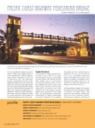
<strong>The</strong> <strong>Ernest</strong> F. <strong>Lyons</strong> replacement<br />
bridge is a 4600-ft-long, 31-span,<br />
precast segmental bridge built<br />
using the span-by-span method<br />
of construction. Photos: Jim<br />
Schneiderman, PCL.<br />
In July of 2003, PCL Civil Constructors<br />
Inc. (PCL) was the low bidder on<br />
a $46 million lump sum designbuild<br />
contract for the <strong>Ernest</strong> F. <strong>Lyons</strong><br />
<strong>Bridge</strong> <strong>Replacement</strong> project in Stuart,<br />
Florida. <strong>The</strong> main scope of this Florida<br />
Department of Transportation (FDOT)<br />
project was the construction of a new<br />
high-level segmental bridge over the<br />
Intracoastal Waterway in Martin County,<br />
Florida. <strong>The</strong> project site is located on<br />
Florida’s East Coast, approximately 45<br />
miles north of West Palm Beach.<br />
<strong>The</strong> new <strong>Ernest</strong> F. <strong>Lyons</strong> <strong>Bridge</strong> is a<br />
4600-ft-long, 31-span, two-lane, precast<br />
segmental bridge built using the spanby-span<br />
method of construction. With<br />
the exception of the first span, which<br />
is 100 ft long, all spans are 152 ft in<br />
length. Typical segments were 10 ft long,<br />
10 ft deep and 61 ft wide and weighed<br />
approximately 80 tons. Pier segments<br />
were split into two half-segments, each<br />
5 ft long, to reduce their weight for<br />
handling. A typical span consisted of<br />
15 precast segments that were posttensioned<br />
together using ten 19-strand<br />
tendons. Five tendons ran along each<br />
web wall. <strong>The</strong> spans were subsequently<br />
made continuous into six-span units.<br />
<strong>The</strong> 32 foundation units for the<br />
segmental bridge used between ten<br />
profile<br />
<strong>Ernest</strong> F. <strong>Lyons</strong> <strong>Bridge</strong> <strong>Replacement</strong> / Stuart, Florida<br />
Design Engineer: Parsons Transportation Group, Jacksonville, Fla.<br />
Peer Review Engineer: Corven Engineering, Tallahassee, Fla.<br />
Prime Contractor: PCL Civil Constructors Inc., Tampa, Fla.<br />
Ready Mix <strong>Concrete</strong>: Tarmac, West Palm Beach, Fla.<br />
Post-Tensioning: VSL, Springfield, Va.<br />
Substructure Formwork: Symons Corporation, Des Plaines, Ill.<br />
Awards: Florida Transportation Builder’s Association “Best in Construction” award in the Major <strong>Bridge</strong><br />
Category and an award of excellence from the Design-Build Institute of America (DBIA)<br />
36 | ASPIRE, Winter 2008
REPLACEMENT PROJECT<br />
by Jim Schneiderman,<br />
PCL Civil Constructors Inc.<br />
and fourteen 24-in. square prestressed<br />
concrete piles ranging in length from<br />
75 to 105 ft. <strong>The</strong> bridge piers consisted<br />
of a single pile cap and a single flared<br />
column. Column heights ranged from 12<br />
to 60 ft above the top of footing, thereby<br />
making the vertical clearance of the<br />
bridge 65 ft at the navigation channel<br />
per U.S. Coast Guard requirements.<br />
In addition to construction of the<br />
segmental bridge, the project scope<br />
included construction of two low-level<br />
AASHTO girder bridges. Each bridge<br />
consisted of ten 50-ft spans and was<br />
constructed to provide recreational<br />
access onto spoil islands within the<br />
project limits. <strong>The</strong> two-lane bridges<br />
consisted of 24-in. square prestressed<br />
concrete piles, cast-in-place concrete<br />
bent caps, AASHTO Type II beams, and<br />
a 50-ft-wide, 8.5-in.-thick cast-in-place<br />
concrete bridge deck.<br />
Additional improvements were also<br />
required adjacent to each of these small<br />
bridges. Specifically, 1600 ft of precast<br />
concrete sheet pile wall and 3500 tons<br />
of bank and shore riprap were installed<br />
on the approach roadways. Finally,<br />
over 2500 lin. ft of new roadway was<br />
constructed to connect these two new<br />
structures to the segmental bridge<br />
alignment.<br />
<strong>The</strong> final phase of the scope included<br />
extensive landscaping improvements, as<br />
well as demolition of the existing bascule<br />
bridge structure constructed in 1950. <strong>The</strong><br />
contract required all concrete portions of<br />
the existing bascule bridge to be removed<br />
and transported seven miles offshore into<br />
the Atlantic Ocean, where they were<br />
disposed of as an artificial reef.<br />
PCL subcontracted the design services<br />
for the project to Parsons Transportation<br />
Group and the project team received<br />
the Notice to Proceed on October 2,<br />
2003. <strong>The</strong> total project duration was<br />
1580 days, providing for a contract<br />
completion date of February 12, 2008.<br />
Precast <strong>Concrete</strong> Segmental / Florida Department of Transportation, Owner<br />
<strong>Bridge</strong> Description: 4600-ft-long, 31-span, precast segmental bridge built using the span-by-span method plus two low-level recreational access bridges<br />
Segment Formwork: Southern Forms Inc., Guild, Tenn.<br />
Erection Truss: DEAL, Udine, Italy<br />
Segment Lifter: Somerset Engineers and KWH Construction Corp., Vancouver, B.C., Canada<br />
Precaster for Low-Level <strong>Bridge</strong>s: Standard <strong>Concrete</strong> Products, Tampa Fla., a PCI-Certified Producer<br />
Structural Components: 501 precast concrete segments, 30 flared columns, and 32 foundation units with precast concrete seal slabs and ten<br />
to fourteen 24-in.-square prestressed concrete piles ranging in length from 75 to 105 ft for the main bridge and 24-in.-square prestressed concrete piles,<br />
CIP bent caps, AASHTO Type II beams, and CIP bridge deck for the low-level bridges<br />
<strong>Bridge</strong> Construction Cost: $46.5 million<br />
ASPIRE, Winter 2008 | 37
501 segments were cast at a rate of three per day.<br />
PCL was responsible for obtaining<br />
environmental permits for the project<br />
and no construction could begin until<br />
all permits had been obtained. Despite<br />
PCL’s aggressive efforts to obtain<br />
all environmental permits in a timely<br />
manner, the permitting process took<br />
two months longer than anticipated.<br />
<strong>The</strong> final permit was received in August<br />
2004, thereby allowing construction<br />
activities to begin.<br />
Hurricane Hazards<br />
On September 4, 2004, Hurricane<br />
Frances—a Category 2 storm—made<br />
landfall on the project site just weeks<br />
after construction had begun. <strong>The</strong><br />
jobsite sustained minimal wind damage<br />
and a fair amount of washouts to the<br />
existing roadway caused by rain and/<br />
or wave action. Shortly after the work<br />
resumed, Hurricane Jeanne—a Category<br />
3 storm—made landfall on September<br />
25, 2004. <strong>The</strong> official landfall location<br />
of Hurricane Jeanne was within 2 miles<br />
of Hurricane Frances; however the<br />
damages incurred due to Hurricane<br />
Jeanne were significantly greater than<br />
those caused by the previous storm.<br />
Despite these back-to-back hurricane<br />
events, the project team recovered<br />
quickly and proceeded with substructure<br />
production work.<br />
Foundation and substructure operations<br />
progressed uneventfully on the project<br />
between October 2004 and October<br />
2005. As the bottom elevation of all<br />
land foundations was well below the<br />
water table, land foundations were<br />
constructed using a mud seal and sheet<br />
pile shoring system that allowed crews<br />
to dewater the excavation for footing<br />
construction. Water foundations were<br />
constructed using a precast concrete<br />
seal slab that was hung from the piles<br />
and served as the bottom form for the<br />
footing concrete. Footing and column<br />
formwork systems were designed to<br />
withstand 10 ft of liquid head during<br />
concrete placement. By doing so, crews<br />
were able to place all columns in a single<br />
lift.<br />
Of the 32 foundation units on the<br />
project, 15 were located on land and<br />
17 were located in the water. All piling<br />
was driven using a Delmag D-46 diesel<br />
pile hammer with a Manitowac 4100W<br />
Series 2 crawler crane. 4100W Series 2<br />
cranes were also used in construction<br />
of the footings and columns on both<br />
land and water. In addition to the<br />
standard equipment required for landbased<br />
operations, water foundations<br />
also required the use of crane barges,<br />
material barges, and push boats to<br />
shuttle labor forces, materials, and<br />
equipment between land and water.<br />
On October 24, 2005, another<br />
hurricane, Hurricane Wilma—a Category<br />
1 storm—passed yet again over the<br />
project site. Fortunately, damage during<br />
this storm was not as severe as that<br />
caused by the first two hurricanes. <strong>The</strong><br />
project team made the necessary repairs<br />
and was back on track by November<br />
2005 making preparations to begin<br />
segment erection.<br />
PCL’s casting yard for the project<br />
was located in Fort Pierce, Florida,<br />
approximately 30 miles north of the<br />
A self-launching underslung truss was used to support the segments.<br />
Typical segments were 10 ft long, 10 ft deep,<br />
and 61 ft wide, weighing about 80 tons.<br />
project site. Three casting beds were<br />
used to construct the 501 segments<br />
for the project. Two casting beds were<br />
set up to construct typical segments,<br />
while a third bed was set up to be<br />
interchangeable for pier segments and<br />
expansion joint segments.<br />
Although the design compressive<br />
strength of the concrete for bridge<br />
segments was 5500 psi, transverse<br />
post-tensioning of the top slab could<br />
be performed once concrete had<br />
reached 2500 psi, thereby allowing the<br />
segment forms to be stripped. With<br />
the use of high early strength concrete,<br />
PCL was able to perform transverse<br />
post-tensioning and strip the forms<br />
approximately 12 hours after casting. By<br />
doing so, crews were able to cast one<br />
segment per day with each casting bed<br />
for a total of three segments per day<br />
(two typical segments and one pier or<br />
expansion joint segment). Although this<br />
rate of production is common for typical<br />
segments, it is quite an accomplishment<br />
for pier or expansion joint segments due<br />
to the large amount of reinforcing steel<br />
and post-tensioning hardware required<br />
in these segments.<br />
Segment Erection<br />
Due to shallow water depths on site and<br />
strict environmental permit conditions<br />
regarding protected seagrasses, PCL<br />
chose to erect the bridge segments<br />
using a top-down method. As a result,<br />
all segments were trucked individually<br />
from the casting yard in Fort Pierce to<br />
the project site.<br />
Load limit restrictions dictated the haul<br />
route for transporting the segments<br />
from the casting yard to the project<br />
site. In addition, transportation<br />
permits only allowed segments to<br />
be delivered between 9:00 p.m. and<br />
5:00 a.m. Due to these transportation
estrictions, PCL was only able to deliver<br />
six segments each night. In order to<br />
maintain production cycles, the project<br />
team designated an area on-site with<br />
sufficient room to store one complete<br />
span of segments. As soon as the<br />
transport crew had delivered enough<br />
segments to complete one span, the<br />
erection crew was ready to erect those<br />
segments. It was a delicate balancing<br />
act that required close coordination<br />
between the transport, segment storage,<br />
and erection crews.<br />
Also located within the on-site segment<br />
storage area was a temporary building<br />
constructed to store all bridge components<br />
that were sensitive to the elements.<br />
Specifically, this temporary structure<br />
provided storage for post-tensioning<br />
strand, cable grout, HDPE duct, and other<br />
miscellaneous but important components.<br />
Without any one of these components,<br />
segment erection would come to a halt.<br />
<strong>The</strong>refore, it was crucial to efficiently<br />
manage the limited storage area available<br />
while maintaining sufficient inventories of<br />
each of these components.<br />
<strong>The</strong> erection truss used by PCL during<br />
segment erection was a self-launching<br />
underslung truss. <strong>The</strong> truss was<br />
fabricated in Italy and assembled on<br />
the project site. To perform the topdown<br />
erection of segments, PCL used<br />
a specialized segment lifter. <strong>The</strong>se<br />
specialized pieces of equipment coupled<br />
with the methods of erection allowed<br />
crews to consistently erect one span of<br />
bridge every four shifts.<br />
<strong>The</strong> <strong>Ernest</strong> <strong>Lyons</strong> <strong>Bridge</strong> project was<br />
the first project to be constructed<br />
using FDOT’s new post-tensioning<br />
specification. Some of the requirements<br />
of this new specification included shear<br />
transfer devices on all steel pipes within<br />
the pier segments, duct couplers at each<br />
steel pipe connection of the split pier<br />
segments and more stringent pressure<br />
tests on each tendon prior to grouting.<br />
<strong>The</strong> segmental bridge was opened to<br />
traffic on September 18, 2006. Upon<br />
completion of the bridge, crews<br />
immediately began the final phase of<br />
the project including demolition of the<br />
<strong>The</strong> specialized lifter and erection<br />
truss allowed one span of bridge<br />
to be erected every four shifts.<br />
Each typical span consisted of 15<br />
segments post-tensioned together.<br />
existing bascule bridge. <strong>The</strong> project was<br />
officially completed and accepted by the<br />
FDOT on May 19, 2007, with a grand<br />
opening ceremony and many accolades<br />
from local residents.<br />
D e s p i t e n u m e r o u s c h a l l e n g e s<br />
encountered, the <strong>Ernest</strong> F. <strong>Lyons</strong> <strong>Bridge</strong><br />
<strong>Replacement</strong> project was completed<br />
within budget and more than 8 months<br />
ahead of the contract schedule. In<br />
2007, the project received the Florida<br />
Transportation Builder’s Association “Best<br />
in Construction” award in the Major<br />
<strong>Bridge</strong> Category. <strong>The</strong> project also went<br />
on to receive an award of excellence from<br />
the Design-Build Institute of America<br />
(DBIA). It is truly a bridge of which the<br />
concrete industry can be proud.<br />
_____________________<br />
Jim Schneiderman is Construction<br />
Manager with PCL Civil Constructors Inc.,<br />
Tampa, Florida.<br />
For more information on this or other<br />
projects, visit www.aspirebridge.org.<br />
Preserving Endangered Species<br />
This project was located in an aquatic<br />
preserve with the presence of an<br />
endangered species of seagrass and as<br />
a result, the environmental permitting<br />
requirements became quite involved. As<br />
a condition of the South Florida Water<br />
Management District (SFWMD) and U.S.<br />
Army Corps of Engineers (USACOE) permit<br />
applications, PCL was required to perform a<br />
seagrass survey to document the presence<br />
of seagrasses within the project limits. Due<br />
to the growing season of seagrass, this<br />
survey could only be performed during the<br />
month of August each year. As mentioned<br />
in the above article, the FDOT did not issue<br />
the Notice to Proceed for the project until<br />
October 2003. In an effort to expedite the<br />
permitting process, PCL performed the initial<br />
seagrass survey at their own risk during<br />
August 2003. Had PCL not performed the<br />
seagrass survey at this time, the permitting<br />
application could not have been completed<br />
until August of the following year.<br />
ASPIRE, Winter 2008 | 39
<strong>The</strong> Revised FDOT<br />
POST-TENSIONING SPECIFICATIONS<br />
by Clyde Ellis, VSL<br />
<strong>The</strong> <strong>Ernest</strong> F. <strong>Lyons</strong> <strong>Bridge</strong> is one of the first post-tensioned<br />
bridges in Florida to be constructed under the latest Florida Department<br />
of Transportation (FDOT) post-tensioning specifications. <strong>The</strong><br />
FDOT rewrote the state’s specifications into a five-part strategy with<br />
a goal of producing a design, construction, and maintenance environment<br />
that consistently produces durable post-tensioned bridges.<br />
<strong>The</strong> first part of the strategy requires the use of enhanced posttensioning<br />
systems. To ensure compliance, the FDOT approves all<br />
post-tensioning systems and lists them on the state’s Qualified Product<br />
List (QPL). <strong>The</strong> qualities that constitute an enhanced post-tensioning<br />
system include: a three-level system of corrosion protection;<br />
tendons placed within plastic ducts; positively sealed duct connections;<br />
prebagged and preapproved grout for post-tensioning tendons;<br />
post-tensioning tendons capped with permanent, heavy-duty plastic<br />
caps incorporating an O-ring seal; elastomeric coating over pour-back<br />
areas; as well as pressure testing of all post-tensioning tendon ducts.<br />
<strong>The</strong> second part requires all post-tensioning tendons to be<br />
completely filled with grout during construction. This requirement<br />
also includes the condition that all anchorages must be accessible<br />
for stressing, grouting, and inspection throughout all processes of<br />
installation and protection. To meet the third requirement of the<br />
strategy, all post-tensioning tendon anchors must have a minimum<br />
of four levels of corrosion protection. <strong>The</strong> fourth part states that the<br />
decks of post-tensioned bridges must be watertight. Finally, the fifth<br />
part of the requirements states that post-tensioned bridges must<br />
be designed to provide increased redundancy with multiple tendon<br />
paths using a greater number of smaller-sized tendons.<br />
On the <strong>Ernest</strong> F. <strong>Lyons</strong> <strong>Bridge</strong>, the post-tensioning system, supplied<br />
by VSL, has anchorages with galvanized protection and ducts<br />
made of UV resistant-plastic to meet the new specifications. To<br />
ensure proper grouting, the anchorages have dual inspection ports<br />
through which inspectors use a borescope to determine visually if<br />
the anchorages are completely filled with grout. <strong>The</strong> system utilizes<br />
a combination of mechanical couplers and/or heat-shrink sleeves to<br />
create water and airtight connections. All admixtures used to grout<br />
the tendons are premixed and prebagged with the cement.<br />
Florida’s specifications for post-tensioning are available at Section<br />
463 of their Standard Specifications for Road and <strong>Bridge</strong> Construction<br />
(www.dot.state.fl.us/specificationsoffice/2007BK/TOC.htm).<br />
____________________<br />
Clyde Ellis is Branch Manager with VSL’s Washington, D.C., office.<br />
Q<br />
A<br />
Edison <strong>Bridge</strong>, Fort Myers, Florida<br />
How do you connect<br />
the rebar?<br />
Use the…<br />
NMB<br />
Splice-Sleeve ®<br />
System.<br />
How to do it in Precast…<br />
cross-section<br />
Q<br />
A<br />
How is the moment connection made?<br />
All you need is an emulative detail,<br />
reconnect the concrete and rebar.<br />
Mill Street <strong>Bridge</strong>, Epping, New Hampshire<br />
SPLICE SLEEVE NORTH AMERICA, INC.<br />
<br />
<br />
WWW.SPLICESLEEVE.COM<br />
11003_SPLICE_.5bridge_win08.indd 1<br />
40 | ASPIRE, Winter 2008<br />
11/30/07 10:51:14 AM


