

The I-15 Beck STreeT BrIdgeS - Aspire - The Concrete Bridge ...
The I-15 Beck STreeT BrIdgeS - Aspire - The Concrete Bridge ...
The I-15 Beck STreeT BrIdgeS - Aspire - The Concrete Bridge ...

You also want an ePaper? Increase the reach of your titles
YUMPU automatically turns print PDFs into web optimized ePapers that Google loves.
Designed to<br />
remain fully functional<br />
after the anticipated<br />
maximum seismic event.<br />
<strong>The</strong> $1<strong>15</strong> million I-<strong>15</strong> widening project<br />
from 500 North in Salt Lake City, Utah,<br />
to the I-2<strong>15</strong> junction in Davis County,<br />
added 4 miles of northbound and<br />
southbound express lanes to I-<strong>15</strong>. As<br />
part of the design-build project, the<br />
existing six-lane <strong>Beck</strong> Street <strong>Bridge</strong><br />
was removed and replaced with twin,<br />
four-span bridges to carry a total of<br />
10 lanes of traffic on I-<strong>15</strong>. <strong>The</strong> bridge<br />
replacement, including additional<br />
lanes, eased the heavily used commuter<br />
route.<br />
<strong>The</strong> northbound and southbound<br />
I-<strong>15</strong> <strong>Beck</strong> Street <strong>Bridge</strong>s are the<br />
Utah Department of Transportation’s<br />
(UDOT’s) first bridges designed to<br />
remain fully functional after the<br />
anticipated maximum seismic event.<br />
At the time of construction, they also<br />
used the longest precast, prestressed<br />
concrete girders ever fabricated and<br />
erected in the United States.<br />
<strong>The</strong> I-<strong>15</strong><br />
<strong>Beck</strong> Street <strong>Bridge</strong>s<br />
A Tectonic Shift in <strong>Bridge</strong> Design<br />
by Corin Piacenti, Parsons Corporation<br />
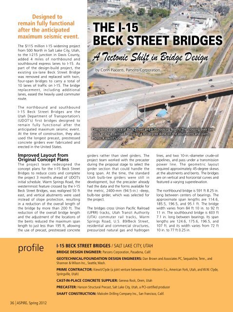
Completed structure at <strong>Beck</strong> Street and I-<strong>15</strong> (looking North) <strong>The</strong> crossing over two<br />
roads and the railroad, required a 45-degree skew on the abutments and piers.<br />
Photo: Kiewit/Clyde.<br />
Improved Layout from<br />
Original Concept Plans<br />
<strong>The</strong> project team redesigned the<br />
concept plans for the I-<strong>15</strong> <strong>Beck</strong> Street<br />
<strong>Bridge</strong>s to reduce costs and complete<br />
the project 3 months ahead of UDOT’s<br />
initial schedule. Warm Springs Road, the<br />
westernmost feature crossed by the I-<strong>15</strong><br />
<strong>Beck</strong> Street <strong>Bridge</strong>s, was realigned 50 ft<br />
east, and vertical abutments were used<br />
instead of slope protection, resulting<br />
in a reduction of the overall length of<br />
the bridge by more than 200 ft. <strong>The</strong><br />
reduction of the overall bridge length<br />
and the adjustment of the locations of<br />
the bents reduced the maximum span<br />
length to just less than 195 ft, allowing<br />
the use of precast, prestressed concrete<br />
girders rather than steel girders. <strong>The</strong><br />
project team worked with the precaster<br />
during the proposal stage to select the<br />
girder section that could handle the<br />
long span. At the time, the standard<br />
Utah bulb-tee girders were still in<br />
development, but the precaster already<br />
had the data and the forms available for<br />
the metric, 2400-mm (94.5-in.) -deep,<br />
bulb-tee girder, which was selected for<br />
the project.<br />
<strong>The</strong> bridges cross Union Pacific Railroad<br />
(UPRR) tracks, Utah Transit Authority<br />
(UTA) commuter rail tracks, Warm<br />
Springs Road, U.S. 89/<strong>Beck</strong> Street,<br />
residential and commercial structures,<br />
pressurized natural gas and hydrogen<br />
lines, and two 10-in.-diameter crude-oil<br />
pipelines, and pass under a transmission<br />
power line. <strong>The</strong> geometric layout<br />
required approximately 45-degree skews<br />
at the abutments and bents. <strong>The</strong> bridges<br />
are on vertical and horizontal curves and<br />
featured a varying superelevation.<br />
<strong>The</strong> northbound bridge is 591 ft 8.25 in.<br />
long between centers of bearings. <strong>The</strong><br />
approximate span lengths are 114.6,<br />
185.5, 196.5, and 95.1 ft. <strong>The</strong> bridge<br />
width varies from 84 ft 10 in. to 92 ft<br />
11 in. <strong>The</strong> southbound bridge is 603 ft<br />
7.1 in. long between bearings. Its span<br />
lengths are 124.6, 175.6, 196.5, and<br />
107 ft. and its width varies from 72 ft<br />
10 in. to 77 ft 0.25 in.<br />
profile<br />
I-<strong>15</strong> <strong>Beck</strong> Street <strong>Bridge</strong>s / Salt Lake City, Utah<br />
bridge design Engineer: Parsons Corporation, Pasadena, Calif.<br />
GEOTECHNICAL/FOUNDATION DESIGN ENGINEERS: Dan Brown and Associates PC, Sequatchie, Tenn., and<br />
Shannon & Wilson Inc., Seattle, Wash.<br />
prime contractor: Kiewit/Clyde (a joint venture between Kiewit Western Co., American Fork, Utah, and W.W. Clyde,<br />
Springville, Utah)<br />
CAST-IN-PLACE CONCRETE SUPPLIER: Geneva Rock, Orem, Utah<br />
precaster: Hanson Structural Precast, Salt Lake City, Utah, a PCI-certified producer<br />
SHAFT CONSTRUCTION: Malcolm Drilling Company Inc., San Francisco, Calif.<br />
36 | ASPIRE, Spring 2012
<strong>The</strong> use of long precast concrete girders was<br />
vital in accelerating the schedule, minimizing impact<br />
to the railroads, and reducing costs.<br />
guide the girder designs. <strong>The</strong> girders<br />
required 8500 psi compressive strength<br />
concrete to reach the desired span<br />
length. <strong>The</strong> specified strength of the<br />
concrete at prestress transfer was 6500<br />
psi. <strong>The</strong> girder bearings are 5¼-in.-thick<br />
reinforced elastomeric pads. <strong>The</strong> use of<br />
the long precast, prestressed concrete<br />
girders was vital in accelerating the<br />
schedule, minimizing impact to the<br />
railroads, and reducing costs.<br />
Use of Precast Elements<br />
<strong>The</strong> bridges use 194-ft 5-in.-long bulbtee<br />
girders with shipping weights of<br />
approximately 242 kips. <strong>The</strong> 92 girders<br />
have a depth of 7 ft 10½ in. and are<br />
flared in the end spans to accommodate<br />
a varying roadway width. <strong>The</strong> centerto-center<br />
spacing of the girders varies<br />
from approximately 6 ft 9 in. to 7 ft 7<br />
in. Steel was used for the intermediate<br />
diaphragms. <strong>The</strong> girders are heavily<br />
pretensioned, using up to sixty-eight<br />
0.6-in.-diameter prestressing strands.<br />
<strong>The</strong> total jacking force was 2988 kips—<br />
791 kips in the 18 harped strands and<br />
2197 kips in the 50 straight strands. <strong>The</strong><br />
engineer used prestress bed capacity<br />
information from the precaster to<br />
<strong>The</strong> girders were shipped 18 miles<br />
to the construction site supported<br />
on each end by trailers specifically<br />
constructed for their transport. <strong>The</strong>y<br />
were then lifted from the trailers and<br />
walked into place using two 250-ton<br />
crawler cranes. <strong>The</strong> precaster placed<br />
three monostrands in each edge of<br />
the top flanges of the girders. <strong>The</strong>se<br />
helped to improve stability and mitigate<br />
tensile stresses in the girders’ flanges<br />
during stripping, shipping, and erection.<br />
<strong>The</strong> monostrands eliminated the need<br />
for external bracing and were cut to<br />
detention them following erection.<br />
Keeping with UDOT’s commitment<br />
to incorporating accelerated bridge<br />
construction elements during design,<br />
Each girder weighed up to 242 kips.<br />
Photo: Hanson Structural Precast.<br />
partial-depth precast concrete panels<br />
were used in the 8½-in.-thick composite<br />
bridge deck. <strong>The</strong> 3.5-in.-thick, precast<br />
concrete panels, ranging from 3 ft 7<br />
in. to 4 ft 7¾ in. wide and from 3 to<br />
8 ft long, span between the girders<br />
and serve as stay-in-place forms for<br />
the bridges’ cast-in-place concrete<br />
deck. <strong>The</strong>se allowed the project to<br />
avoid installation and removal of forms<br />
over the railroad and was estimated<br />
to have saved an additional 6 to 8<br />
weeks of construction time. <strong>The</strong> design<br />
compressive strength of the panel<br />
concrete was 5000 psi.<br />
A precast, prestressed concrete bulb-tee girder during transport to the project. At 194 ft<br />
5 in., the girders were the longest used in the United States at the time. Photo: Hanson<br />
Structural Precast.<br />
TWIN, PRECAST, PRESTRESSED CONCRETE BULB-TEE GIRDER BRIDGES WITH COMPOSITE, CAST-IN-PLACE<br />
CONCRETE DECK ON PRECAST CONCRETE DECK PANELS / UTAH DEPARTMENT OF TRANSPORTATION, OWNER<br />
DEEP SOIL MIXING: Hayward-Baker AGC, Odenton, Md.<br />
bridge description: Twin, four-span precast, prestressed concrete bulb-tee girder bridges with partial-depth precast concrete deck panels and<br />
with cast-in-place concrete piers, abutments, wing walls, and foundations<br />
structural components: Ninety-two 7-ft 10½-in.-deep bulb-tee girders with a maximum girder length of 194 ft 5 in., 48,333 ft 2 of precast<br />
3½-in.-thick deck panels made composite with 5-in.-thick cast-in-place concrete, and twenty-four 9-ft 2-in.-diameter drilled shafts with a maximum depth<br />
of 122 ft<br />
awards: 2011 PCI Design Awards, Honorable Mention, Main Spans Greater than <strong>15</strong>0 Ft, 2011 American Council of Engineering Companies, Utah<br />
Chapter, Structural Systems Grand Award; 2010 Roads & <strong>Bridge</strong>s, No. 9 Top Ten Road Projects; 2010 Utah Department of Transportation, Urban Project of<br />
the Year.<br />
ASPIRE, Spring 2012 | 37
Durability and Maintainability<br />
<strong>The</strong> project team evaluated and selected material alternatives based on their ability to meet<br />
and exceed the project criteria, constructability, cost, aesthetic value, maintainability, and<br />
durability. Maintenance-free or low-cost maintenance components and a design that enabled<br />
easy access for maintenance crews were prime objectives. <strong>The</strong> design incorporated several<br />
components with specific durability and maintainability benefits, including:<br />
• Precast, prestressed concrete girders that eliminate the need for painting.<br />
• Partial-depth precast concrete deck panels that provide a PCI-certified, plant-produced,<br />
dense concrete in the bottom half of the bridge deck.<br />
• Polymer concrete deck overlay that has proven highly effective in Utah’s environment for<br />
at least <strong>15</strong> years.<br />
• Deck designed with a ½-in.-thick sacrificial wearing layer and design for a 40 lb/ft 2<br />
future wearing surface.<br />
• Expansion joints only at abutments; no expansion joints at piers.<br />
• UDOT maximum amount of fly ash in the concrete mixtures.<br />
• Epoxy-coated reinforcement in all elements except the drilled shafts and piles.<br />
Seismic Design Category D with a<br />
ductility demand equal to the maximum<br />
allowed. For a bridge with a performance<br />
level defined as “operational,” UDOT<br />
requires that the damage sustained must<br />
be negligible and full service available<br />
for all vehicles after the inspection and<br />
clearance of debris. Any damage to<br />
the bridge must be repairable, without<br />
interruption to traffic.<br />
<strong>Bridge</strong>s Open to Traffic<br />
After 6 months of design and 20<br />
months of construction, the I-<strong>15</strong> <strong>Beck</strong><br />
Street <strong>Bridge</strong>s were completed and<br />
opened to traffic on August 16, 2010.<br />
With the completion of the project, the<br />
commute from and to the communities<br />
north of Salt Lake City was eased due to<br />
the increased capacity of I-<strong>15</strong>.<br />
__________<br />
Corin Piacenti is a structure design<br />
engineer with Parsons Corporation’s South<br />
Jordan office, near Salt Lake City, Utah.<br />
For additional photographs or<br />
information on this or other projects,<br />
visit www.aspirebridge.org and open<br />
Current Issue.<br />
<strong>The</strong> girders are 7 ft 10½ in. deep and are<br />
shown in the fabrication plant. Photo:<br />
Hanson Structural Precast.<br />
Seismic Design<br />
<strong>The</strong> <strong>Beck</strong> Street <strong>Bridge</strong>s are the first<br />
UDOT structures to be designed with<br />
the performance level category of<br />
“operational” using MCEER/ATC-49<br />
Recommended LRFD Guidelines for<br />
the Seismic Design of Highway <strong>Bridge</strong>s<br />
and the UDOT Structures Design<br />
Manual. UDOT classifies these bridges<br />
as “critical” because north and south<br />
mobility is constricted at this location<br />
by I-<strong>15</strong>, U.S. 89, and the UPRR and<br />
UTA tracks. <strong>The</strong> bridges provide a vital<br />
connection between Salt Lake County<br />
and Davis County.<br />
Structures that UDOT classifies as<br />
“critical” must remain operational after<br />
the maximum considered earthquake<br />
(MCE). <strong>The</strong> MCE is defined as the<br />
earthquake response corresponding<br />
to a 2% probability of exceedance (PE)<br />
in 50 years (a return period of 2500<br />
years), which is also equivalent to the<br />
MCEER 3% PE in 75 years. Per UDOT<br />
seismic design requirements, “critical”<br />
bridges must meet the displacement<br />
and detailing requirements for<br />
<strong>The</strong> abutment is isolated from the<br />
approach embankment to reduce<br />
loading effects from the lateral spread<br />
of the embankment in an earthquake.<br />
<strong>The</strong> abutment embankment is protected<br />
through the use of deep-soil mixing.<br />
Column reinforcement cage in a 9-ft<br />
2-in.-diameter drilled shaft. Photo:<br />
Kiewit/Clyde.<br />
Precast concrete partial-depth deck<br />
panels provide a high-performance<br />
concrete, stay-in-place form and all of<br />
the positive moment reinforcement<br />
between beams in the bottom of the<br />
8½-in.-thick composite deck. Photo:<br />
Hanson Structural Precast.<br />
Completed twin bridges at <strong>Beck</strong> Street<br />
and I-<strong>15</strong> (looking North-East). Photo:<br />
Kiewit/Clyde.<br />
38 | ASPIRE, Spring 2012


