Weathermatic SmartWire 2-Wire Controller Owner's ... - Irrigation Direct
Weathermatic SmartWire 2-Wire Controller Owner's ... - Irrigation Direct
Weathermatic SmartWire 2-Wire Controller Owner's ... - Irrigation Direct

Create successful ePaper yourself
Turn your PDF publications into a flip-book with our unique Google optimized e-Paper software.
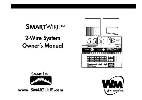
SLM48DM 48-zone<br />
2-wire decoder module<br />
<br />
2-<strong>Wire</strong> System<br />
Owner’s Manual<br />
STATUS<br />
ZONE<br />
PROGRAM<br />
ZONE<br />
PGM<br />
RUN<br />
SELECT<br />
MODE<br />
SLM48DM 2-<strong>Wire</strong> Module<br />
R B<br />
POWER 1<br />
MASTER VALVE<br />
R B<br />
2<br />
R B<br />
3<br />
R<br />
B<br />
PROGRAM<br />
PORT<br />
®
2-<strong>Wire</strong> System Owner’s Manual<br />
®<br />
Contents<br />
1.1 System Components.............................................................. 3<br />
1.2 How It Works....................................................................... 3<br />
1.3 Installing the SLM48DM 2-<strong>Wire</strong> Decoder Module.................... 4<br />
1.4 Programming the Decoders.................................................... 4<br />
1.5 Planning Your 2-<strong>Wire</strong> Layout.................................................. 6<br />
1.6 Lightning Protection.............................................................. 8<br />
1.7 Troubleshooting...................................................................11<br />
1.8 Special System Features...................................................... 12<br />
1.9 Electrical Specifications....................................................... 12<br />
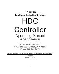
SLM48DM 48-zone<br />
2-wire decoder module<br />
STATUS<br />
ZONE<br />
PROGRAM<br />
ZONE<br />
PGM<br />
RUN<br />
SELECT<br />
MODE<br />
SLM48DM 2-<strong>Wire</strong> Module<br />
Zone number<br />
up/down<br />
Top light=<br />
program mode<br />
Bottom light=<br />
run mode<br />
Switches<br />
between<br />
program and<br />
run modes<br />
Program<br />
selected<br />
zone number<br />
to connected<br />
decoder/<br />
clear errors<br />
Program<br />
status light<br />
(green=success,<br />
red=error)<br />
Master valve<br />
R B<br />
POWER 1<br />
MASTER VALVE<br />
Power from<br />
“Hot” post<br />
R B<br />
2<br />
R B<br />
3<br />
R<br />
B<br />
PROGRAM<br />
PORT<br />
2-wire path terminals<br />
R=Red wire<br />
B=Black wire<br />
Decoder<br />
Programming<br />
Ports<br />
2
1.1 System Components<br />
®<br />
SLM48DM 48-zone 2-wire decoder module<br />
SLDEC1 Single-zone decoder<br />
SLDEC2 Two-zone decoder<br />
SLDEC4 Four-zone decoder<br />
SLGDT Lightning arrestor for surge protection<br />
SLCAM Clamp-on Amp Meter<br />
SLCONN Specialty <strong>Wire</strong> Connector<br />
SLWIRE 2-conductor, jacketed UL/UF approved for direct burial<br />
1.2 How it Works<br />
A decoder is installed at each valve box to activate the valves. Each<br />
decoder has a unique address which identifies it to the <strong>Weathermatic</strong><br />
SLM48DM 2-wire programming module installed in any SL1600 SmartLine®<br />
controller. The SLM48DM 2-wire decoder module broadcasts<br />
a command to activate on a certain address. All the decoders on the<br />
2-wire system “decode” the message but only the appropriate decoder<br />
responds and turns the attached valve on or off. The decoder responds<br />
back to the decoder module with a status message.<br />
The advantages of a <strong>Smart<strong>Wire</strong></strong> system include cost savings from<br />
reduction in copper wire usage and corresponding trenching, simplicity<br />
of wiring and troubleshooting and ease of expansion when additional<br />
zones are needed. <strong>Weathermatic</strong> <strong>Smart<strong>Wire</strong></strong> 2-<strong>Wire</strong> allows for<br />
connection of up to 3 separate 2-wire paths to simplify installation on<br />
larger projects. <strong>Smart<strong>Wire</strong></strong> is a member of the SmartLine® family of<br />
water management products offering automated, on-site water management.<br />
<br />
2-<strong>Wire</strong> System Owner’s Manual<br />
1.3 Installing the SLM48DM 2-<strong>Wire</strong> Decoder Module<br />
The SLM48DM 2-<strong>Wire</strong> Decoder Module permits use of any SL1600<br />
controller for 2-wire installation. The SL1600 will display 48 programmable<br />
zones when the SLM48DM is installed. You cannot exceed a<br />
total of 48 zones.<br />
• Step 1: Turn off the power to the SmartLine® <strong>Controller</strong>.<br />
• Step 2: Remove any previously installed zone modules and insert the<br />
SLM48DM into the far left side module slots in your controller.<br />
• Step 3: Disconnect the transformer’s green grounding wire from the<br />
terminal strip and cover exposed wire with a wire nut. This step is<br />
REQUIRED for <strong>Smart<strong>Wire</strong></strong> lightning protection to work properly.<br />
• Step 4: Connect the provided power wire from the Power terminal on<br />
the SLM48DM to the controller Hot Post.<br />
• Step 5 (optional): If you are using a master valve or pump start<br />
relay, and it is more convenient to wire to these devices at a location<br />
not near the controller, you can connect a wire (provided) from the<br />
master valve terminal on the SLM48DM to the P/MV terminal on<br />
the SL1600 controller as shown in the illustration. If you choose this<br />
method of wiring, you will need to program a decoder as Zone 99<br />
for use with the pump start relay or master valve. If it is convenient<br />
to wire the devices directly to the P/MV terminal on the controller, no<br />
wire link is needed between the P/MV terminal and SLM48DM.<br />
• Step 6: Re-connect power to the controller. You are ready to program<br />
your decoders. The SLM48DM will perform a “power-up self test” at<br />
initial power-up. The power-up self test will confirm the integrity of the<br />
processor and will test the display and all LEDs to make sure they are<br />
working. A successful test will terminate with two dashes “– –” in the<br />
display.<br />
3
Master Valve<br />
(Zone 99)<br />
2-<strong>Wire</strong> System Owner’s Manual<br />
SmartLine ® <strong>Controller</strong><br />
Green Ground <strong>Wire</strong><br />
P/MV<br />
<strong>Wire</strong><br />
(Provided)<br />
Power<br />
<strong>Wire</strong><br />
(Provided)<br />
SLDEC1<br />
SLDEC1<br />
SLDEC2<br />
SLM48DM<br />
Hot Post<br />
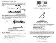
1.4 Programming the Decoders<br />
Step 1: Map out your<br />
valve and decoder locations.<br />
See Section 1.5.<br />
Step 2: Program all your<br />
decoders at the SmartLine®<br />
controller. You<br />
will need to mark each<br />
decoder with a pen<br />
(included) to record the<br />
zone number assigned<br />
to each valve. Note the<br />
adjacent chart of valve<br />
wire colors for each<br />
decoder:<br />
• Each decoder will<br />
have RED and BLACK<br />
wires. These are<br />
the wires that will<br />
1-Valve Decoder<br />
red<br />
black<br />
2-Valve Decoder<br />
red<br />
black<br />
4-Valve Decoder<br />
red<br />
black<br />
orange (1)<br />
white (com)<br />
yellow (2)<br />
orange (1)<br />
white (com)<br />
blue (4)<br />
green (3)<br />
yellow (2)<br />
orange (1)<br />
white (com)<br />
connect to the 2-wire path. The RED and BLACK are also the wires<br />
that you will insert in the Programming Ports on the SLM48DM to<br />
program the decoder.<br />
• The wires on the other end of each decoder are for connection to<br />
your valves.<br />
1-Valve Decoder: WHITE wire for the common and ORANGE wire<br />
for valve one.<br />
2-Valve Decoder: Common is WHITE; ORANGE is valve one and<br />
YELLOW is valve two.<br />
4-Valve Decoder: Common is WHITE; ORANGE is valve one;<br />
YELLOW is valve two; GREEN is valve three and BLUE is valve four.<br />
®<br />
4
®<br />
Decoder Programming Steps:<br />
• Use the SLM48DM mode button to select the PGM programming<br />
position.<br />
• Insert the RED and BLACK wires on the decoder in the Programming<br />
Ports on the SLM48DM (RED to RED, BLACK to BLACK).<br />
• Use up/down arrow buttons to select the zone number to be programmed.<br />
• Push Program Zone button to select the zone showing in the display<br />
window. Note: When you are programming a multi-valve decoder,<br />
the display will only show the zone number for the first zone to be<br />
assigned to that decoder. The remaining zones in the decoder are<br />
automatically assigned in sequential numerical order.<br />
• A GREEN status light will confirm your selection.<br />
• If programming is not successful, a RED status light will flash and an<br />
error code will be shown on the display. See Troubleshooting for<br />
description of error codes.<br />
• Mark the zone number programmed on the decoder. Note: If you<br />
are using a multi-valve decoder, the decoder will record the zone<br />
selected in the order previously noted for wire colors. For example, if<br />
you are using the 4-valve decoder, the first zone programmed will be<br />
Orange, the second Yellow and so on. Mark the zone number on the<br />
decoder for reference during field installation. You should also mark<br />
all zone numbers on your valve layout plan for reference during<br />
installation of the decoders.<br />
• After the decoders are connected to the valves, use the Mode button<br />
on the SLM48DM to place the decoder programmer in the Run position.<br />
The Green status light will confirm that the system is ready for<br />
operation. If the light is Red, refer to the Troubleshooting guide.<br />
• If you are using a master valve on your system, be sure to program it<br />
as zone 99 in the SLM48DM using a 1-valve decoder.<br />
<br />
2-<strong>Wire</strong> System Owner’s Manual<br />
SLM48DM RUN Mode<br />
• The program status LED will be GREEN.<br />
• After a program is complete, the SLM48DM display will show any malfunctioning<br />
zones. If more than one zone is malfunctioning, each zone<br />
along with the corresponding error code will be displayed sequentially<br />
in a repeating loop. The Program Zone button will clear each error code<br />
as it is displayed. See Troubleshooting for fault code descriptions.<br />
Programming Zones on your SmartLine® <strong>Controller</strong><br />
After the 2-wire installation and decoder programming is complete, you<br />
can use the SmartLine® controller to establish the watering schedule for<br />
all zones. The normal SL1600 programming convention applies to the<br />
<strong>Smart<strong>Wire</strong></strong> system.<br />
5
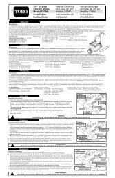
1.5 Planning Your 2-<strong>Wire</strong> Layout<br />
2-<strong>Wire</strong> System Owner’s Manual<br />
The <strong>Smart<strong>Wire</strong></strong> SLM48DM 2-<strong>Wire</strong> Decoder Module allows you to<br />
have several options in cable routing to determine the most efficient<br />
2-wire layout for your project. You can connect as many as three 2-wire<br />
runs. Maximum decoder to valve distance is 100 feet (30.5m).<br />
Each 2-wire run can be laid out in Straight Run, Complete Loop, Star, or<br />
Combination configurations as shown to the right.<br />
It is suggested that a continuous loop be laid out around the site. This<br />
usually follows the main water lines. The loop will start at the Smart-<br />
Line® controller and continue around the site and then return to the<br />
controller. This provides the best communication and power path for the<br />
system. The loop provides a redundant path for the power and signal<br />
allowing the system to continue operation if the loop is cut.<br />
Branches can come off the main loop and they do not need to be<br />
looped back to the main trunk line. These branches can be other loops,<br />
stars or single dead-end lines. The system will work with most wiring<br />
configurations if the wire length requirements are met. (Note: Keep<br />
BLACK to BLACK and RED to RED when wiring the communication wire.)<br />
Attaching Components<br />
• Twist wires together and secure with the SLCONN metal block wire<br />
connector.<br />
• Encapsulate the metal block inside the 3M DBR type, grease filled<br />
waterproof connector. Use of a connector is required for all connections<br />
between the 2-wire path and the decoders.<br />
• Use the appropriate connector for the wire size being used.<br />
• Adhere to all local and national building and electrical codes.<br />
Suggested <strong>Wire</strong> Details<br />
Straight<br />
Run<br />
Complete<br />
Loop<br />
Star<br />
SLM48DM<br />
Decoder<br />
SLM48DM<br />
Last<br />
Decoder<br />
Last<br />
Decoder<br />
Water Source<br />
Decoder<br />
Decoder<br />
Main Line<br />
Decoder<br />
SLM48DM<br />
Last Decoder<br />
Decoder<br />
®<br />
Last<br />
Decoder<br />
Last<br />
Decoder<br />
Last<br />
Decoder<br />
Combination SLM48DM Last<br />
Decoder<br />
6
®<br />
Wiring Sizes<br />
Straight line configuration, i.e. wire distance to the furthest decoder, no<br />
loop:<br />
<strong>Wire</strong> Size (Gauge) #18 #16 #14 #12<br />
<strong>Wire</strong> Length (ft) 1,000 2,000 4,000 6,000<br />
<strong>Wire</strong> Length (m) 305 610 1,210 1,829<br />
Loop configuration, i.e. wire distance to the furthest decoder in the loop:<br />
<strong>Wire</strong> Size (Gauge) #18 #16 #14 #12<br />
<strong>Wire</strong> Length (ft) 2,000 4,000 10,000 10,000<br />
<strong>Wire</strong> Length (m) 610 1,210 3,048 3,048<br />
Maximum total wire path length is 10,000 ft. (3,048 m).<br />
1 Station<br />
<br />
2-<strong>Wire</strong> System Owner’s Manual<br />
SLCONN<br />
Waterproof<br />
wiring connector<br />
To SLM48DM<br />
2 Station<br />
Common<br />
<strong>Wire</strong><br />
Finish<br />
Grade<br />
Valve Box<br />
Decoder<br />
SLCONN<br />
Waterproof<br />
wiring<br />
connectors<br />
4 Station<br />
2-<strong>Wire</strong> path<br />
Expansion<br />
Coil<br />
Common<br />
<strong>Wire</strong><br />
Expansion<br />
Coil<br />
Valve Box Detail<br />
Solenoid<br />
Valve<br />
Gravel<br />
7<br />
<strong>Weathermatic</strong> recommends the use of SLWIRE cable specifically designed<br />
for an irrigation control system and complying with the following<br />
specifications:<br />
• Conductors must be soft drawn, annealed, solid copper conforming<br />
to ASTM 33.<br />
• Conductor insulation must be 4/64-inch thick polyvinyl chloride<br />
(PVC) conforming to UL #493.<br />
• The two insulated conductors laid in parallel and encased in a
2-<strong>Wire</strong> System Owner’s Manual<br />
single outer jacket of 3/64-inch thick, high-density, sunlight resistant<br />
polyethylene conforming to ICEA S-61-402 and NEMA WC5, having<br />
a minimum wall thickness of .045-inch.<br />
• The two conductors must be color-coded: normally one conductor<br />
red and the other black. Both conductors shall be the same size.<br />
• The following models meet the above specifications for direct burial<br />
cable: <strong>Weathermatic</strong> SLWIRE12; <strong>Weathermatic</strong> SLWIRE14.<br />
1.6 Lightning Protection<br />
<strong>Weathermatic</strong> SLGDT gas discharge tube lightning arrestors must be<br />
used on all 2-wire grids. The SLGDT lightning arrestor attaches directly<br />
to the 2-wire system and helps dissipate static electricity generated by a<br />
nearby lightning strike. While <strong>Weathermatic</strong> components have lightning<br />
arresting features, the SLGDT provides an extra measure of protection.<br />
Features<br />
SLGDT Lightning Arrestor<br />
• Protects the 2-wire system from excessive<br />
static charges created by a lightning strike.<br />
• Sealed and impervious to moisture, salts,<br />
fertilizers and mild chemicals. Can be<br />
buried directly in the soil.<br />
• Shock resistant<br />
• Freeze/heat resistant (-20° to 60° C)<br />
• No electrical contact with the soil<br />
• Each Lightning Arrestor protects a 300 foot radius<br />
Electrical Specifications<br />
• Requires no power from the 2-wire system<br />
• Can only be connected to <strong>Smart<strong>Wire</strong></strong> 2-wire systems<br />
8<br />
SmartLine®<br />
SL1600<br />
<strong>Controller</strong><br />
with<br />
SLM48DM<br />
2<br />
600’ Max<br />
1<br />
600’ Max<br />
Decoder<br />
Lightning Arrestor<br />
2-<strong>Wire</strong> path<br />
Procedures for Installation<br />
• Connect the RED and BLACK lead wires to the 2-wire system RED<br />
and BLACK wires.<br />
• Attach the GREEN ground wire to Earth Ground (Grounding Requirements<br />
below)<br />
• Use only DBY or DBR 3M Type waterproof connectors encapsulating<br />
a twisted wire connection inside a metal block (SLCONN included).<br />
• For maximum protection, place an SLGDT every 600 feet along the<br />
2-wire system. (Example 1 in graphic above.)<br />
• One SLGDT should be within 25 ft of the host SmartLine® controller.<br />
(Example 2 in graphic above.)<br />
• A single stub line must not exceed 50 feet without an SLGDT lightning<br />
arrestor. (Example 3 in graphic above.)<br />
• An SLGDT lightning arrestor must also be placed at the end of the 2-<br />
wire run that is the maximum distance from the SmartLine® controller,<br />
or if looped, at the point of maximum distance from the SmartLine®<br />
controller. (Example 4 in graphic above.)<br />
1<br />
®<br />
50’ Max<br />
4<br />
3
®<br />
Ground Detail #1: SLGDT with single ground rod<br />
<br />
2-<strong>Wire</strong> System Owner’s Manual<br />
Ground Detail #2: SLGDT with Triangular Grid<br />
#8 AWG Bare<br />
Copper <strong>Wire</strong><br />
SLGDT<br />
SLCONN<br />
2-<strong>Wire</strong> Path<br />
CADWELD<br />
#8 AWG Bare<br />
Copper<br />
<strong>Wire</strong><br />
CADWELD<br />
8' Copper<br />
Clad Ground<br />
Rod<br />
6" Valve Box<br />
8' Minimum<br />
Grounding Requirements<br />
• The GREEN ground wire must be attached to a #8 solid bare copper<br />
wire using the included SLCONN wire connector. Connect the bare<br />
ground wire to a grounding circuit with 12 Ohms or less resistance to<br />
earth ground, measured with a ground resistance meter or Megger.<br />
• A grounding circuit is comprised of 4 major components:<br />
o Ground Rod(s) and/or Plate(s).<br />
o Ground Conductor.<br />
o Exothermic or Cadmium Weld connections.<br />
o Soil and/or Ground Enhancement Materials.<br />
• Ground Rods/Plates must be installed in a 6” min. valve box, 6”<br />
below grade or below frost line, located within an irrigated zone to<br />
maintain soil moisture and maximum ground performance.<br />
9<br />
2-<strong>Wire</strong> path<br />
• Ground Rods shall be UL listed “copper clad”, 5/8” minimum diameter,<br />
8’ of length, and must meet the requirements of NEC article 250-52(c).<br />
• Ground Plates shall be a copper alloy specifically intended for<br />
grounding, with a minimum thickness of 0.060”. Each plate shall<br />
expose a minimum of 5 square feet of surface area to contact the<br />
soil, and meet the requirements of NEC article 250-52(d).<br />
• Grounding Conductor shall be a solid, bare copper wire or strap<br />
used to connect the green ground wire to the ground rod or plate,<br />
sized appropriately to achieve specified resistance.
2-<strong>Wire</strong> System Owner’s Manual<br />
®<br />
Ground Detail #3: Ground Rod with GEM<br />
Ground Detail #4: Ground Rod and Plate with GEM<br />
SLGDT<br />
SLCONN<br />
Backfill with 3" min. Ground<br />
Enhancement Material (GEM)<br />
Copper<br />
Ground Plate<br />
4"x96"x.0625"<br />
2-<strong>Wire</strong><br />
path<br />
Auger 6"<br />
dia. Hole<br />
Backfill<br />
with GEM<br />
• Exothermic or Cadmium Weld products such as CADWELD One<br />
Shot ®, shall be used to connect the #8 AWG bare copper ground<br />
conductor to the ground rod or plate.<br />
• Ground Enhancement Materials such as Powerset®, PowerFill®, and<br />
GEM® shall be used as required to achieve specified resistance to<br />
earth ground.<br />
• Local soil and site conditions will dictate what extent of grounding<br />
measures will be required. Generally there are 3 soil types that<br />
each require different methods and equipment to achieve the 12<br />
Ohm minimum resistance to ground:<br />
o Clay soils: A single ground rod is typically sufficient, located in an<br />
irrigated zone, with CADWELD connections and no soil amendments.<br />
Some sites require a 6” diameter hole to be augured and<br />
backfilled with Ground Enhancement Materials.<br />
o Loam Soils: Typically a 3-ground rod grid is required, located in<br />
an irrigated zone, with CADWELD connections, 6” augured holes<br />
and Ground Enhancement Material as required.<br />
o Sandy soils: Require the most extensive ground circuits which require<br />
combinations of ground rods, plates, CADWELD connections<br />
#8 AWG Solid<br />
Bare Copper<br />
<strong>Wire</strong> (8' min.)<br />
2-<strong>Wire</strong> path<br />
and ground enhancement materials, located in an irrigated zone.<br />
• Any combination of the above recommendations should be considered<br />
to achieve 12 Ohms or less. Long-term maintenance of any<br />
ground system requires that it be located within an irrigated or wetted<br />
zone.<br />
• Refer to www.erico.com for a complete line of grounding equipment<br />
and materials.<br />
• Refer to www.asic.org/design_guides.htm for American Society of<br />
<strong>Irrigation</strong> Consultants (ASIC) Guideline 100-2002 For Earth Grounding<br />
Electronic Equipment in <strong>Irrigation</strong> Systems.<br />
10
®<br />
<br />
2-<strong>Wire</strong> System Owner’s Manual<br />
1.7 Troubleshooting<br />
The SLM48DM provides special key combinations that can be used to<br />
access special features and information that can be helpful during the<br />
diagnostic process. These key combinations are as follows:<br />
o Push Up Arrow and Down Arrow simultaneously to view the software<br />
version for your SLM48DM.<br />
o Push Select Mode and Up Arrow buttons simultaneously, then<br />
release and use Up and Down Arrows to select a zone, then push<br />
the Program Zone button to view the software version for that<br />
particular decoder.<br />
o Hold down Select Mode button for 5 seconds and release to<br />
initiate a quick test of all zones. When using the test mode, zone<br />
addresses will be displayed while the zone is operating. If multiple<br />
zones are operating, the zone addresses will be displayed rotating<br />
every three seconds until the zone is turned off.<br />
o Push Program Zone and Up Arrow simultaneously to view the<br />
SLM48DM temperature.<br />
If an over current or over temperature is sensed by the SLM48DM<br />
decoder programmer, it will cause a FAULT message to appear on the<br />
display of the SmartLine® controller. Open the SmartLine® panel and<br />
check the FAULT on the display of the SLM48DM decoder programmer.<br />
After the FAULT is repaired, press the Program Zone button on<br />
the SLM48DM to clear the error message. Refer to the table below for<br />
SLM48DM error messages and corresponding corrective actions.<br />
• Decoder Locating: To use a 521 locator to find a decoder, the<br />
decoder should be turned on by the controller and located using the<br />
521 wand (patent pending).<br />
• Valve Locating: Use the SL1600 controller Advanced Functions menu<br />
options for the valve locator to find the valve. This feature will create<br />
a “chatter” for a selected valve as a convenient method of locating<br />
buried valves. Use NEXT and BACK buttons to scroll to the valve you<br />
want to “chatter.”<br />
11<br />
Fault<br />
Code<br />
E1<br />
E2<br />
E3<br />
E4<br />
Description<br />
No decoder<br />
found<br />
2-wire over<br />
current<br />
Open circuit<br />
at solenoid<br />
Short Circuit<br />
at solenoid<br />
Cause/Action<br />
Cause: wiring error, defective decoder,<br />
defective SLM48DM programmer.<br />
Action: check wiring, move decoder closer<br />
to the SLM48DM, replace.<br />
Cause: shorted wiring, wire connected to<br />
dirt, improper connections, failed decoder<br />
(shorted), valve connected directly to 2-<br />
wire.<br />
Action: troubleshoot wiring problems by<br />
undoing the last thing you did when it<br />
worked before, and/or by breaking the<br />
2-wire system in half to isolate the problem,<br />
then in half again as needed.<br />
Cause: the decoder detects no solenoid current<br />
when activated: open solenoid, poor<br />
connections/wiring between decoder and<br />
solenoid, broken decoder.<br />
Action: check decoder to solenoid connections,<br />
ohm solenoid, replace solenoid,<br />
replace decoder.<br />
Cause: poor quality wiring between SLM-<br />
48DM and decoder (length, connections,<br />
high resistance, 2-wire connected to dirt),<br />
failing decoder, failing SLM48DM (gives<br />
errors on “all” decoders), multiple decoders<br />
with same address.<br />
Action: test 2-wire quality (end-to-end resistance,<br />
resistance to earth ground, isolate<br />
decoder in error (test close to decoder<br />
manager), check for duplicate addresses.
1.7 Troubleshooting Continued<br />
Fault<br />
Code<br />
E5<br />
E6<br />
E7<br />
<br />
Description<br />
Decoder<br />
Communication<br />
Error<br />
High Temperature<br />
Shut<br />
Down<br />
Decoder<br />
Programming<br />
Failure<br />
2-<strong>Wire</strong> System Owner’s Manual<br />
Cause/Action<br />
Cause: poor quality wiring between SLM-<br />
48DM and decoder (length, connections,<br />
high resistance, 2-wire connected to dirt),<br />
failing decoder, failing SLM48DM (gives<br />
errors on “all” decoders), multiple decoders<br />
with same address.<br />
Action: test 2-wire quality (end-to-end resistance,<br />
resistance to earth ground, isolate<br />
decoder in error (test close to decoder<br />
manager), check for duplicate addresses.<br />
Cause: high temperature, excessive 2-wire<br />
duty cycle at temperature.<br />
Action: shade controller, replace SLM48DM.<br />
Cause: multiple decoders at one time, decoder<br />
removed before program cycle completes,<br />
failed decoder, failing SLM48DM.<br />
Action: retry, replace decoder, replace<br />
SLM48DM.<br />
1.8 Special System Features<br />
• A unique address is configured in each decoder during the configuration<br />
process.<br />
• Valves are actuated by a command from the decoder.<br />
• Diagnostic features—The SLM48DM reports failing solenoids.<br />
• If a solenoid has failed, the decoder senses an open circuit and/or<br />
over current condition and shuts down the valve.<br />
• Each decoder will shut down if communication is lost to the SLM-<br />
48DM decoder module in the SmartLine® controller.<br />
• Valves can be located up to 100 feet from the decoder.<br />
• Decoder electronics are potted in chemical and waterproof compounds<br />
for impervious protection from moisture and dirt.<br />
1.9 Electrical Specifications<br />
• Input voltage 24 - 28 VAC over the 2-wire system.<br />
• The <strong>Weathermatic</strong> SLM48DM can support a total of 48 valves plus a<br />
master valve. A maximum of 3 valves including master valve or pump<br />
relay can be operated concurrently.<br />
• No electrical contact with soil.<br />
• Shock resistant.<br />
• Freeze/heat resistant (-20° to 60° C).<br />
• All connecting wires are 14 gauge coated PVC and must be installed with<br />
industry standard waterproof connectors such as the 3M DBY or DBR.<br />
®<br />
®<br />
12<br />
ADSL48DM