Lawn Genie Richdel 54048-49 Valve Owner's ... - Irrigation Direct
Lawn Genie Richdel 54048-49 Valve Owner's ... - Irrigation Direct
Lawn Genie Richdel 54048-49 Valve Owner's ... - Irrigation Direct

You also want an ePaper? Increase the reach of your titles
YUMPU automatically turns print PDFs into web optimized ePapers that Google loves.
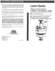
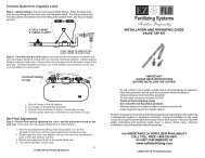
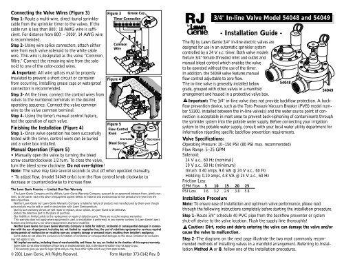
Connecting the <strong>Valve</strong> Wires (Figure 3)Step 1- Route a multi-wire, direct-burial sprinklercable from the sprinkler timer to the valves. If thecable run is less than 800', 18 AWG wire is sufficient.For distance from 800' – 2000', 14 AWG wireis recommended.Step 2- Using wire splice connectors, attach eitherwire from each valve solenoid to the white cablewire. This wire is designated as the valve “CommonWire.” Connect the remaining wire from the solenoidto one of the color-coded wires.Important: All wire splices must be properlyinsulated to prevent a short circuit or corrosionfrom occurring. Installing grease caps or waterproofconnectors is recommended.Step 3- At the timer, connect the control wires fromvalves to the numbered terminals in the desiredoperating sequence. Connect the valve commonwire to the valve common terminal.Step 4- Using the timer’s manual control feature,test the operation of each valve.Finishing the Installation (Figure 4)Step 1- Once valve operation has been successfullytested with the timer, control wires can be buriedand a valve box installed.Manual Operation (Figure 5)• Manually open the valve by turning the bleedscrew counterclockwise 1/2 turn. To close the valve,turn the bleed screw clockwise. Do not over-tighten!Figure 3 Grease CapTimer ConnectionCommonWireFigure 4Figure 5Flow ControlKnobIncreaseBleed ScrewOpenCloseNote: The valve may take several seconds to shut off when operated manually.• To adjust flow, (model 540<strong>49</strong> only) turn the flow control knob clockwise todecrease or counterclockwise to increase flow.DecreaseThe <strong>Lawn</strong> <strong>Genie</strong> Promise — Limited One-Year WarrantyThe <strong>Lawn</strong> <strong>Genie</strong> Company and its affiliate, <strong>Lawn</strong> <strong>Genie</strong> Warranty Company, pursuant to an agreement between them, jointly warrants,to the owner, each new piece of equipment against defects in material and workmanship for the period of one year from thedate of purchase.Neither <strong>Lawn</strong> <strong>Genie</strong> nor <strong>Lawn</strong> <strong>Genie</strong> Warranty Company is liable for failure of products not manufactured by them even thoughsuch products may be sold or used in conjunction with <strong>Lawn</strong> <strong>Genie</strong> products.During such warranty period, we will repair or replace, at our option, any part found to be defective.Return the defective part to the place of purchase.Our liability is limited solely to the replacement or repair of defective parts. There are no other express warranties.This warranty does not apply where equipment is used, or installation is performed, in any manner contrary to <strong>Lawn</strong> <strong>Genie</strong>’s specificationsand instructions, nor where equipment is altered or modified.Neither <strong>Lawn</strong> <strong>Genie</strong> nor <strong>Lawn</strong> <strong>Genie</strong> Warranty Company is liable for indirect, incidental or consequential damages in connectionwith the use of equipment, including but not limited to: vegetation loss, the cost of substitute equipment or services requiredduring periods of malfunction or resulting non-use, property damage or personal injury resulting from installer’s negligence.Some states do not allow the exclusion or limitation of incidental or consequential damages, so the above limitation or exclusionmay not apply to you.All implied warranties, including those of merchantability and fitness for use, are limited to the duration of this express warranty.Some states do not allow limitations of how long an implied warranty lasts, so the above limitation may not apply to you.This warranty gives you specific legal rights and you may have other rights which vary from state to state.© 2001 <strong>Lawn</strong> <strong>Genie</strong>, All Rights Reserved. Form Number 373-0142 Rev. B3/4" In-line <strong>Valve</strong> Model <strong>54048</strong> and 540<strong>49</strong>- Installation Guide -The RJ by <strong>Lawn</strong> <strong>Genie</strong> 3/4" in-line electric valves aredesigned for use in an automatic sprinkler systemcontrolled by a 24 V a.c. timer. Both valve modelsfeature 3/4" female-threaded inlet and outlet andmanual bleed control which enables the valveto be operated without the use of the timer.In addition, the 540<strong>49</strong> valve features manualflow control adjustable to zero flow.The in-line valve is generally installed belowgrade, grouped with other valves in a manifoldarrangement and housed in a protective valve box.<strong>54048</strong>Important: The 3/4" in-line valve does not provide backflow protection. A backflowprevention device, such as the Toro Pressure Vacuum Breaker (PVB) model number53300, installed between the in-line valve(s) and the water source point of connectionis acceptable in most areas to prevent back-siphoning of contaminants throughthe sprinkler system into the potable water supply. Before connecting your irrigationsystem to the potable water supply, consult with your local water utility department forinformation regarding specific backflow prevention requirements.<strong>Valve</strong> Specifications:Operating Pressure: 10–150 PSI (80 PSI max. recommended)Flow Range: 5–25 GPMSolenoid:24 V a.c., 60 Hz (nominal)19 V a.c., 60 Hz (minimum)Inrush: 0.40 amps, 9.6 VA @ 24 V a.c., 60 HzHolding: 0.20 amps, 4.8 VA @ 24 V a.c., 60 HzFriction Loss:GPM Flow 5 10 15 20 25PSI Loss 3.6 3.2 2.9 3.8 5.8540<strong>49</strong>Installation ProcedureNote: To ensure ease of installation and optimum valve performance, please readthrough the following instructions completely before starting the installation procedure.Step 1- Route 3/4" schedule 40 PVC pipe from the backflow preventer or systemshut-off device to the valve location. Flush the supply line thoroughly!Caution: Dirt, rocks and debris entering the valve can damage the valve and/orcause the valve to malfunction.Step 2- The diagrams on the next page illustrate the two most commonly recommendedmethods of installing valves in a manifold arrangement. Referring to installationMethod A or B, follow one of the installation procedures.
• Installation Method A (Figure 1)Step 1- Apply three complete wraps of Teflon ® tape to the slip/thread adapters.Caution: Use only Teflon tape on threaded connections. Pipe dope and othertypes of pipe thread sealants can damage plastic threads.Step 2- Install a slip/thread adapter into each end of the valve and tighten securely.Step 3- Cut a 4" length of 1" schedule 40 PVC pipe for each valve.Step 4- Using PVC primer and cement, assemble the valve and PVC components asshown, aligning the tee fitting perpendicular to the valve. Repeat this procedure foreach valve in the manifold.Note: The last valve in the manifold can be connected with a 90° elbow instead ofa tee. However, if future expansion of the sprinkler system is expected, use the teefitting and a 4" section of 1" schedule 40 PVC pipe capped on the end. This enablesthe main line to be easily connected to additional downstream valves.Step 5- Using 4" sections of 1" schedule 40 PVC pipe, connect the valve assembliestogether to create the manifold, making sure the valves are aligned during assembly.Step 6- Ensure the end of the supply line is dry and free of burrs. Cement themanifold to the main line.Step 7- Allow the cemented connections to cure for a minimum of one hour (orper the cement manufacturer’s directions) before applying water pressure. If noleaks occur after pressurization, begin connecting the sprinkle zone piping using1" class 200 PVC pipe.• Installation Method B (Figure 2)Step 1- Apply three complete wraps of Teflon tape to both ends of a 4" long 1" PVCthreaded pipe nipple and the slip/thread adapter.Caution: Use only Teflon tape on threaded connections. Pipe dope and othertypes of pipe thread sealants can damage plastic threads.Step 2-Install the pipe nipple to the valve inlet and tee fitting and tighten securely,aligning the tee perpendicular to the valve. Install the slip/thread adapter into thevalve outlet and tighten securely. Repeat this procedure for each valve in the manifold.Note: The last valve in the manifold can be connected with a 90° elbow instead ofa tee. However, if future expansion of the sprinkler system is expected, use the teefitting and a 4" section of 1" schedule 40 PVC pipe capped on the end. This enablesthe main line to be easily connected to additional downstream valves.Step 3- Using 4" sections of 1" schedule 40 PVC pipe, connect the valve assembliestogether to create the manifold, making sure the valves are aligned during assembly.Step 4- Ensure the end of the supply line is dry and free of burrs. Cement the manifoldto the main line.Step 5- Allow the cemented connections to cure for a minimum of one hour (orper the cement manufacturer’s directions) before applying water pressure. If noleaks occur after pressurization, begin connecting the sprinkle zone piping using1" class 200 PVC pipe.Figure 1 -Installation Method A3/4" Slip x Slip xSlip PVC Tee3/4" Slip x Slip xThread PVC Tee<strong>Valve</strong> InletFigure 2 -Installation Method B3/4" Sch 40 PVC4" Long<strong>Valve</strong> Inlet3/4" Slip x Thread Adapter(Teflon-Taped threads)<strong>Valve</strong> Manifold Assembly3/4" Sch 40 PVCWater Supply Pipe90° Elbow or Tee and Cap Plug1" Slip x Thread Adapter(Teflon-taped Threads)3/4" PVC Threaded Pipe Nipple 4" Long(Teflon-taped Threads)3/4" Schedule 40 PVC 4" Long3/4" Class 200 PVCPipe To Sprinklers