Lawn Genie Richdel L71206p-9p Controller ... - Irrigation Direct
Lawn Genie Richdel L71206p-9p Controller ... - Irrigation Direct
Lawn Genie Richdel L71206p-9p Controller ... - Irrigation Direct

Create successful ePaper yourself
Turn your PDF publications into a flip-book with our unique Google optimized e-Paper software.
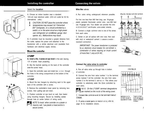
Select the location<br />
A. Choose an indoor location near a standard<br />
120-volt dual electrical outlet. (250-volt outlet far 50 Hz<br />
international<br />
!<br />
units.)<br />
CAUTION: DO NOT place the controller where<br />
temperatures may exceed 130” Fahrenheit<br />
(W Centigrade), on a circuit controlled by a<br />
switch, or on the same circuit as a high power<br />
user (refrigerator air conditioner, garage door<br />
opener. etc.). Malfunctions may result.<br />
B. If controller must be mounted a greater distance from<br />
the outlet, replace the power cord attached to the<br />
transformer with a similar electrical cord (available from<br />
hardware and electrical supply stores).<br />
Wire the valves<br />
A. Run valve wiring underground wherever possible.<br />
For line runs less than 800 feet long. use 18-gauge,<br />
plastic jacketed thermostat control wire; over 800 feet<br />
use 14-gauge wire. Your dealer can provide this wire<br />
in 2.3.4.5.6.7 and 8-wire color-coded strands.<br />
B. Connect a single common wire to one of the wires<br />
from each valve.<br />
C. Solder or join all splices with wire nuts; then seal<br />
with vinyl or waterproof cement to assure a waterresistant<br />
connection.<br />
IMPORTANT: The power transformer is protected<br />
by an electronic circuit breaker Do not connect a<br />
combination of valves requiring an inrush current<br />
of more then 1 amp at 24 VAC,<br />
6<br />
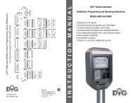
A. Install a No. 8 screw at eye level in the wall, leaving<br />
1/8" of screw head projecting.<br />
B. Slip the keyhole opening on the back of the controller<br />
over the screw head.<br />
C. Open the controller case and install two s crews through<br />
the holes in the wiring compartment at the bottom of the<br />
controller.<br />
L71209P<br />
A. Mount the two hangers by attaching each to the upper<br />
back of the controller with a screw.<br />
B. Remove the controller's lower panel by removing two<br />
screws. then pulling out and down.<br />
C. Position controller at eye level on wall, then fasten<br />
using mounting hangers. Secure by installing screw<br />
through hole at center bottom of wiring cavity<br />
NOTE nstall either controller on a plaster or<br />
PI masonry :~ wall, “use plastic or lead anchor to<br />
secure screws.<br />
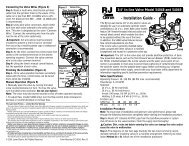
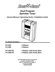
Connect the valve wires to controller<br />
A. Run all valve wires up through hole in bottom<br />
of controller.<br />
B. Connect the wire from valve number 1 to the terminal<br />
screw marked 1 on the controller: the wire from valve<br />
number 2 to the terminal 2. and so on This allows your<br />
controller to selectively water the Zone controlled by<br />
each valve,<br />
On the L71206P. terminal designations<br />
are marked on the inside of the wiring cover.<br />
page 16 for installation details.