Trus Joist Framers Handbook.pdf
Trus Joist Framers Handbook.pdf
Trus Joist Framers Handbook.pdf

Create successful ePaper yourself
Turn your PDF publications into a flip-book with our unique Google optimized e-Paper software.
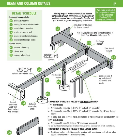
BEAM AND COLUMN DETAILS<br />
9<br />
DETAIL SCHEDULE<br />
Beam and header details<br />
L1<br />
bearing at wood wall<br />
L2<br />
bearing for door or window header<br />
L3<br />
beam to beam connection<br />
L4<br />
bearing at concrete wall<br />
L5<br />
bearing at wood or steel column<br />
L6<br />
connection of multiple pieces<br />
Column details<br />
P1 beam on column cap<br />
P2 column base<br />
P3 elevated column base<br />
Parallam ® PSL or<br />
TimberStrand ® LSL<br />
column with column cap<br />
L5<br />
Parallam ® PSL or<br />
TimberStrand ® LSL<br />
column<br />
P1<br />
Bearing length is extremely critical and must be<br />
considered for each application. See table below for<br />
minimum end and intermediate bearing lengths, and<br />
your iLevel ® TJ-Xpert ® framing plan, if applicable.<br />
L1<br />
Intermediate<br />
support<br />
P2<br />
Rim board or blocking<br />
for lateral support<br />
Cut only round holes and only in the center of<br />
beam (see Allowable Holes, page 2)<br />
Span<br />
If short span is less than 1 ⁄3 of<br />
adjacent span, additional<br />
consideration may be required<br />
L2<br />
L3<br />
This guide is intended<br />
for the products shown,<br />
and for untreated<br />
Parallam ® PSL,<br />
in dry-use conditions<br />
Top flange<br />
hanger<br />
Face mount<br />
hanger<br />
Strap per code if<br />
top plate is not<br />
continuous over<br />
header<br />
L3<br />
P3<br />
Protect<br />
untreated<br />
wood from<br />
direct contact<br />
with concrete<br />
L4<br />
Optional<br />
non-shrink<br />
grout<br />
CONNECTION OF MULTIPLE PIECES OF TOP-LOADED BEAMS (1)<br />
1 3 ⁄4" Wide Pieces<br />
■<br />
Minimum of 3 rows 10d (0.128" x 3") nails at 12" on-center<br />
■<br />
Minimum of 4 rows 10d (0.128" x 3") nails at 12" on-center for 14" and deeper<br />
beams<br />
■<br />
If using 12d–16d common nails, the number of nailing rows can be reduced by one<br />
L6<br />
3 1 ⁄2" Wide Pieces<br />
■<br />
Minimum of 2 rows 1 ⁄2" bolts at 24" on-center, staggered<br />
(1) Load must be applied evenly across entire beam width. Otherwise, use connections for side-loaded beams.<br />
CONNECTION OF MULTIPLE PIECES OF SIDE-LOADED BEAMS<br />
■<br />
Additional nailing or bolting may be required with side-loaded multiple- member<br />
beams. Refer to current product literature.