Trus Joist Framers Handbook.pdf
Trus Joist Framers Handbook.pdf
Trus Joist Framers Handbook.pdf

Create successful ePaper yourself
Turn your PDF publications into a flip-book with our unique Google optimized e-Paper software.
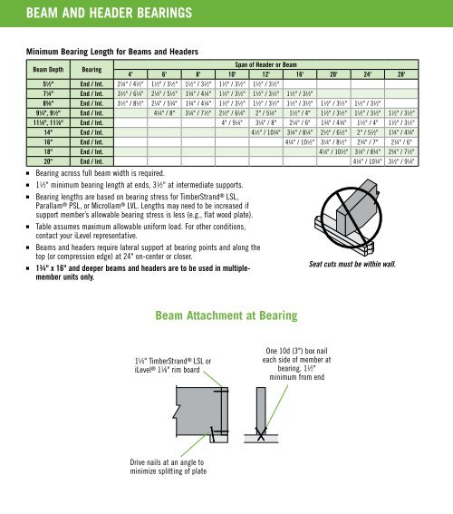
BEAM AND HEADER BEARINGS<br />
Minimum Bearing Length for Beams and Headers<br />
Beam Depth Bearing<br />
Span of Header or Beam<br />
4' 6' 8' 10' 12' 16' 20' 24' 28'<br />
5 1 ⁄2" End / Int. 2 1 ⁄4" / 4 1 ⁄2" 1 1 ⁄2" / 3 1 ⁄2" 1 1 ⁄2" / 3 1 ⁄2" 1 1 ⁄2" / 3 1 ⁄2" 1 1 ⁄2" / 3 1 ⁄2"<br />
7 1 ⁄4" End / Int. 3 1 ⁄2" / 6 1 ⁄4" 2 1 ⁄4" / 5 1 ⁄2" 1 3 ⁄4" / 4 1 ⁄4" 1 1 ⁄2" / 3 1 ⁄2" 1 1 ⁄2" / 3 1 ⁄2" 1 1 ⁄2" / 3 1 ⁄2"<br />
8 5 ⁄8" End / Int. 3 1 ⁄2" / 8 1 ⁄2" 2 1 ⁄4" / 5 3 ⁄4" 1 3 ⁄4" / 4 1 ⁄4" 1 1 ⁄2" / 3 1 ⁄2" 1 1 ⁄2" / 3 1 ⁄2" 1 1 ⁄2" / 3 1 ⁄2" 1 1 ⁄2" / 3 1 ⁄2" 1 1 ⁄2" / 3 1 ⁄2"<br />
9 1 ⁄4", 9 1 ⁄2" End / Int. 4 1 ⁄4" / 8" 3 1 ⁄4" / 7 1 ⁄2" 2 1 ⁄2" / 6 1 ⁄4" 2" / 5 1 ⁄4" 1 1 ⁄2" / 4" 1 1 ⁄2" / 3 1 ⁄2" 1 1 ⁄2" / 3 1 ⁄2" 1 1 ⁄2" / 3 1 ⁄2"<br />
11 1 ⁄4", 11 7 ⁄8" End / Int. 4" / 9 1 ⁄4" 3 1 ⁄4" / 8" 2 1 ⁄4" / 6" 1 3 ⁄4" / 4 3 ⁄4" 1 1 ⁄2" / 4" 1 1 ⁄2" / 3 1 ⁄2"<br />
14" End / Int. 4 1 ⁄2" / 10 3 ⁄4" 3 1 ⁄4" / 8 1 ⁄4" 2 1 ⁄2" / 6 1 ⁄2" 2" / 5 1 ⁄2" 1 3 ⁄4" / 4 3 ⁄4"<br />
16" End / Int. 4 1 ⁄4" / 10 1 ⁄2" 3 1 ⁄4" / 8 1 ⁄2" 2 3 ⁄4" / 7" 2 1 ⁄4" / 6"<br />
18" End / Int. 4 1 ⁄4" / 10 1 ⁄2" 3 1 ⁄4" / 8 3 ⁄4" 2 3 ⁄4" / 7 1 ⁄2"<br />
20" End / Int. 4 1 ⁄4" / 10 3 ⁄4" 3 1 ⁄2" / 9 1 ⁄4"<br />
■<br />
Bearing across full beam width is required.<br />
■<br />
1 1 ⁄2" minimum bearing length at ends, 3 1 ⁄2" at intermediate supports.<br />
■<br />
Bearing lengths are based on bearing stress for TimberStrand ® LSL,<br />
Parallam ® PSL, or Microllam ® LVL. Lengths may need to be increased if<br />
support member’s allowable bearing stress is less (e.g., flat wood plate).<br />
■<br />
Table assumes maximum allowable uniform load. For other conditions,<br />
contact your iLevel representative.<br />
■<br />
Beams and headers require lateral support at bearing points and along the<br />
top (or compression edge) at 24" on-center or closer.<br />
■<br />
1 3 ⁄4" x 16" and deeper beams and headers are to be used in multiple-<br />
Seat cuts must be within wall.<br />
member units only.<br />
Beam Attachment at Bearing<br />
1 1 ⁄4" TimberStrand ® LSL or<br />
iLevel ® 1 1 ⁄8" rim board<br />
One 10d (3") box nail<br />
each side of member at<br />
bearing, 1 1 ⁄2"<br />
minimum from end<br />
Drive nails at an angle to<br />
minimize splitting of plate