FM143 - Automatic Gate Lock - Mighty Mule
FM143 - Automatic Gate Lock - Mighty Mule
FM143 - Automatic Gate Lock - Mighty Mule

You also want an ePaper? Increase the reach of your titles
YUMPU automatically turns print PDFs into web optimized ePapers that Google loves.
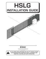
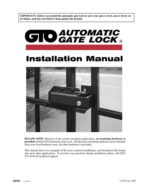
IMPORTANT: Before you install the automatic gate lock be sure your gate is level, moves freely on<br />
its hinges, and does not bind or drag against the ground.<br />
AUTOMATIC<br />
GATE LOCK ®<br />
Installation Manual<br />
PLEASE NOTE: Because of the various mounting applications, no mounting hardware is<br />
provided with the GTO <strong>Automatic</strong> <strong>Gate</strong> <strong>Lock</strong>. All necessary mounting hardware can be obtained<br />
from your local hardware store; all other hardware is provided.<br />
This manual shows two examples of the most common installations, and should provide insight<br />
into most other applications. If you have any questions during installation, please call (850)<br />
575-4144 for technical support.<br />
RB909 rev-6/23/05 © GTO, Inc. 2000<br />
13
Before You Start...<br />
For the GTO <strong>Automatic</strong> <strong>Gate</strong> <strong>Lock</strong> to work properly, the gate must close firmly and engage the lock catch against<br />
the lock receiver. Achieving optimal closure may require slight adjustments to the gate opener settings.<br />
Installing the lock with the <strong>Mighty</strong> <strong>Mule</strong> ® E-Z <strong>Gate</strong> ® Opener may require slight movement of the stroke<br />
adjustment and changes to the obstruction sensitivity. See Setting the <strong>Gate</strong> Closed Position in your <strong>Mighty</strong><br />
<strong>Mule</strong> Installation Manual for information on these adjustments.<br />
Installing the lock with a GTO/PRO gate opener may require slight movement of the stroke adjustment and<br />
changes to the obstruction sensitivity (see your GTO/PRO Installation Manual for information on these<br />
adjustments).<br />
If you are installing the lock on a Push-to-Open gate (gate opens out), the lock must be installed on the outside<br />
of the gate. Depending upon the installation, the gate post may need to be "pocketed" to accommodate the lock<br />
receiver. Contact the GTO Technical Service Department at (850) 575-4144 for assistance.<br />
Be sure you have all the parts:<br />
A - <strong>Lock</strong> with 20' of low voltage wire<br />
B - <strong>Lock</strong> Receiver<br />
C - Clevis Pin<br />
D - <strong>Lock</strong>ing Cap<br />
E - <strong>Lock</strong> Board Battery Lead Wires<br />
F - White Wire (motor lead to lock board)<br />
G - <strong>Lock</strong> Control Board<br />
H - 2 Double Spade Tongue terminals<br />
I - 6 nylon cable ties<br />
J - Wire Connector<br />
K - <strong>Lock</strong> Keys (for manual release)<br />
L - <strong>Lock</strong> Decal<br />
L<br />
I<br />
C<br />
D<br />
K<br />
AUTOMATIC<br />
GATE LOCK ®<br />
B<br />
H<br />
J<br />
E<br />
A<br />
G<br />
F<br />
What else do you need?<br />
Mounting hardware is not included. Read these instructions completely and review the installation examples to<br />
determine the mounting hardware required for your application.<br />
NOTE: The GTO <strong>Lock</strong> is designed to use mounting hardware up to 5/16" in diameter. For a more secure installation,<br />
use lock washers and lock nuts on all mounting hardware.<br />
For most IRON or ALUMINUM TUBE gates you will need:<br />
Carriage bolts, washers, and nuts for the lock and receiver. (see Illustration B, page 3)<br />
For most CHAIN LINK gates you will need:<br />
U-Bolts, saddles or carriage bolts, washers and nuts for the lock.<br />
Bolts, washers, and nuts for the receiver. (see Illustration C, page 3)<br />
The installation has two parts:<br />
(1) Mounting The <strong>Lock</strong> and <strong>Lock</strong> Receiver<br />
(2) Connecting the Control Boards<br />
Once you have the necessary mounting hardware, you can begin the installation.<br />
1
Installing The <strong>Gate</strong> <strong>Lock</strong><br />
NOTE: The <strong>Automatic</strong> <strong>Gate</strong> <strong>Lock</strong> can be installed on single and dual gate systems. Use the appropiate<br />
instructions for the system you have - SINGLE GATE (below) or DUAL GATES (page 4).<br />
Single <strong>Gate</strong> Installation<br />
Disconnect gate opener by removing hairpin clip and clevis pin from the gate bracket end of the opener.<br />
Disconnecting the opener will allow the gate to swing freely during installation of the gate lock.<br />
Step 1:<br />
Step 2:<br />
Step 3:<br />
With the gate in the closed position, determine the best location for the lock and lock receiver. The lock<br />
and receiver must be level and aligned with the opener. Also, the lock should have a solid surface or<br />
cross member to provide stability.<br />
Clamp receiver and lock together (with receiver pin hole and lock slot aligned) against the gate post,<br />
mark their positions to drill receiver holes (see Illustration B and C, page 3). The receiver must be<br />
mounted with carriage bolts, not U-bolts, to allow lock to seat properly. Fasten the receiver to the gate<br />
post.<br />
Recheck the lock's position and alignment, then mark its position for drilling holes. Drill the holes on<br />
gate supports through the slots in the lock bracket. U-bolts and saddles can be used to mount the lock<br />
on chain link gate supports. Secure the lock to the gate. Install clevis pin and locking cap by placing<br />
clevis pin through slots in lock receiver and hammering the clevis pin into the locking cap (see Illustration<br />
D), secure the lock bracket and check the alignment again.<br />
Illustration A<br />
<strong>Lock</strong> and receiver must be level<br />
and aligned with opener.<br />
Receiver pin hole and lock slot must line up.<br />
Check alignment with pin out of receiver.<br />
2
Illustration B<br />
Iron or Aluminum Tube Fence and <strong>Gate</strong> Installation<br />
Remember to check the alignment and mark positions<br />
before drilling holes in fence post and gate.<br />
Clevis Pin<br />
Receiver<br />
GTO <strong>Automatic</strong><br />
<strong>Gate</strong> <strong>Lock</strong><br />
<strong>Lock</strong>ing Cap<br />
Carriage bolts, washers, and nuts<br />
(not provided; size of<br />
fasteners depends on the gate)<br />
Illustration C<br />
Chain Link Fence and <strong>Gate</strong> Installation<br />
Remember to check the alignment and mark positions before<br />
drilling holes in fence post .<br />
Illustration D<br />
<strong>Lock</strong>ing Cap<br />
Assembly<br />
Clevis Pin<br />
Receiver<br />
Added cross member<br />
to support lock from<br />
force of slammimg shut<br />
<strong>Lock</strong><br />
<strong>Lock</strong>ing Cap<br />
U-bolts, saddles & nuts<br />
(not provided)<br />
3
Dual <strong>Gate</strong> Installation<br />
Disconnect gate openers by removing hairpin clip and clevis pin from the gate bracket end of the openers.<br />
Disconnecting the openers will allow the gates to swing freely during installation of the gate lock.<br />
NOTE: In a DUAL GATE INSTALLATION the gate opener on the same side of the driveway as the control box is<br />
known as the MASTER GATE OPENER and that gate is refered to as the MASTER GATE. Conversly the gate opener<br />
on the other gate is refered to as the SLAVE GATE OPENER and the gate is refered to as the SLAVE GATE.<br />
IMPORTANT: To use the gate lock on a dual gate system, the gate sequencing must be set so the<br />
MASTER GATE opens first and closes last, and the gate lock has to be mounted on the MASTER<br />
GATE and the lock receiver is mounted on the SLAVE GATE. If your gates are not sequenced in a<br />
manner that works like this, you'll have to change the sequencing DIP switches on your gate opener<br />
control board. Follow the instructions in your gate opener installation manual for programming dual<br />
gate sequencing.<br />
The diagrams below will show how most dual GTO/PRO® and <strong>Mighty</strong> <strong>Mule</strong>® gate sequencing is<br />
programmed. If your gate opener control board is different form these shown, please contact GTO<br />
Technical Service at 1-800-543-1236 for additional information.<br />
For <strong>Mighty</strong> <strong>Mule</strong>® FM702, GTO/PRO® 1000<br />
and GTO/PRO® 2000 Dual <strong>Gate</strong> Openers<br />
DIP switches<br />
OBSTRUCT<br />
SENS.<br />
FIRST OPERATOR OPENS FIRST,<br />
SECOND OPERATOR CLOSES FIRST<br />
SEQ1 = OFF<br />
SEQ2 = ON<br />
If SEQ1 is set to OFF, and SEQ2 is set to ON, the FIRST OPERATOR<br />
will open first, and the SECOND OPERATOR will close first.<br />
PULL/PUSH<br />
SNGL/DUAL<br />
SEQ1<br />
SEQ2<br />
ON<br />
1 2 3 4<br />
MIN<br />
LEARN<br />
MAX<br />
For <strong>Mighty</strong> <strong>Mule</strong>® FM502, GTO/PRO® 3000<br />
and GTO/PRO® 4000 Dual <strong>Gate</strong> Openers<br />
DIP switches<br />
FIRST OPERATOR OPENS FIRST,<br />
SECOND OPERATOR CLOSES FIRST<br />
Switch 1 = ON<br />
Switch 2 = OFF<br />
If Switch 1 is set to ON, and Switch 2 is set to OFF, the<br />
FIRST OPERATOR will open first, and the SECOND<br />
OPERATOR will close first.<br />
LEARN<br />
TRANSMITTER<br />
1<br />
2 3 4 5 6 7<br />
MODES<br />
ON<br />
1 2 3 4 5 6 7<br />
SET<br />
LIMIT<br />
OFF<br />
1<br />
2 3 4<br />
DUAL ON<br />
MODES<br />
ON<br />
1 2 3 4<br />
ON<br />
OFF<br />
4
With the sequencing set correctly follow the steps and diagrams below to mount the lock to the gates.<br />
Step 1:<br />
Step 2:<br />
Step 3:<br />
With the gate in the closed position, determine the best location for the lock and lock receiver. The lock<br />
and receiver must be level and aligned with the opener. Also, the lock should have a solid surface or<br />
cross member to provide stability.<br />
Clamp receiver and lock together (with receiver pin hole and lock slot aligned) to the gates, mark their<br />
positions to drill holes (see Illustration E and F, page 6). The receiver must be mounted on the SLAVE<br />
GATE with carriage bolts, not U-bolts, to allow lock to seat properly.<br />
Recheck the lock's position and alignment. Drill the holes on gate supports through the slots in the lock<br />
bracket. U-bolts and saddles can be used to mount the lock on chain link gate supports. Secure the lock<br />
to the MASTER GATE. Install clevis pin and locking cap by placing clevis pin through slots in lock<br />
receiver and hammering the clevis pin into the locking cap (see Illustration G), secure the lock bracket<br />
and check the alignment again.<br />
SLAVE GATE<br />
(second gate opener)<br />
MASTER GATE<br />
(first gate opener)<br />
<strong>Lock</strong> and receiver must be level and aligned with opener.<br />
Receiver pin hole and lock slot must line up.<br />
Check alignment with pin out of receiver.<br />
5
Illustration E<br />
Remember to check the alignment and mark positions<br />
before drilling holes in fence post and gate.<br />
Clevis Pin<br />
Receiver<br />
GTO <strong>Automatic</strong><br />
<strong>Gate</strong> <strong>Lock</strong><br />
<strong>Lock</strong>ing Cap<br />
Carriage bolts, washers, and nuts<br />
(not provided; size of<br />
fasteners depends on the gate)<br />
Illustration F<br />
Illustration G<br />
Remember to check the alignment and mark positions before<br />
drilling holes in fence post .<br />
<strong>Lock</strong>ing Cap<br />
Assembly<br />
Clevis Pin<br />
Receiver<br />
Added cross member<br />
to support lock from<br />
force of slammimg shut<br />
<strong>Lock</strong><br />
<strong>Lock</strong>ing Cap<br />
U-bolts, saddles & nuts<br />
(not provided)<br />
6
Connecting the <strong>Lock</strong> to the Opener Control Board:<br />
IMPORTANT: All <strong>Mighty</strong> <strong>Mule</strong>® and GTO/PRO® gate<br />
opener control boards manufactured since March 2000,<br />
have terminal strip wire connections (see Illustration H).<br />
If your gate opener doesn't have terminal strip connectors,<br />
you will need to follow the instructions for "Wiring<br />
the <strong>Lock</strong> to Pre-March 2000 <strong>Gate</strong> Opener Control<br />
Boards".<br />
Illustration H<br />
PLEASE NOTE:<br />
If a diagram of your control board is not pictured on page 8 or<br />
10 please call the GTO ServiceDepartment at (800) 543-1236<br />
or (850) 575-4144 for assistance.<br />
Terminal Strips<br />
Wiring the <strong>Lock</strong> to Pre-March 2000 <strong>Gate</strong> Opener Control Boards<br />
NOTE: If your gate opener control board has terminal wiring strips, skip to page 9 and follow the instructions<br />
for "Wiring the <strong>Lock</strong> to <strong>Gate</strong> Opener Control Boards with Terminal Strips".<br />
Step 1. Turn control box power switch OFF and unplug the transformer or disconnect the solar panel. Remove<br />
control box cover and disconnect battery lead wires from the battery terminals before wiring the lock<br />
board to the opener control board.<br />
Step 2. Connect the WHITE wire (included) to Terminal #1 on the lock board. Connect the RED battery lead<br />
wire (included) to Terminal #5 on the lock board. Connect the BLACK Battery lead wire (included) to<br />
Terminal #2 on the lock board. (See Wiring Chart below). DO NOT connect lock board battery lead<br />
wires to battery until Step 7!<br />
L o c k B o a r d<br />
Wiring Chart<br />
* Place a dab of petroleum<br />
jelly on the terminal contacts<br />
to prevent corrosion.<br />
<strong>Lock</strong> Board<br />
1 2 3 4 5<br />
WHITE Wire to<br />
Motor Lead<br />
BLACK Wire To Battery<br />
Negative (–) Terminal<br />
RED Wire To Battery<br />
Positive (+) Terminal<br />
RED Wire From <strong>Lock</strong><br />
BLACK Wire From <strong>Lock</strong><br />
Step 3. Attach the RED control board battery lead wire to one spade tongue on a double spade tongue connector<br />
(included). Attach the BLACK control board battery lead wire to one spade tongue on the other double<br />
spade tongue connector (included).<br />
Step 4. Attach the Wire Connector. Place the WHITE wire from the lock board inside the “blocked” channel<br />
on the Wire Connector. If the gate opens into the property (pull-to-open), place the BLACK wire from<br />
the opener power cable inside the “through” channel on the Wire Connector. Crimp the Wire Connector<br />
closed with pliers and fold plastic locking tab into place until it locks shut.<br />
7
BLACK<br />
RED<br />
BLACK<br />
BLACK<br />
RED<br />
NOTE: If the gate opens away from the property (push-to-open) place the RED wire from the opener power<br />
cable inside the “through” channel on the Wire Connector. Crimp the Wire Connector closed with pliers<br />
and fold plastic locking tab into place until it locks shut.<br />
If this is a dual gate installation, use the RED (push-to-open) or BLACK (pull-to-open) wire from the<br />
MASTER GATE OPENER that extends from the power cable to the opener.<br />
Step 5. Pull RED and BLACK wires from gate lock through the strain relief and into the control box. Attach<br />
BLACK wire to Terminal #3 on lock board. Attach RED wire to Terminal #4 on lock board (see Wiring<br />
Chart on page 7).<br />
Step 6. Attach RED lock board battery lead wire to the double spade tongue terminal with the RED control<br />
board lead wire. Attach the BLACK lock board battery lead wire to the double spade tongue connector<br />
with the BLACK control board Lead Wire.<br />
Step 7. Reconnect opener to gate bracket. Connect RED wires (with double spade tongue terminal) to<br />
POSITIVE (+) battery terminal and the BLACK wires (with double spade tongue terminal) to the<br />
NEGATIVE (–) battery terminal. Plug the transformer in and turn the control box power switch ON.<br />
Test opener and lock to make sure it functions properly and make adjustments if necessary.<br />
Double Spade<br />
Tongue Terminals<br />
12 Volt Battery<br />
Wire Connector<br />
Red Operator Lead and White <strong>Lock</strong> lead for push-to-open<br />
Black Operator Lead and White <strong>Lock</strong> lead for pull-to-open (shown)<br />
SERIES<br />
Opener<br />
Control<br />
Board<br />
(PRO)<br />
WHITE<br />
BLACK<br />
12 Volt Battery<br />
Double Spade<br />
Tongue Terminals<br />
Wire Connector<br />
Black Operator Lead and White <strong>Lock</strong> Lead for Pull-To-Open<br />
RED<br />
BLACK<br />
<strong>Lock</strong> Board<br />
Strain Relief<br />
RED & BLACK PAIR FROM LOCK<br />
Opener<br />
Control<br />
Board<br />
(Retail)<br />
BLACK<br />
WHITE<br />
BLACK<br />
AUTOMATIC GATE OPENER ®<br />
RED<br />
BLACK<br />
<strong>Lock</strong> Board<br />
Strain Relief<br />
RED & BLACK PAIR FROM LOCK<br />
8
Wiring the <strong>Lock</strong> to <strong>Gate</strong> Opener Control Boards with Terminal<br />
Strips<br />
Step 1. Turn control box power switch OFF and unplug the transformer or disconnect the solar panel. Remove<br />
control box cover and disconnect battery lead wires from the battery terminals before wiring the lock<br />
board to the opener control board.<br />
Step 2. Connect the WHITE wire (included) to Terminal #1 on the lock board. Connect the RED battery lead<br />
wire (included) to Terminal #5 on the lock board. Connect the BLACK Battery lead wire (included) to<br />
Terminal #2 on the lock board. (See <strong>Lock</strong> Board Wiring Chart below). DO NOT connect lock board battery<br />
lead wires to battery until Step 7!<br />
Step 3. Attach the RED control board battery lead wire to one spade tongue on a double spade tongue connector<br />
(included). Attach the BLACK control board battery lead wire to one spade tongue on the other double<br />
spade tongue connector (included).<br />
Step 4. Pull RED and BLACK wires from gate lock through the strain relief and into the control box. Attach<br />
BLACK wire to Terminal #3 on lock board. Attach RED wire to Terminal #4 on lock board (see <strong>Lock</strong><br />
Board Wiring Chart below).<br />
Step 5. Attach RED lock board battery lead wire to the double spade tongue terminal with the RED control<br />
board lead wire. Attach the BLACK lock board battery lead wire to the double spade tongue connector<br />
with the BLACK control board Lead Wire.<br />
Step 6. Connect the WHITE wire from the lock board directly to the MASTER OPENER terminal block along<br />
with the power cable wire from the opener arm. Connect the WHITE wire to the BLACK terminal for<br />
a Pull-to-Open installation or connect WHITE wire to the RED terminal for a Push-to-Open installation<br />
(see illustration on page 10).<br />
Step 7. Reconnect opener to gate bracket. Connect RED wires (with double spade tongue terminal) to<br />
POSITIVE (+) battery terminal and the BLACK wires (with double spade tongue terminal) to the NEG-<br />
ATIVE (–) battery terminal. Plug the transformer in or rewire the solar and turn the control box power<br />
switch ON. Test opener and lock to make sure it functions properly and make adjustments if necessary.<br />
L o c k B o a r d<br />
Wiring Chart<br />
* Place a dab of petroleum<br />
jelly on the terminal contacts<br />
to prevent corrosion.<br />
<strong>Lock</strong> Board<br />
1 2 3 4 5<br />
WHITE Wire to<br />
Motor Lead<br />
BLACK Wire To Battery<br />
Negative (–) Terminal<br />
RED Wire To Battery<br />
Positive (+) Terminal<br />
RED Wire From <strong>Lock</strong><br />
BLACK Wire From <strong>Lock</strong><br />
9
RED<br />
BLK<br />
ORG<br />
BLU<br />
GRN<br />
CLS EDG<br />
OPN EDG<br />
RED<br />
BLK<br />
ORG<br />
BLU<br />
GRN<br />
CLS EDG<br />
OPN EDG<br />
GRN<br />
ORG<br />
BLACK<br />
BLU<br />
WHT<br />
RED<br />
Wiring the <strong>Lock</strong> to <strong>Mighty</strong> <strong>Mule</strong> FM-700/702 and GTO/PRO 1000 and 2000<br />
<strong>Gate</strong> Opener Control Boards with Terminal Strips<br />
Double Spade<br />
Tongue Connectors<br />
12 Volt Battery<br />
BATT<br />
+ –<br />
PWR. SW.<br />
STATUS<br />
AUTOCLOSE<br />
OFF<br />
60<br />
INERTIA<br />
120<br />
Opener<br />
Control<br />
Board<br />
(Generation 2000)<br />
MIN MAX<br />
OBSTR.<br />
SENS.<br />
PULL/PUSH<br />
SGNL/DUAL<br />
SEQ1<br />
SEQ2<br />
MIN MAX<br />
LEARN<br />
R G B<br />
18VAC SOLAR<br />
~ ~ – +<br />
POWER IN<br />
FIRST OPERATOR<br />
SECOND OPERATOR<br />
WHITE<br />
ALARM<br />
ACCESSORY<br />
RCVR<br />
RED<br />
BLACK<br />
<strong>Lock</strong> Board<br />
Strain Relief<br />
RED & BLACK PAIR FROM LOCK<br />
15 15<br />
RED<br />
BLK<br />
GRN<br />
ORG<br />
B L U<br />
RED<br />
BLK<br />
GRN<br />
ORG<br />
B L U<br />
FIRST OPERATOR<br />
SECOND OPERATOR<br />
RED<br />
BLACK<br />
GREEN<br />
ORANGE<br />
B L<br />
U<br />
E<br />
<strong>Lock</strong> Board<br />
1 2 3 4 5<br />
Double Spade Connector<br />
Power Cable<br />
from First Operator<br />
WHITE Wire to<br />
BLACK on Operator Terminal<br />
BLACK Wire To Battery<br />
Negative (–) Terminal<br />
Double Spade Connector<br />
RED Wire To Battery<br />
Positive (+) Terminal<br />
RED Wire From <strong>Lock</strong><br />
BLACK Wire From <strong>Lock</strong><br />
10
Wiring the <strong>Lock</strong> to <strong>Mighty</strong> <strong>Mule</strong> 500/502 and GTO/PRO SW-3000 and SW-4000<br />
<strong>Gate</strong> Opener Control Boards<br />
500/502 and 3000/4000<br />
Control Board<br />
SWITCH<br />
STALL FORCE<br />
MAX<br />
MIN<br />
GRN WHT BLUE BRN ORG RED BLK COM COM<br />
MASTER INPUTS<br />
GRN<br />
WHT<br />
BLUE<br />
BRN<br />
ORG<br />
BLK<br />
CYCLE<br />
CLOSE<br />
SAFETY<br />
EXIT/<br />
OPEN<br />
SHADOW<br />
LOOP<br />
CLOSE<br />
EDGE<br />
OPEN<br />
EDGE<br />
GRN BLK RED<br />
RECEIVER<br />
RED<br />
<strong>Lock</strong> Board<br />
WHITE Wire to RED<br />
Master Terminal for<br />
Pull-To-Open gates or<br />
BLK for Push-To-Open<br />
1 2 3 4 5<br />
Double Spade Connector<br />
RED Wire To Battery<br />
Positive (+) Terminal<br />
MASTER OPENER<br />
POWER CABLE<br />
BLACK Wire To Battery<br />
Negative (–) Terminal<br />
RED Wire From <strong>Lock</strong><br />
BLACK Wire From <strong>Lock</strong><br />
Double Spade Connector<br />
Manual <strong>Lock</strong> Release:<br />
The GTO <strong>Automatic</strong> <strong>Gate</strong> <strong>Lock</strong> is keyed for manual<br />
release. Should the electronic release be disabled for any<br />
reason, simply use the key to manually open the lock.<br />
11
IMPORTANT: For the optimum service and safety, find the ideal obstruction<br />
sensing setting for your gate opener. Depending on the weight of your gate, the ideal<br />
setting will be just enough to move your gate without self-obstruction (stopping or reversing<br />
due to its own weight), yet sensitive enough to reverse and stop when it meets with<br />
an obstruction such as a car or animal. See the GTO Installation Manual for information<br />
on obstruction settings.<br />
NOTE: Be sure your gate moves freely on its hinges without binding or dragging.<br />
Limited One Year Warranty:<br />
GTO, Inc., gate opener accessories are warranted by the manufacturer against defects in workmanship for a period of one (1) year from<br />
the date of purchase, provided recommended installation procedures have been followed.<br />
In the case of product failure due to defective material or manufacturer workmanship within the one (1) year warranty period, the accessory<br />
will be repaired or replaced (at the manufacturer's option) at no charge to the customer, if returned freight prepaid to GTO, Inc.<br />
3121 Hartsfield Rd., Tallahassee, FL 32303.<br />
IMPORTANT: Call (850) 575-4144 or Fax (850) 575-8950 for a Return Goods Authorization (RGA) number before returning accessory<br />
to factory. Products received at the factory without an RGA will not be accepted. Replacement or repaired parts are covered by<br />
this warranty for the remainder of the one (1) year warranty period or six (6) months, whichever is greater. GTO, Inc. will pay the<br />
shipping costs (equivalent to United Parcel Service ground rate) for items repaired under warranty.<br />
The manufacturer will not be responsible for any charges or damages incurred in the removal of the defective parts for repair, or for the<br />
reinstallation of those parts after repair. This warranty shall be considered void if damage to the product(s) was due to improper installation<br />
or use, connection to an improper power source, or if damage was caused by lightning, wind, fire, flood, insects, or other natural<br />
agent.<br />
After the one (1) year warranty period, GTO, Inc. or one of its authorized service centers will make any necessary repairs for a nominal<br />
fee. Call GTO at (850) 575-4144 for more information. This warranty gives you specific legal rights, and you may also have other<br />
rights which may vary from state to state. This warranty is in lieu of all other warranties, expressed or implied. NOTE: Verification of<br />
the warranty period requires copies of receipts or other proof of purchase. Please retain those records.<br />
If you have any questions please call the GTO Technical Service Department:<br />
(850) 575-4144<br />
GTO, Inc. • 3121 Hartsfield Road • Tallahassee, Florida 32303 • (850) 575-0176 • Fax (850) 575-8912 • www.mightymule.com<br />
12