

SERVICE MANUAL CHANGE NOTICE
shure
shure

You also want an ePaper? Increase the reach of your titles
YUMPU automatically turns print PDFs into web optimized ePapers that Google loves.
Shure T2 Vocal Artist Microphone Transmitter<br />
2. Tack-solder the cable to side 1 of the RF circuit board as follows:<br />
<br />
<br />
Center conductor to the 50 Ω solder pad, I210<br />
Shielding to I2GN (on older versions, IGND)<br />
ETSI-Approved Units<br />
1. Obtain a 50 Ω coaxial test cable for connecting the circuit boards<br />
to various test equipment. (To construct this cable, see “50 Ω<br />
Test Cable Assembly” in the Wireless Service Equipment manual.)<br />
2. Tack-solder the cable to the bottom of the RF circuit board as follows:<br />
<br />
<br />
Center conductor to the 50 Ω solder pad, TP6<br />
Shielding to TP7 (ground)<br />
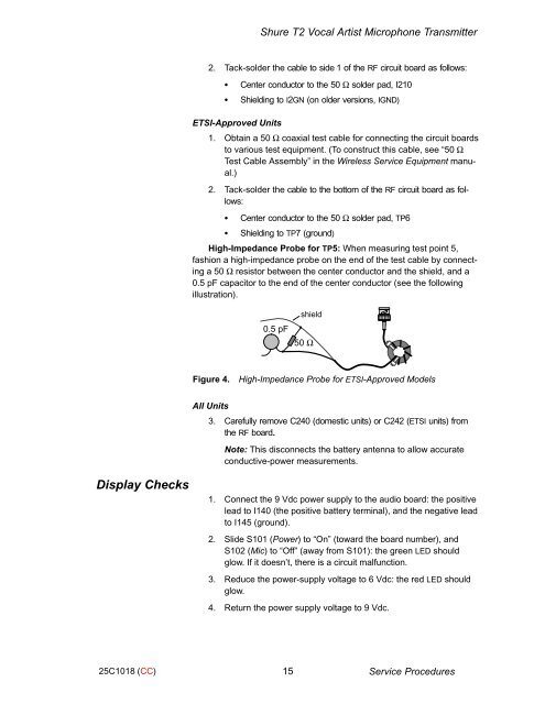
High-Impedance Probe for TP5: When measuring test point 5,<br />
fashion a high-impedance probe on the end of the test cable by connecting<br />
a 50 Ω resistor between the center conductor and the shield, and a<br />
0.5 pF capacitor to the end of the center conductor (see the following<br />
illustration).<br />
0.5 pF<br />
shield<br />
50 Ω<br />
ÌÌ<br />
Figure 4.<br />
High-Impedance Probe for ETSI-Approved Models<br />
All Units<br />
3. Carefully remove C240 (domestic units) or C242 (ETSI units) from<br />
the RF board.<br />
Note: This disconnects the battery antenna to allow accurate<br />
conductive-power measurements.<br />
Display Checks<br />
1. Connect the 9 Vdc power supply to the audio board: the positive<br />
lead to I140 (the positive battery terminal), and the negative lead<br />
to I145 (ground).<br />
2. Slide S101 (Power) to “On” (toward the board number), and<br />
S102 (Mic) to “Off” (away from S101): the green LED should<br />
glow. If it doesn’t, there is a circuit malfunction.<br />
3. Reduce the power-supply voltage to 6 Vdc: the red LED should<br />
glow.<br />
4. Return the power supply voltage to 9 Vdc.<br />
25C1018 (CC)<br />
15 Service Procedures