Table of Contents - AEP Span
Table of Contents - AEP Span
Table of Contents - AEP Span

Create successful ePaper yourself
Turn your PDF publications into a flip-book with our unique Google optimized e-Paper software.
<strong>AEP</strong> <strong>Span</strong><br />
A Division <strong>of</strong> ASC Pr<strong>of</strong>iles Inc.<br />
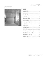
<strong>Table</strong> <strong>of</strong> <strong>Contents</strong><br />
Introduction ................................... 2<br />
Installation .................................. 2-7<br />
• Tools for Installation ...................... 2-3<br />
• Preparation Instructions...................... 3<br />
• Fastening Method .......................... 3<br />
• Sheet laying Procedures ................... 4-5<br />
• Sidelap Sealant Tape Installation .............. 5<br />
• Handling and Storage ....................... 5<br />
Notes to the Designer ......................... 6-7<br />
Klip-Rib ® Metal Ro<strong>of</strong> Details<br />
Klip-Rib Turn Up & Turn Down Tool Usage ...... 8<br />
Gutter ..................................... 9<br />
High - Low Slope Transition Flashing ...........10<br />
Low - High Slope Transition Flashing ...........11<br />
Fascia Transition............................12<br />
Hip/Ridge & Vented Ridge Flashings............13<br />
Valley & Eave Flashings ......................14<br />
Rake & Peak Flashings .......................15<br />
Sidewall Flashings ..........................16<br />
Endwall Flashings ...........................17<br />
Vent & Hot Stack Flashings ...................18<br />
Standard & Wide Curb Flashings...............19<br />
Curb (Uphill & Downhill) Flashings ............20<br />
Curb (Side) Flashings ........................21<br />
Inside and Outside Corner Flashings ............22<br />
Ro<strong>of</strong>, Fascia and S<strong>of</strong>fit at Rake.................23<br />
Mastic Placement ...........................24<br />
Drag Load Per Lineal Foot (Appendix A) ...........25<br />
Drag Load Resistance (Appendix B) ...............25<br />
Klip-Rib® Installation • October 2007
Klip Rib ® Metal Ro<strong>of</strong><br />
Installation and Flashings & Details Guide<br />
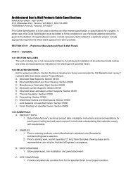
Introduction<br />
This guide is provided as an aid in the installation <strong>of</strong><br />
Klip-Rib ® . It should be used in conjunction with the<br />
notes and recommended details included in the KIip<br />
Rib ® load tables and the Contract Documents, where<br />
applicable. In addition, a 25-minute videotape which<br />
covers installation is available.<br />
Manufacturing locations:<br />
Tacoma<br />
2141 Milwaukee Way<br />
Tacoma, WA 98421<br />
253-383-4955 • 800-733-4955<br />
Fontana<br />
10905 Beech Avenue<br />
Fontana, CA 92335<br />
909-823-0401 • 800-272-2466<br />
Installation<br />
<strong>AEP</strong> <strong>Span</strong>’s’ Klip-Rib ® shall be fastened with appropriate<br />
screws to supports as per manufacturer’s recommendations<br />
(see page 6) or as called for on the<br />
Contract Documents. Steel supports should be galvanized<br />
or painted. Sheets shall have side laps facing<br />
away from the prevailing weather.<br />
Sheeting shall project a minimum <strong>of</strong> 1 1/2 inches<br />
into gutters. The maximum projection into the gutter<br />
should allow access for cleaning.<br />
When installing Klip-Rib ® over purlins and blanket<br />
insulation, the maximum insulation thickness is 4<br />
inches. The maximum recommended span between<br />
supports is 5’0”. This span should be reduced in<br />
severe wind conditions (negative load) or heavy snow<br />
loads (positive load). Contact your <strong>AEP</strong> <strong>Span</strong>’ representative<br />
with special conditions.<br />
Installation <strong>of</strong> panel sidelap sealant (see Figure<br />
1, page 5) is recommended for ro<strong>of</strong> slopes less than<br />
2:12 (minimum slope 1:12) or project conditions with<br />
potential ice damming or snow loads greater than<br />
30psf.<br />
Flashings are to be made from like finish or<br />
compatible materials as designated. High-side flashings<br />
should cover the sheets a minimum <strong>of</strong> 4 inches.<br />
Flashing attachments and caps are to be made with<br />
mechanical fasteners. Provide sealant at all trim laps<br />
and as shown in the Klip-Rib ® Flashings and Details<br />
Guide and/or the Contract Documents. Ro<strong>of</strong>s,<br />
flashings, and gutters shall be swept clean <strong>of</strong> all debris<br />
(nails, screws, cuttings, filings, etc.) at the end <strong>of</strong> each<br />
day’s work, and on completion <strong>of</strong> installation. The job<br />
shall be left clean and in a weather-tight condition. All<br />
sheating is to be installed by experienced craftsmen.<br />
Note: Designers should consult <strong>AEP</strong> <strong>Span</strong> regarding<br />
the length limitation caused by transport, and practical<br />
considerations if ro<strong>of</strong>ing panels exceed 60 feet.<br />
Special Tools For Installing Klip-Rib ®<br />
Special tools are required for the correct installation<br />
<strong>of</strong> Klip-Rib ® . The turn-up/turn-down tool is used for<br />
two purposes.<br />
The turn-up feature is used for turning up the<br />
sheet trays under the flashing at the high end <strong>of</strong> the<br />
ro<strong>of</strong>. This helps prevent any moisture from draining<br />
into the building which might accumulate under the<br />
flashing. The turn-up procedure can be done before<br />
installing the sheets or after the sheets have been fastened<br />
in place if panels are installed over purlins. In<br />
the latter case, a clearance <strong>of</strong> approximately 3 inches<br />
is required at the end <strong>of</strong> the sheets to allow room for<br />
the turn-up tool.<br />
The turn-down feature is used to turn down<br />
the pan <strong>of</strong> the<br />
panel at the<br />
low or gutter<br />
end <strong>of</strong> the ro<strong>of</strong>.<br />
This turn-down<br />
or drip edge<br />
helps prevent<br />
water from<br />
running back<br />
along the underside <strong>of</strong> the sheets and adds additional<br />
strength to the panels while eliminating “bowing” <strong>of</strong><br />
the trays. Refer to page 8 for proper use <strong>of</strong> this tool.<br />
A notching tool is used for on-site notching <strong>of</strong><br />
flashings perpendicular to the ribs. After the KIip-Rib ®<br />
sheet has been fastened and the sheet ends turned<br />
up, the flashing should be placed in correct position<br />
while notching. The lower handle <strong>of</strong> the notching<br />
tool is placed along the top <strong>of</strong> the rib with the notch-<br />
2<br />
October 2007
<strong>AEP</strong> <strong>Span</strong><br />
A Division <strong>of</strong> ASC Pr<strong>of</strong>iles Inc.<br />
ing lugs<br />
on top <strong>of</strong><br />
the rib.<br />
The top<br />
handle<br />
is then<br />
raised to<br />
its full<br />
extent and the jaw <strong>of</strong> the tool is pushed onto the flat<br />
edge <strong>of</strong> the flashing as far as it will go. Closing the<br />
handles will then notch the flashing in line with the<br />
sheet rib. This procedure is repeated on each rib for<br />
the full length <strong>of</strong> the flashing.<br />
Preparation Instructions for<br />
Klip-Rib ® Installation<br />
1. Check that the top flanges <strong>of</strong> all purlins or supports<br />
are lying in plane. Accurate alignment assures efficient<br />
locking <strong>of</strong> sheets and clips. Misalignment can interfere<br />
with the locking action, particularly where clips are<br />
closely spaced.<br />
2. To maintain maximum holding power and avoid<br />
interference when attaching the ridges, clips should<br />
be 8”-10” from the top end <strong>of</strong> the sheet and at least<br />
3” from the bottom end. The high-side trim should be<br />
fastened 8” on center.<br />
3. Make spot checks for the alignment <strong>of</strong> sheets during<br />
erection to control creeping. To rectify alignments,<br />
sheets may be adjusted 1/8” by pulling the clip away<br />
or pushing it towards the sheet while fastening the<br />
clip.<br />
4. All panels must be “fixed” with fasteners to resist<br />
drag loads. These fasteners are typically installed<br />
through the panel into the purlin or substrate under<br />
the trim at the high side <strong>of</strong> the ro<strong>of</strong>. Refer to the “Drag<br />
Load” tables found on page 25 for type and quantity<br />
<strong>of</strong> fasteners suitable for your project conditions.<br />
5. Suitable s<strong>of</strong>t-soled work shoes must be worn when<br />
walking on the ro<strong>of</strong>ing sheets. The soles must be <strong>of</strong><br />
a type that will not pick up stones and other abrasive<br />
materials that could damage the surface <strong>of</strong> the sheets.<br />
6. It is the responsibility <strong>of</strong> the installer to take proper<br />
safety precautions that are in compliance with state<br />
and local guidelines. Special attention to safety should<br />
be given to ro<strong>of</strong> perimeter areas and installation over<br />
open framing.<br />
Fastening Method<br />
Clip fasteners shall be installed in the two outbound<br />
clip holes.<br />
When four<br />
fasteners are<br />
required,<br />
the two<br />
incremental<br />
fasteners<br />
are installed<br />
in inbound<br />
holes (one each side). For attachment recommendations<br />
in severe wind environments, contact your <strong>AEP</strong><br />
<strong>Span</strong> representative. See “24 ga Fastener Guide” on<br />
page 6 for recommended fasteners.<br />
Neoprene Closures: Neoprene bottom closures<br />
should be placed during the installation <strong>of</strong> the ro<strong>of</strong><br />
panels at<br />
the bottom<br />
<strong>of</strong><br />
the slope<br />
and<br />
should<br />
be<br />
secured<br />
in place<br />
with the use <strong>of</strong> gunnable grade sealant between the<br />
flashing and the neoprene closure. Neoprene top closures<br />
should be used under flashings and on top <strong>of</strong><br />
the ro<strong>of</strong> panels to fill the void <strong>of</strong> the ro<strong>of</strong> panel trays.<br />
The top neoprene should be positioned such that the<br />
fasteners (spaced at 8” center to center) attaching the<br />
flashing to the Klip-Rib ® ribs, pass through the closure<br />
to secure it in place. Sealant should also be used<br />
between the closure, ro<strong>of</strong> panel, and flashing trim.<br />
Klip-Rib® Installation • October 2007<br />
3
Klip Rib ® Metal Ro<strong>of</strong><br />
Installation and Flashings & Details Guide<br />
Sheet Laying Procedures<br />
Step 1: When lifting Klip-Rib ® sheet lengths onto the<br />
ro<strong>of</strong> frame, make sure all sheets have the female rib<br />
facing towards the side where fastening is to begin.<br />
Attach the first run <strong>of</strong> the fastening clips using the<br />
appropriate fastening method and fasteners. Make sure<br />
that the clips are in line and located so that the sheets<br />
will be laid correctly in relation to other building elements.<br />
NOTE: Lifting <strong>of</strong> panel bundles with long panel<br />
lengths may require use <strong>of</strong> a “spreader bar” to avoid<br />
damage to ro<strong>of</strong> panels.<br />
Step 1<br />
Step 3<br />
Using the<br />
appropriate<br />
fasteners,<br />
secure the<br />
clip to the<br />
purlin or<br />
deck substrate.<br />
Should the clip position coincide with a male rib<br />
spur, deform the spur with a blow from a rubber mallet<br />
so that the clip will seat comfortably over the rib.<br />
Step 2: Lay the first sheet over the fastened run <strong>of</strong> clips<br />
by positioning the center rib first. Seat the center and<br />
female ribs onto all clips by pressing down the center<br />
Step 2<br />
rib and then the female rib over each fastening clip<br />
along the full length <strong>of</strong> the sheet. When positioning<br />
this sheet, make sure the overhang at each end is correct.<br />
Step 3: The clip has a short leg and a long leg. Position<br />
the short leg <strong>of</strong> the fastening clip over the male rib<br />
<strong>of</strong> the fastened sheet. The clip has a notch in the leg<br />
that goes over the male rib <strong>of</strong> the previous panel. The<br />
clip has to be “rocked” onto the male leg to engage<br />
the notch onto the terminating edge <strong>of</strong> the male leg.<br />
Step 4<br />
Step 4: Place the second sheet over the second run<br />
<strong>of</strong> fastening clips, again positioning the center rib first,<br />
and then push the female rib down over the male rib<br />
<strong>of</strong> the first or preceding sheet. Be sure that the ends <strong>of</strong><br />
the sheets are in line.<br />
Step 5: On shorter spans, the panel may be clipped by<br />
first walking along the center rib and then the female<br />
rib. However, a rubber mallet will be required for<br />
longer ro<strong>of</strong>ing<br />
spans<br />
and for walls.<br />
Clip both ribs<br />
over fastening<br />
clips at<br />
supports and,<br />
while walking<br />
or press-<br />
4<br />
October 2007
<strong>AEP</strong> <strong>Span</strong><br />
A Division <strong>of</strong> ASC Pr<strong>of</strong>iles Inc.<br />
ing on the panel being laid, strike its overlapping rib<br />
with short, sharp mallet blows. Repeat procedure as<br />
required between supports.<br />
Full interlocking <strong>of</strong> the ribs is essential and the free<br />
edge <strong>of</strong> the male rib must engage on the shoulder <strong>of</strong><br />
the female rib. This should be checked by standing<br />
at midspan close beside the male leg <strong>of</strong> the previously<br />
laid sheet. If it disengages, snap with the mallet.<br />
Repeat Steps 3, 4 and 5 for subsequent panels.<br />
Step 6: If the space left between the last sheet and the<br />
fascia is less than half a sheet width, it will be covered<br />
by fascia flashing. In this case, cut fastening clips in<br />
two using the short leg half, secure the male rib at<br />
each purlin. If the space left between the last sheet<br />
and the edge <strong>of</strong><br />
the ro<strong>of</strong> is more<br />
than half a panel<br />
width, the sheet to<br />
be replaced should<br />
be cut to the width<br />
required and<br />
placed as in Steps<br />
3,4 and 5.<br />
During clean-up, make sure there are no metal<br />
particles from drilling, filing, etc., remaining on the<br />
ro<strong>of</strong>. Cutting sheets with power saws on top <strong>of</strong> other<br />
sheeting should be avoided.<br />
Ro<strong>of</strong>s, flashings, and gutters should be swept<br />
clear <strong>of</strong> all debris at least at the end <strong>of</strong> each work day<br />
and upon completion <strong>of</strong> the installation. Corrosion<br />
and possible failure <strong>of</strong> the zinc/aluminum coating<br />
may occur when lead or copper-based materials are<br />
allowed to remain in contact with Zincalume ® surfaces<br />
under moist conditions.<br />
Figure 1: Sidelap Sealant Tape Installation.<br />
Gunnable<br />
Sealant Above<br />
Clip<br />
Continuous<br />
5/32"x1/4" Butyl<br />
Tape Sealant on<br />
Male Leg.<br />
Panel Clip<br />
NOTE: For severe conditions, field install<br />
gunnable butyl sealant as indicated above.<br />
Failure to take this precaution will result in unsightly<br />
staining <strong>of</strong> the Zincalume ® coating as particles oxidize<br />
during exposure.<br />
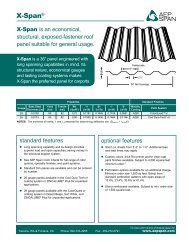
Klip-Rib ® ro<strong>of</strong>ing and siding will perform as specified<br />
if installed in accordance with the recommendations<br />
set forth in this literature.<br />
Handling and Storage<br />
Handling and storage are important to the performance<br />
<strong>of</strong> the Klip-Rib ® system. Bundles must be kept<br />
dry in transit and stored under cover, clear <strong>of</strong> the<br />
ground, to prevent water and/or condensation from<br />
being trapped between adjacent surfaces. If bundles<br />
become wet, sheets should be separated, wiped clean<br />
with a clean cloth without delay and placed so that<br />
air circulation can complete the drying process. These<br />
procedures are recommended to avoid possible deterioration<br />
<strong>of</strong> the coating which could lead to reduced<br />
life expectancy or poor appearance.<br />
Strippable Coating: Avoid exposure to direct sunlight.<br />
Remove strippable film as panels are installed.<br />
Touch-Up Painting: Application <strong>of</strong> touch-up paint<br />
to damaged paint areas that involve minor scratches<br />
is not recommended. Panels or trim that have severe<br />
paint and/or substrate damage should be replaced.<br />
Touch-up painting is not recommended due to differential<br />
fade and weathering characteristics <strong>of</strong> factory<br />
and field-applied paint systems.<br />
Klip-Rib® Installation • October 2007<br />
5
Klip Rib ® Metal Ro<strong>of</strong><br />
Installation and Flashings & Details Guide<br />
24 ga<br />
Fastener Guide<br />
* This table should be used as a<br />
guide only. Attachments for<br />
your project should be<br />
determined by an engineer.<br />
** Dekfast #14 fasteners are used<br />
for most applications with<br />
rigid insulation above deck.<br />
KL 65 modified clips must be<br />
used with Dekfast fasteners.<br />
Substate Ga u g e o r Mi n im u m Recommended<br />
Type Th i c k n es s Fastener & Qu a n t i t y<br />
per Clip<br />
Steel Supports/ 3/16”-1/2” (2) 12-24 x 1-1/2 SD<br />
Metal Decking<br />
Quadrex Drive Pancake<br />
Head, Impax #5<br />
16 ga-12 ga (2) #10-16 SD Screws<br />
18 ga (2) #10-16 SD Screws<br />
20 ga (2) #10-16 SD Screws<br />
22 ga (4) #10-16 SD Screws<br />
Rigid Insulation 18 ga (2) Dekfast #14 Screws<br />
Over Metal 20 ga (2) Dekfast #14 Screws<br />
Decking 22 ga (2) Dekfast #14 Screws<br />
Plywood 5/8” (4) #10-12 x 1” ST Screws<br />
(Group 1)<br />
(2) Dekfast #14 Screws**<br />
3/4” (4) #10-12 x 1” ST Screws<br />
(2) Dekfast #14 Screws**<br />
Hem Fir (G=.44) 1” Pene. (2) #10-12 x 1” ST Screws<br />
Doug Fir (G=.51) 1” Pene. (2) #10-12 x 1” ST Screws<br />
Notes to the Designer/User<br />
The details contained in this book are intended to<br />
be design aids. Actual conditions will vary and all situations<br />
have not been taken into account. Modifications<br />
to suit actual conditions are the responsibility <strong>of</strong> the<br />
designer/user. If product application is in high snow<br />
load conditions, please contact an <strong>AEP</strong> <strong>Span</strong> representative.<br />
Flashings: The standard style flashing has been<br />
depicted in all the details, although other details can<br />
be made to suit your aesthetic needs. Flashings which<br />
are fastened together must allow for expansion and<br />
contraction <strong>of</strong> materials and may require expansion<br />
joints where their total combined length exeeds 40 ft.<br />
See SMACNA manual for details. Heavy snow conditions<br />
require special design consideration and some<br />
details in this manual, such as valleys, may be in appro<br />
pri ate. Details shown are for applications over solid<br />
decking and are similar for applications over open<br />
framing (purlins) and rigid insulation. The dimensions<br />
shown on the flashing details in this book are suggested<br />
dimensions. They can be altered to suit specific project<br />
conditions. Certain panel and flashing details, such as<br />
panel overhangs, gutters, eaves, rakes, etc. can be easily<br />
damaged if a ladder is leaned against them. Care must<br />
be taken to avoid this. Penetrations, such as vent pipes,<br />
skylights, chimneys, etc. may require that support framing<br />
be added to maintain structural integrity and watertightness<br />
at these areas. To achieve optimum aesthetic<br />
appeal, the installer should determine a panel layout<br />
which permits the flashings running parallel to the ro<strong>of</strong>/<br />
wall panel (e.g. rake, outside corner, etc.) to be <strong>of</strong> equal<br />
size at both ends <strong>of</strong> the ro<strong>of</strong> and walls.<br />
Condensation Control: It is the designer’s responsibility<br />
to determine the need and composition <strong>of</strong> condensation<br />
control material, including insulation, vapor<br />
retarders and/or venting. Metal ro<strong>of</strong>ing is susceptible<br />
to condensation and its control should be carefully<br />
considered. An <strong>AEP</strong> <strong>Span</strong> representative is available to<br />
assist in determining the condensation control requirements<br />
<strong>of</strong> your specific project.<br />
Underlayments: Minimum requirement is 30 lb. felt<br />
or two layers <strong>of</strong> 15 lb. felt.<br />
6<br />
October 2007
<strong>AEP</strong> <strong>Span</strong><br />
A Division <strong>of</strong> ASC Pr<strong>of</strong>iles Inc.<br />
Valleys: Valley dimensions must be the proper width<br />
to account for slope, snow, ice and rain conditions.<br />
Valleys and eaves may require a special underlayment,<br />
as they are susceptible to water build-up and<br />
ice-damming. If ice or water backs up, water intrusion<br />
may occur. An underlayment such as a cold-applied<br />
membrane should be put down first, extending 4’-0” up<br />
from the center <strong>of</strong> the valley on each side and the same<br />
distance up from the eave. The 30 lb. felt should then<br />
overlap this membrane.<br />
flashing trim allowing a tab to be placed between the<br />
ribs to create a wind and weather block.<br />
Turn-up/Turn down tool: is used to “turn-up” the<br />
panel pans at the upper end <strong>of</strong> the panel, before the<br />
panels are installed to form a dam at the end <strong>of</strong> the<br />
panel which guards against water in fil tra tion due to<br />
wind-driven rain. The turn-down feature is used to “turn<br />
down” the pans at the lower end <strong>of</strong> the panel after it has<br />
been installed minimizing the problem <strong>of</strong> water wicking<br />
back un der neath the panel. See page 8 for proper use <strong>of</strong><br />
this tool.<br />
Closures: Closures on the ridge are held in place by<br />
the fasteners that attach the ridge flashing to the Klip-<br />
Rib ® panel. Closures should be caulked top and bottom<br />
with gunnable sealant if the slope 7/32” is DIA less than 3:12.<br />
(6 PL)<br />
All closures at eave and valley conditions should be<br />
caulked to the eave or valley flashing, but not to the<br />
2 1/2”<br />
panel. Expansion and con trac tion is taken out at the<br />
eave, however, the panel needs to be 9” able to slide over<br />
the closure.<br />
KL-65 CLIP<br />
Clips: There are two clips available (STANDARD for CLIP) Kip Rib.<br />
A KL-65 clip for use<br />
7/32” DIA<br />
over purlins or solid<br />
(4 PL)<br />
substrate and a KL-65<br />
modified clip for use<br />
over rigid insulation.<br />
The KL-65 modified<br />
clip has larger<br />
recessed holes to provide<br />
extra clearence<br />
for Dekfast screws.<br />
RECESSED SCREW POCKET<br />
(2 PL)<br />
KL-65 MOD. CLIP<br />
(FOR USE OVER RIGID INSULATION)<br />
7/32” DIA<br />
(6 PL)<br />
KL-65 CLIP<br />
(STANDARD CLIP)<br />
2 1/2”<br />
1 1/2”<br />
Tools: An important step in finishing <strong>of</strong>f the details<br />
7/32” DIA<br />
9/32” DIA<br />
is in the use <strong>of</strong> the two tools designed (4 PL) specifically (2 PL) for<br />
Klip-Rib ® .<br />
Notching tool: is used to notch flashing at the upper<br />
slope end <strong>of</strong> the panel. The tool pro duc es a notch in the<br />
9”<br />
9/32” DIA<br />
(2 PL)<br />
1 1/2”<br />
Application: Klip-Rib ® is secured to the substrate<br />
using concealed clips and does not act as a di a phragm.<br />
An al ter na tive bracing or diaphragm system must be<br />
employed to transfer the required shear loads. The panel<br />
must also be pinned at the ridge to resist the ‘drag’ load<br />
caused by snow loads, live loads, thermal move ment<br />
and gravity. The intensity <strong>of</strong> the drag is a function <strong>of</strong> the<br />
slope, the loads and the length <strong>of</strong> the sheet. Appendix<br />
“A” gives the drag loads for various slopes and loading<br />
conditions Appendix “B” gives lateral resistances for<br />
different materials and fastener types. Klip-Rib ® can be<br />
installed over wood, steel framing or rigid insulation.<br />
When installed directly over rigid insulation intermittent<br />
supports are not required. However, perimeter structural<br />
members are needed for pinning the panel at the ridge<br />
and for support under flashings. It is not rec om mended<br />
that Klip-Rib ® be used on slopes <strong>of</strong> less than 1:12,<br />
es pe cial ly in snow areas. Keep ro<strong>of</strong> penetrations to a<br />
minimum.<br />
All flat metal surfaces can display waviness commonly<br />
referred to as “oil canning”. This is caused by steel mill<br />
tolerances and variations in the substrate and ro<strong>of</strong>ing<br />
underlayments. Darker colors will accentuate oil canning<br />
more than lighter, more neutral colors. However,<br />
Klip Rib ® resists oil canning better than most panels due<br />
to its rib spacing and the minor ribs in the panel trays.<br />
Oil canning is an inherent characteristic <strong>of</strong> flat steel<br />
products, not a defect, and therefore is not a cause for<br />
panel rejection.<br />
Contact your <strong>AEP</strong> <strong>Span</strong> representative if you have any<br />
questions about the use or installation <strong>of</strong> Klip-Rib ® and<br />
its accessories.<br />
RECESSED SCREW POCKET<br />
(2 PL)<br />
KL-65 MOD. CLIP<br />
(FOR USE OVER RIGID INSULATION)<br />
Klip-Rib® Installation • October 2007<br />
7
Klip Rib ® Metal Ro<strong>of</strong><br />
Installation and Flashings & Details Guide<br />
Klip-Rib Turn Up & Turn Down Tool Usage<br />
8<br />
October 2007
<strong>AEP</strong> <strong>Span</strong><br />
A Division <strong>of</strong> ASC Pr<strong>of</strong>iles Inc.<br />
Gutter<br />
HOOK<br />
(VARIES)<br />
125º<br />
120º<br />
HOOK<br />
KLIP-RIB ROOF PANEL<br />
CLIP<br />
Gutter<br />
Hook<br />
120º<br />
(VARIES)<br />
Gutter<br />
HOOK<br />
(VARIES)<br />
HOOK<br />
125º<br />
120º<br />
120º<br />
(VARIES)<br />
22 GA. GALV. CONTINUOUS<br />
CLEAT FASTENED @ 12" O.C.<br />
OVER 1 ROW OF SEALANT<br />
POLYETHYLENE CLOSURE SET IN<br />
SEALANT TOP (OPTIONAL) AND BOTTOM<br />
TURN DOWN PANEL AT END<br />
1 12/" MIN. OVERHANG<br />
EAVE FLASHING, LAP 6" MIN.<br />
WITH 2 ROWS OF GUNNABLE<br />
GRADE CAULK AT LAPS<br />
PLYWOOD SHEATING<br />
22 GA. CONTINUOUS<br />
CLEAT FASTENED @ 12" O.C.<br />
OVER 1 ROW OF SEALANT<br />
KLIP-RIB ROOF PANEL<br />
CLIP<br />
22 GA. GALV. CONTINUOUS<br />
CLEAT FASTENED @ 12" O.C.<br />
OVER 1 ROW OF SEALANT<br />
POLYETHYLENE CLOSURE SET IN<br />
SEALANT TOP (OPTIONAL) AND BOTTOM<br />
TURN DOWN PANEL AT END<br />
1 12/" MIN. OVERHANG<br />
EAVE FLASHING, LAP 6" MIN.<br />
WITH 2 ROWS OF GUNNABLE<br />
GRADE CAULK AT LAPS<br />
PLYWOOD SHEATING<br />
KLIP-RIB ROOF PANEL<br />
CLIP<br />
POST HUNG GUTTER HOOK<br />
22 GA. CONTINUOUS<br />
CLEAT FASTENED @ 12" O.C.<br />
OVER 1 ROW OF SEALANT<br />
GUTTER STRAP<br />
POLYETHYLENE CLOSURE SET IN<br />
SEALANT TOP (OPTIONAL) AND BOTTOM<br />
TURN DOWN PANEL AT END<br />
1 1/2" MIN. OVERHANG<br />
POST HUNG SCULPTURED GUTTER LAP<br />
6" MIN. WITH 2 ROWS SEALANT,<br />
FASTEN LAP WITH STAINLESS<br />
STEEL BLIND RIVETS AT UPPER<br />
END OF GUTTER FACE ONLY<br />
PLYWOOD SHEATHING<br />
KLIP-RIB ROOF PANEL<br />
CLIP<br />
POST HUNG GUTTER HOOK<br />
GUTTER STRAP<br />
POLYETHYLENE CLOSURE SET IN<br />
SEALANT TOP (OPTIONAL) AND BOTTOM<br />
TURN DOWN PANEL AT END<br />
1 1/2" MIN. OVERHANG<br />
POST HUNG SCULPTURED GUTTER LAP<br />
6" MIN. WITH 2 ROWS SEALANT,<br />
FASTEN LAP WITH STAINLESS<br />
STEEL BLIND RIVETS AT UPPER<br />
Klip-Rib® Installation • October 2007<br />
END OF GUTTER FACE ONLY<br />
9
Klip Rib ® Metal Ro<strong>of</strong><br />
Installation and Flashings & Details Guide<br />
High - Low Slope Transition Flashing<br />
6"<br />
(VARIES)<br />
High-Low Slope<br />
Transition<br />
1/2" HEM<br />
KLIP-RIB ROOF PANEL<br />
CLIP<br />
8" MAX<br />
POLYETHYLENE CLOSURE SET IN<br />
SEALANT TOP (OPTIONAL) & BOTTOM<br />
SLOPE TRANSITION<br />
POLYETHYLENE CLOSURE SET IN<br />
SEALANT TOP AND BOTTOM<br />
FASTENER WITH EPDM WASHER<br />
AND COLOR MATCHED HEAD<br />
FASTEN 8" O.C. INTO RIB THROUGH CLOSURE<br />
KLIP-RIB<br />
ROOF PANEL<br />
WOOD BLOCKING<br />
UNDERLAYMENT<br />
FIELD TURN UP PAN<br />
FASTENERS TO RESIST DRAG LOAD<br />
(See appendices A&B)<br />
CLIP<br />
10<br />
October 2007
<strong>AEP</strong> <strong>Span</strong><br />
A Division <strong>of</strong> ASC Pr<strong>of</strong>iles Inc.<br />
Low - High Slope Transition Flashing<br />
(VARIES)<br />
6"<br />
Low - High Slope<br />
Transition<br />
1/2" HEM<br />
KLIP-RIB ROOF PANEL<br />
SLOPE TRANSITION<br />
CLIP<br />
8" MAX.<br />
POLYETHYLENE CLOSURE SET IN<br />
SEALANT TOP (OPTIONAL) & BOTTOM<br />
FASTENER WITH EPDM WASHER<br />
AND COLOR-MATCHED HEAD<br />
FASTEN 8" O.C. INTO RIB<br />
THROUGH CLOSURE<br />
UNDERLAYMENT<br />
WOOD BLOCKING<br />
FIELD TURN UP PAN<br />
FASTENERS TO RESIST DRAG LOAD<br />
(See appendices A&B)<br />
POLYETHYLENE CLOSURE SET IN<br />
SEALANT TOP AND BOTTOM<br />
CLIP<br />
KLIP-RIB ROOF PANEL<br />
Klip-Rib® Installation • October 2007<br />
11
Klip Rib ® Metal Ro<strong>of</strong><br />
Installation and Flashings & Details Guide<br />
Fascia Transition<br />
Drip<br />
KLIP-RIB ROOF PANEL<br />
CLIP<br />
CUT MAJOR RIBS ONLY<br />
"KNEE CAP" SEAL AND<br />
RIVET IN PLACE<br />
STRUCTURAL MEMBER<br />
KLIP-RIB FASCIA PANEL<br />
STRUCTURAL MEMBER<br />
CLIP<br />
1/4”GAP FOR DRAINAGE<br />
POLYETHYLENE CLOSURE<br />
DRIP FLASHING, LAP<br />
6" MIN. WITH 2 ROWS SEALANT<br />
Note:<br />
To eliminate flexing <strong>of</strong> the knee cap due to thermal movement<br />
<strong>of</strong> the panels, it may be desirable to make the ro<strong>of</strong><br />
and fascia separate panels where ro<strong>of</strong> panels greater than<br />
35 ft. are used.<br />
FASTENER WITH EPDM<br />
WASHER SPACED @ 24" O.C. MAX.<br />
SOFFIT PANEL<br />
12<br />
October 2007
<strong>AEP</strong> <strong>Span</strong><br />
A Division <strong>of</strong> ASC Pr<strong>of</strong>iles Inc.<br />
Hip/Ridge & Vented Ridge Flashings<br />
Hip/Ridge<br />
Hip/Ridge<br />
(optional)<br />
Vented Ridge<br />
Perforated Angle<br />
HIP/RIDGE FLASHING, FIELD<br />
NOTCH & TURN DOWN. LAP<br />
6" MIN. WITH 2 ROWS SEALANT<br />
Hip/Ridge Flashing<br />
FIELD TURN UP PAN<br />
MIN. 2 FASTENERS TO RESIST<br />
DRAG LOAD (See Appendices A&B)<br />
FASTENERS WITH EPDM WASHER<br />
AND COLOR-MATCHED HEAD<br />
FASTEN 8" O.C. INTO RIB<br />
THROUGH CLOSURE<br />
POLYETHYLENE CLOSURE SET IN<br />
SEALANT TOP & BOTTOM<br />
FIELD NOTCH & TURN DOWN TRIM<br />
* For Hips, 45º beveled closures are available<br />
KLIP-RIB ROOF PANEL<br />
UNDERLAYMENT<br />
PLYWOOD SHEATING<br />
Vented Ridge Flashing<br />
FIELD TURN UP PAN<br />
FASTENER @ 24" O.C.<br />
INTO RIB<br />
KLIP-RIB<br />
ROOF PANEL<br />
26 GA. PERFORATED ANGLE<br />
1 1/2" X 5 1/2"<br />
RIDGE FLASHING, LAP 6" MIN.<br />
WITH 2 ROWS OF SEALANT<br />
FASTENERS WITH EPDM WASHER<br />
AND COLOR-MATCHED HEAD<br />
FASTEN 8" O.C. INTO RIB<br />
UNDERLAYMENT<br />
POLYETHYLENE CLOSURE SET<br />
IN SEALANT TOP AND BOTTOM, TYP.<br />
MIN. 2 FASTENERS TO RESIST<br />
DRAG LOAD (See Appendices A&B)<br />
NOTES:<br />
• Ridge flashing dimensions larger than 8” each side may require additional support.<br />
• Free air space and dimensions to be calculated by designer.<br />
• For Hips; 45˚ beveled closures are available.<br />
Klip-Rib® Installation • October 2007<br />
13
Klip Rib ® Metal Ro<strong>of</strong><br />
Installation and Flashings & Details Guide<br />
Valley & Eave Flashings<br />
21 1/2"<br />
1"<br />
1 1/2"<br />
1 1/2"<br />
1/2"<br />
2"<br />
6"<br />
4"<br />
Valley Cleat Angle Cleat Eave<br />
Valley Flashing<br />
KLIP-RIB ROOF PANEL<br />
45º BEVELED POLYETHYLENE CLOSURE SET<br />
IN SEALANT AT BOTTOM ONLY<br />
VALLEY FLASHING, LAP<br />
12" WITH 2 ROWS SEALANT<br />
"<br />
"<br />
CLIP<br />
DETAIL A<br />
22 GA. GALV. CONT. CLEAT<br />
SEE DETAIL "A"<br />
COLD APPLIED CONT. MEMBRANE<br />
UNDERLAYMENT MIN. 48" EACH SIDE OF<br />
CENTER WITH MIN. 3" LAP IS RECOMMENDED<br />
FOR HEAVY SNOW CONDITIONS.<br />
(See "Notes To Designer")<br />
Eave Flashing<br />
"<br />
KLIP-RIB ROOF PANEL<br />
UNDERLAYMENT<br />
CLIP<br />
SEE DETAIL "A"<br />
POLYETHYLENE CLOSURE<br />
SET IN SEALANT TOP<br />
(OPTIONAL) & BOTTOM<br />
TURN DOWN PANEL<br />
1 1/2" MIN. OVERHANG<br />
22 GA. GALV. CONTINUOUS<br />
CLEAT FASTENED 12" O.C.<br />
OVER 1 ROW OF SEALANT<br />
EAVE FLASHING, LAP 6" MIN.<br />
WITH 2 ROWS OF SEALANT<br />
FASTENER WITH EPDM<br />
WASHER SPACED @ 8" O.C.<br />
POLYETHYLENE OUTSIDE CLOSURE<br />
DETAIL B<br />
SEE DETAIL "B"<br />
22 GA. GALV. CONTINUOUS<br />
CLEAT FASTENED 8" O.C.<br />
UNDERLAYMENT<br />
14<br />
NOTES:<br />
• Consult with <strong>AEP</strong> <strong>Span</strong> if heavy snow and ice conditions exist.<br />
• Minimum slope for this detail is 2:12.<br />
• 45˚ beveled closures are available.<br />
October 2007
<strong>AEP</strong> <strong>Span</strong><br />
A Division <strong>of</strong> ASC Pr<strong>of</strong>iles Inc.<br />
Rake & Peak Flashings<br />
8"<br />
8"<br />
1 3/4"<br />
6"<br />
1/2"<br />
2"<br />
6"<br />
1 3/4"<br />
Rake Angle Cleat Peak<br />
Rake Flashing<br />
KLIP-RIB ROOF PANEL<br />
UNDERLAYMENT RUN OVER ROOF<br />
EDGE OUTSIDE MAIN ENVELOPE<br />
1/2" x 1/8" BUTYL TAPE APPLIED TO THE<br />
WEATHER SIDE OF FASTENER<br />
ADD FLASHING SUPPORT AS NEEDED<br />
FASTENER WITH EPDM WASHER<br />
AND COLOR-MATCHED HEAD<br />
FASTEN 12" O.C. MAX.<br />
RAKE FLASHING, LAP 6" MIN.<br />
WITH 2 ROWS SEALANT<br />
22 GA. CONTINUOUS CLEAT<br />
FASTEN 12" O.C. WITH<br />
PANCAKE HEAD SCREW<br />
Peak Flashing<br />
PEAK FLASHING, FIELD NOTCH AND<br />
TURN DOWN. LAP FLASHINGS 6" MIN.<br />
WITH 2 ROWS OF SEALANT<br />
FIELD TURN UP PANS<br />
MIN. 2 FASTENERS TO RESIST DRAG LOAD<br />
(See Appendices A & B)<br />
FASTENER WITH EDPM WASHER AND<br />
COLOR-MATCHED HEAD FASTEN 8" O.C.<br />
INTO RIB THROUGH CLOSURE<br />
POLYETHEYLENE CLOSURE SET IN<br />
SEALANT TOP AND BOTTOM<br />
FIELD NOTCH AND TURN DOWN FLASHING<br />
KLIP-RIB ROOF PANEL<br />
UNDERLAYMENT RUN OVER ROOF<br />
EDGE OUTSIDE MAIN ENVELOPE<br />
PLYWOOD SHEATING<br />
22 GA. CONTINUOUS CLEAT<br />
FASTEN 12" O.C. WITH<br />
PANCAKE HEAD SCREW<br />
Klip-Rib® Installation • October 2007<br />
15
Klip Rib ® Metal Ro<strong>of</strong><br />
Installation and Flashings & Details Guide<br />
Sidewall Flashings<br />
HOOK<br />
1 1/2"<br />
6"<br />
HOOK<br />
1 1/2"<br />
8" MAX.<br />
HEM<br />
1 3/4"<br />
Cleat<br />
Sidewall<br />
DETAIL "A"<br />
1 ROW OF SEALANT<br />
REGLET BY OTHERS<br />
24 GA. COUNTER FLASHING<br />
FINSIHED TO MATCH PANELS<br />
APPLIED OVER SEALANT<br />
SEE DETAIL 'A'<br />
SIDEWALL FLASHING,<br />
LAP 6" MIN. WITH 2 ROWS<br />
SEALANT<br />
ADD SUPPORT IF NEEDED<br />
1/2" X 1/8" BUTYL TAPE APPLIED<br />
TO WEATHER SIDE OF THE<br />
FASTENER<br />
KLIP-RIB ROOF PANEL<br />
UNDERLAYMENT<br />
FASTENER WITH EPDM<br />
WASHER & COLOR MATCHED<br />
HEAD FASTEN 12" O.C.<br />
16<br />
October 2007
<strong>AEP</strong> <strong>Span</strong><br />
A Division <strong>of</strong> ASC Pr<strong>of</strong>iles Inc.<br />
Endwall Flashings<br />
Endwall<br />
Cleat<br />
DETAIL "A"<br />
1 ROW OF SEALANT<br />
REGLET BY OTHERS<br />
24 GA. COUNTER FLASHING<br />
FINISHED TO MATCH PANELS<br />
APPLIED OVER SEALANT<br />
22 GA. GALVANIZED CONT.<br />
CLEAT FASTEN @ 12" O.C.<br />
APPLIED OVER SEALANT<br />
SEE DETAIL "A"<br />
ENDWALL FLASHING LAP<br />
6" MIN. WITH 2 ROWS<br />
SEALANT<br />
FIELD TURN UP PANS<br />
FASTENER TO RESIST DRAG<br />
LOAD (See Appendices A & B)<br />
FASTENER WITH EPDM WASHER &<br />
COLOR-MATCHED HEAD FASTEN 8" O.C.<br />
INTO RIB AND THROUGH CLOSURE<br />
•1/2" x 1/8" BUTYL TAPE ON TOP OF<br />
RIB AT FASTENER LOCATION<br />
FIELD NOTCH & TURN DOWN FLASHING<br />
KLIP-RIB ROOF PANEL<br />
UNDERLAYMENT<br />
POLYETHYLENE CLOSURE SET IN<br />
SEALANT TOP & BOTTOM<br />
Klip-Rib® Installation • October 2007<br />
17
Klip Rib ® Metal Ro<strong>of</strong><br />
Installation and Flashings & Details Guide<br />
Vent & Hot Stack Flashings<br />
18<br />
October 2007
<strong>AEP</strong> <strong>Span</strong><br />
A Division <strong>of</strong> ASC Pr<strong>of</strong>iles Inc.<br />
Standard & Wide Curb Flashings<br />
Standard Curb Flashing<br />
Curb Flashing<br />
(Side)<br />
Curb<br />
Flashing<br />
(Uphill)<br />
CURB NOT BY <strong>AEP</strong> SPAN<br />
Curb<br />
Flashing<br />
(Downhill)<br />
See pages 19 and 20 for details.<br />
Wide Curb Flashing with Cricket<br />
Curb Flashing<br />
(Side)<br />
Curb Flashing<br />
(Side)<br />
Curb<br />
Flashing<br />
(Uphill)<br />
FOR CURBS WIDER THAN 36'<br />
A WELDED CRICKET IS REQUIRED<br />
Curb<br />
Flashing<br />
(Downhill)<br />
See pages 19 and 20 for details.<br />
Curb Flashing<br />
(Side)<br />
Klip-Rib® Installation • October 2007<br />
19
Klip Rib ® Metal Ro<strong>of</strong><br />
Installation and Flashings & Details Guide<br />
Curb (Uphill & Downhill) Flashings<br />
Curb (Uphill)<br />
Curb (Downhill)<br />
A –Curb Flashing (Uphill)<br />
B –Curb Flashing (Downhill)<br />
Note: All skylight flashings are custom<br />
due to geographical and job conditions.<br />
20<br />
October 2007
<strong>AEP</strong> <strong>Span</strong><br />
A Division <strong>of</strong> ASC Pr<strong>of</strong>iles Inc.<br />
Curb (Side) Flashings<br />
Curb (Side)<br />
Note: all skylight flashings are custom<br />
due to geographical and job conditions.<br />
C –Curb Flashing (Side)<br />
D –Curb Flashing (Side)<br />
Klip-Rib® Installation • October 2007<br />
21
Klip Rib ® Metal Ro<strong>of</strong><br />
Installation and Flashings & Details Guide<br />
Inside and Outside Corner Flashings<br />
Inside<br />
Corner<br />
Outside<br />
Corner<br />
Inside Corner Flashing<br />
KLIP-RIB WALL PANEL<br />
INSIDE CORNER FLASHING<br />
FASTENER WITH EDPM WASHER<br />
AND COLOR MATCHED HEAD<br />
FASTEN 24" O.C. MAX.<br />
See Mastic Placement Detail, Page 23<br />
Outside Corner Flashing<br />
FASTENER WITH EDPM WASHER<br />
AND COLOR MATCHED HEAD<br />
FASTEN 24" O.C. MAX.<br />
See Mastic Placement Detail, Page 23<br />
OUTSIDE CORNER FLASHING<br />
KLIP-RIB WALL PANEL<br />
22<br />
October 2007
<strong>AEP</strong> <strong>Span</strong><br />
A Division <strong>of</strong> ASC Pr<strong>of</strong>iles Inc.<br />
Ro<strong>of</strong>, Fascia and S<strong>of</strong>fit at Rake<br />
Rake Angle Cleat Drip<br />
1/2" X 1/8" BUTYL MASTIC<br />
APPLIED TO WEATHER SIDE<br />
OF FASTENER<br />
KLIP-RIB ROOF PANEL<br />
RAKE TRIM<br />
MIN. 2 FASTENERS PER PANEL<br />
(MUST BE ADEQUATE TO<br />
SUPPORT WEIGHT OF PANELS)<br />
CONTINUOUS CLEAT<br />
22 GA. GALVANIZED<br />
FASTEN @ 8" O.C.<br />
KLIP-RIB FASCIA PANEL<br />
CLIP<br />
PANCAKE HEAD SCREW<br />
@ 24" O.C.<br />
NEOPRENE INSIDE CLOSURE<br />
DRIP FLASHING<br />
SEALANT<br />
SOFFIT PANEL<br />
SOFFIT PANEL TRIM<br />
Klip-Rib® Installation • October 2007<br />
23
Klip Rib ® Metal Ro<strong>of</strong><br />
Installation and Flashings & Details Guide<br />
Mastic Placement<br />
GUNNABLE 5/32" X 1/4" SEALANT BUTYL ABOVE TAPE CLIPSEALANT<br />
GUNNABLE SEALANT UNDER CLIP<br />
KLIP-RIB ROOF ROOF PANEL PANEL<br />
CONTINUOUS 5/32” X 1/4” BUTYL TAPE SEALANT ON MALE LEG<br />
KLIP-RIB ROOF ROOF PANEL PANEL<br />
KLIP-RIB CLIP CLIP<br />
FLASHING<br />
FASTENER WITH EDPM WASHER<br />
AND COLOR-MATCHED HEAD<br />
FASTEN @ 12" O.C. MAX.<br />
1/2" X 1/8" BUTYL MASTIC<br />
APPLIED TO THE WEATHER SIDE<br />
OF FASTENER<br />
KLIP-RIB ROOF PANEL<br />
Note: Side lap sealant tape and gunnable sealant under the panel clip<br />
is required for slopes <strong>of</strong> 2:12 or less.<br />
24<br />
October 2007
<strong>AEP</strong> <strong>Span</strong><br />
A Division <strong>of</strong> ASC Pr<strong>of</strong>iles Inc.<br />
Appendices “A” and “B”<br />
Drag Load Per Lineal Foot <strong>of</strong> Klip-Rib ®<br />
Appendix A<br />
Drag Load Per Lineal Foot (PLF)<br />
Snow Load, psf<br />
Slope 25 30 35 40 45 50 55 60 65<br />
1/2:12 1.39 1.67 1.94 2.22 2.50 2.78 3.05 3.33 3.61<br />
1:12 2.77 3.32 3.88 4.43 4.98 5.54 6.09 6.64 7.20<br />
2:12 5.48 6.58 7.67 8.77 9.86 10.96 12.06 13.15 14.25<br />
3:12 8.08 9.70 11.32 12.94 14.55 16.17 17.79 19.40 21.02<br />
4:12 10.54 12.65 14.76 16.87 18.97 21.08 23.19 25.30 27.41<br />
5:12 12.82 15.38 17.95 20.51 23.08 25.64 28.21 30.77 33.33<br />
6:12 14.91 17.89 20.87 23.85 26.83 29.81 32.80 35.78 38.76<br />
7:12 16.80 20.15 23.51 26.87 30.23 33.59 36.95 40.31 43.67<br />
8:12 18.49 22.19 25.89 29.58 33.28 36.98 40.68 44.38 48.07<br />
9:12 20.00 24.00 28.00 32.00 36.00 40.00 44.00 48.00 52.00<br />
10:12 21.34 25.61 29.88 34.14 38.41 42.68 46.95 51.21 55.48<br />
11:12 22.52 27.03 31.53 36.04 40.54 45.05 49.55 54.06 58.56<br />
12:12 23.57 28.28 33.00 37.71 42.43 47.14 51.85 56.57 61.28<br />
Appendix B<br />
Klip Rib 24 gauge Drag Load Resistance<br />
Fastener Type Substrate Capacity<br />
#12-14 x 1” SD 16 ga. steel 234<br />
1/4 - 14 x 7/8” Lap SD 22 ga. steel 184<br />
#14 x 1” Type A Milled Point 1/2” plywood 128<br />
#14 x 1” Type A Milled Point 2x Douglas Fir 57<br />
Drag Load Resistance (lbs)<br />
Fastener Type<br />
Number <strong>of</strong> Fasteners per Panel<br />
2 3 4 5 6 7 8 9 10<br />
#12-14 x 1” SD 468 702 936 1170 1404 1638 1872 2106 2340<br />
#14 x 7 x 8” Lap SD 368 552 736 920 1104 1288 1472 1656 1840<br />
#14 x 1” Type A Milled Point 256 384 512 640 768 896 1024 1152 1280<br />
#14 x 1” Type A Milled Point 114 171 228 285 342 399 456 513 570<br />
Notes:<br />
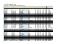
1) Multiply the sheet length by the drag load indicated in Appendix A to determine the total drag load on the<br />
sheet.<br />
2) #12-14 x 1” Impax SD values are based on a 16 gauge minimum substrate.<br />
3) 1/4-14 x 7/8“ Lap Tek values are based on a 22 gauge minimum substrate.<br />
4) #14 x 1” Type A values are based on a minimum 1/2” C-D plywood or 1” nominal Doug-Fir.<br />
5) Match the drag load figured from Appendix A with the load for the correct substrate in Appendix B to<br />
determine the number <strong>of</strong> fasteners required per panel. Place fasteners as shown in the preceding details.<br />
6) Fasteners must be located a minimum <strong>of</strong> 1” from each other and from the end <strong>of</strong> the panel.<br />
Klip-Rib® Installation • October 2007<br />
25