calculation set - PVEng
calculation set - PVEng
calculation set - PVEng

Create successful ePaper yourself
Turn your PDF publications into a flip-book with our unique Google optimized e-Paper software.
Pressure Vessel Engineering<br />
120 Randall Drive, Suite B<br />
Waterloo, Ontario, Canada<br />
N2V 1C6<br />
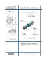
COMPRESS Pressure Vessel Design Calculations<br />
Item: Generic Vessel<br />
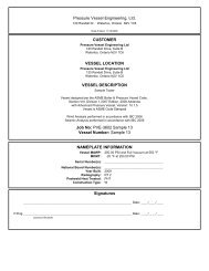
Vessel No: PVE-6847<br />
Customer: Pressure Vessel Engineering<br />
Designer: T. Briant, Brandon Twolan, Brian Munn<br />
Date: Tuesday, June 18, 2013
Table Of Contents<br />
1. Settings Summary<br />
2. Nozzle Schedule<br />
3. Nozzle Summary<br />
4. Pressure Summary<br />
5. Thickness Summary<br />
6. Weight Summary<br />
7. Hydrostatic Test<br />
8. Ellipsoidal Head, Top<br />
9. Straight Flange on Ellipsoidal Head, Top<br />
10. Shell<br />
11. Straight Flange on Ellipsoidal Head, Bottom<br />
12. Ellipsoidal Head, Bottom<br />
13. NPS 6" (N1)<br />
14. NPS 4" (N1)<br />
15. NPS 3" (N1)<br />
16. NPS 2.5 (N1)<br />
17. 2.5" CL 3000 (N2)<br />
18. 2" CL 3000 (N2)<br />
19. 1.5" CL 3000 (N2)<br />
20. 1" CL 3000 (N2)<br />
21. 2" CL 3000 (N3)<br />
22. 1.5" CL 3000 (N3)<br />
23. 1" CL 3000 (N3)<br />
24. Component Commentary<br />
25. Wind Code<br />
26. Seismic Code<br />
27. Support Skirt<br />
28. Skirt Opening 1 (SO 1)<br />
1/54
Settings Summary<br />
COMPRESS 2013 Build 7320<br />
Units: U.S. Customary<br />
Datum Line Location: 0.00" from bottom seam<br />
Design<br />
ASME Section VIII Division 1, 2010 Edition, A11 Addenda<br />
Design or Rating:<br />
Minimum thickness:<br />
Design for cold shut down only:<br />
Design for lethal service (full radiography required):<br />
Design nozzles for:<br />
Corrosion weight loss:<br />
UG-23 Stress Increase: 1.20<br />
Skirt/legs stress increase: 1.0<br />
Minimum nozzle projection: 1"<br />
Juncture <strong>calculation</strong>s for α > 30 only:<br />
Preheat P-No 1 Materials > 1.25" and
UG-22(c) Superimposed static reactions from weight of attached equipment (external loads):<br />
UG-22(d)(2) Vessel supports such as lugs, rings, skirts, saddles and legs:<br />
UG-22(f) Wind reactions:<br />
UG-22(f) Seismic reactions:<br />
UG-22(j) Test pressure and coincident static head acting during the test:<br />
Note: UG-22(b),(c) and (f) loads only considered when supports are present.<br />
No<br />
Yes<br />
Yes<br />
Yes<br />
Yes<br />
3/54
Nozzle Schedule<br />
Nozzle<br />
mark<br />
Service Size Materials<br />
Impact<br />
Tested<br />
Normalized Fine Grain Flange Blind<br />
N1 NPS 4" NPS 4 Sch 40 (Std) Nozzle SA-106 B Smls pipe No No No<br />
N1 NPS 3" NPS 3 Sch 40 (Std) Nozzle SA-106 B Smls pipe No No No<br />
N1 NPS 2.5 NPS 2.5 Sch 40 (Std) Nozzle SA-106 B Smls pipe No No No<br />
N1 NPS 6" NPS 6 Sch 40 (Std) Nozzle SA-106 B Smls pipe No No No<br />
NPS 4 Class 150<br />
SO A105<br />
NPS 3 Class 150<br />
SO A105<br />
NPS 2 1/2 Class 150<br />
SO A105<br />
NPS 6 Class 150<br />
SO A105<br />
No<br />
No<br />
No<br />
No<br />
N2 1" CL 3000 NPS 1 Class 3000 - threaded Nozzle SA-105 No No No N/A No<br />
N2 2.5" CL 3000 NPS 2.5 Class 3000 - threaded Nozzle SA-105 No No No N/A No<br />
N2 2" CL 3000 NPS 2 Class 3000 - threaded Nozzle SA-105 No No No N/A No<br />
N2 1.5" CL 3000 NPS 1.5 Class 3000 - threaded Nozzle SA-105 No No No N/A No<br />
N3 1.5" CL 3000 NPS 1.5 Class 3000 - threaded Nozzle SA-105 No No No N/A No<br />
N3 2" CL 3000 NPS 2 Class 3000 - threaded Nozzle SA-105 No No No N/A No<br />
N3 1" CL 3000 NPS 1 Class 3000 - threaded Nozzle SA-105 No No No N/A No<br />
4/54
Nozzle Summary<br />
Nozzle<br />
mark<br />
OD<br />
(in)<br />
t n<br />
(in)<br />
Req t n<br />
(in)<br />
A 1 ? A 2 ?<br />
Nom t<br />
(in)<br />
Shell<br />
Design t<br />
(in)<br />
User t<br />
(in)<br />
Reinforcement<br />
Pad<br />
Width<br />
(in)<br />
t pad<br />
(in)<br />
Corr<br />
(in)<br />
A a<br />
/A r<br />
(%)<br />
N1 4.5 0.237 0.1952 Yes Yes 0.375 0.1708 N/A N/A 0 104.7<br />
N1 3.5 0.216 0.1952 Yes Yes 0.375 0.1708 N/A N/A 0 101.4<br />
N1 2.875 0.203 0.1952 Yes Yes 0.375 0.1708 N/A N/A 0 114.4<br />
N1 6.625 0.28 0.1952 Yes Yes 0.375 0.1708 N/A N/A 0 102.4<br />
N2 1.75 0.2175 0.0938 Yes Yes 0.375 0.1708 N/A N/A 0 122.4<br />
N2 3.625 0.375 0.0938 Yes Yes 0.375 0.1708 N/A N/A 0 100.3<br />
N2 3 0.3125 0.0938 Yes Yes 0.375 0.1708 N/A N/A 0 104.3<br />
N2 2.5 0.3 0.0938 Yes Yes 0.375 0.1708 N/A N/A 0 113.1<br />
N3 2.5 0.3 0.0938 Yes Yes 0.2813* N/A N/A N/A 0 Exempt<br />
N3 3 0.3125 0.0938 Yes Yes 0.2813* N/A N/A N/A 0 Exempt<br />
N3 1.75 0.2175 0.0938 Yes Yes 0.2813* N/A N/A N/A 0 Exempt<br />
t n<br />
: Nozzle thickness<br />
Req t n<br />
: Nozzle thickness required per UG-45/UG-16<br />
Nom t: Vessel wall thickness<br />
Design t: Required vessel wall thickness due to pressure + corrosion allowance per UG-37<br />
User t: Local vessel wall thickness (near opening)<br />
A a<br />
: Area available per UG-37, governing condition<br />
A r<br />
: Area required per UG-37, governing condition<br />
Corr: Corrosion allowance on nozzle wall<br />
* Head minimum thickness after forming<br />
5/54
Pressure Summary<br />
Pressure Summary for Chamber bounded by Ellipsoidal Head, Bottom and Ellipsoidal Head, Top<br />
Identifier<br />
P<br />
Design<br />
( psi)<br />
T<br />
Design<br />
( °F)<br />
MAWP<br />
( psi)<br />
MDMT<br />
( °F)<br />
MDMT<br />
Exemption<br />
Impact<br />
Tested<br />
Ellipsoidal Head, Top 200 250 288 -20 Note 1 No<br />
Straight Flange on Ellipsoidal Head, Top 200 250 317.62 -20 Note 2 No<br />
Shell 200 250 310.85 -20 Note 3 No<br />
Straight Flange on Ellipsoidal Head, Bottom 200 250 314.08 -20 Note 2 No<br />
Ellipsoidal Head, Bottom 200 250 284.02 -20 Note 4 No<br />
NPS 6" (N1) 200 250 200 -20 Note 5 No<br />
NPS 4" (N1) 200 250 200 -20 Note 6 No<br />
NPS 3" (N1) 200 250 200 -20 Note 6 No<br />
NPS 2.5 (N1) 200 250 200 -20 Note 6 No<br />
2" CL 3000 (N2) 200 250 200 -20 Note 7 No<br />
1.5" CL 3000 (N2) 200 250 200 -20 Note 8 No<br />
1" CL 3000 (N2) 200 250 200 -20 Note 9 No<br />
2.5" CL 3000 (N2) 200 250 200 -20 Note 10 No<br />
1" CL 3000 (N3) 200 250 200 -20 Note 9 No<br />
1.5" CL 3000 (N3) 200 250 200 -20 Note 11 No<br />
2" CL 3000 (N3) 200 250 200 -20 Note 11 No<br />
Chamber design MDMT is -20 °F<br />
Chamber rated MDMT is -20 °F @ 200 psi<br />
Chamber MAWP hot & corroded is 200 psi @ 250 °F<br />
This pressure chamber is not designed for external pressure.<br />
Notes for Maximum Pressure Rating:<br />
Note #<br />
Details<br />
1.<br />
Option to calculate MAP was not selected. See the Calculation->General tab of the Set Mode<br />
dialog.<br />
6/54
Notes for MDMT Rating:<br />
Note # Exemption Details<br />
1. Straight Flange governs MDMT<br />
2. Material is impact test exempt per UG-20(f) UCS-66 governing thickness = 0.3125 in<br />
3. Material is impact test exempt per UG-20(f) UCS-66 governing thickness = 0.375 in<br />
4. Straight Flange governs MDMT<br />
5. Nozzle is impact test exempt per UG-20(f) UCS-66 governing thickness = 0.245 in.<br />
6. Flange rating governs: UCS-66(b)(1)(b)<br />
7. Nozzle is impact test exempt per UG-20(f) UCS-66 governing thickness = 0.3125 in.<br />
8. Nozzle is impact test exempt per UG-20(f) UCS-66 governing thickness = 0.3 in.<br />
9. Nozzle is impact test exempt per UG-20(f) UCS-66 governing thickness = 0.2175 in.<br />
10. Nozzle is impact test exempt per UG-20(f) UCS-66 governing thickness = 0.375 in.<br />
11. Nozzle is impact test exempt per UG-20(f) UCS-66 governing thickness = 0.2813 in.<br />
Design notes are available on the Settings Summary page.<br />
7/54
Thickness Summary<br />
Component<br />
Identifier<br />
Material<br />
Diameter<br />
(in)<br />
Length<br />
(in)<br />
Nominal t<br />
(in)<br />
Design t<br />
(in)<br />
Total Corrosion<br />
(in)<br />
Joint<br />
E<br />
Load<br />
Ellipsoidal Head, Top SA-414 G 36 OD 9.1406 0.2813* 0.1963 0 0.85 Internal<br />
Straight Flange on Ellipsoidal Head, Top SA-414 G 36 OD 2 0.3125 0.1975 0 0.85 Internal<br />
Shell SA-414 G 36 OD 96 0.375 0.2437 0 0.70 Internal<br />
Straight Flange on Ellipsoidal Head, Bottom SA-414 G 36 OD 2 0.3125 0.2009 0 0.85 Internal<br />
Ellipsoidal Head, Bottom SA-414 G 36 OD 9.1406 0.2813* 0.2001 0 0.85 Internal<br />
Support Skirt SA-36 36 ID 24 0.1875 0.0588 0 0.55 Seismic<br />
Nominal t: Vessel wall nominal thickness<br />
Design t: Required vessel thickness due to governing loading + corrosion<br />
Joint E: Longitudinal seam joint efficiency<br />
* Head minimum thickness after forming<br />
Load<br />
internal:<br />
external:<br />
Wind:<br />
Seismic:<br />
Circumferential stress due to internal pressure governs<br />
External pressure governs<br />
Combined longitudinal stress of pressure + weight + wind governs<br />
Combined longitudinal stress of pressure + weight + seismic governs<br />
8/54
Weight Summary<br />
Component<br />
Metal<br />
New*<br />
Metal<br />
Corroded* Insulation<br />
Weight ( lb) Contributed by Vessel Elements<br />
Insulation<br />
Supports Lining Piping<br />
+ Liquid<br />
Operating Liquid<br />
Test Liquid<br />
New Corroded New Corroded<br />
Ellipsoidal Head, Top 137.3 137.3 0 0 0 0 281.2 281.2 281.2 281.2 12<br />
Shell 1,130.6 1,130.6 0 0 0 0 3,387.7 3,387.7 3,387.7 3,387.7 75<br />
Ellipsoidal Head, Bottom 136.1 136.1 0 0 0 0 282.2 282.2 281.9 281.9 12<br />
Support Skirt 144.8 144.8 0 0 0 0 0 0 0 0 38<br />
TOTAL: 1,548.8 1,548.8 0 0 0 0 3,951.2 3,951.2 3,950.8 3,950.8 138<br />
* Shells with attached nozzles have weight reduced by material cut out for opening.<br />
Surface Area<br />
ft2<br />
Component<br />
Body Flanges<br />
Nozzles &<br />
Flanges<br />
New Corroded New Corroded<br />
Weight ( lb) Contributed by Attachments<br />
Packed<br />
Beds<br />
Ladders &<br />
Platforms<br />
Trays<br />
Tray<br />
Supports<br />
Rings &<br />
Clips<br />
Vertical<br />
Loads<br />
Surface Area<br />
ft2<br />
Ellipsoidal Head, Top 0 0 0 0 0 0 0 0 0 0 0<br />
Shell 0 0 61.8 61.8 0 0 0 0 0 0 2<br />
Ellipsoidal Head, Bottom 0 0 6.7 6.7 0 0 0 0 0 0 0<br />
Support Skirt 0 0 0 0 0 0 0 0 0 0 0<br />
TOTAL: 0 0 68.5 68.5 0 0 0 0 0 0 3<br />
Vessel operating weight, Corroded: 5,568 lb<br />
Vessel operating weight, New: 5,568 lb<br />
Vessel empty weight, Corroded: 1,617 lb<br />
Vessel empty weight, New: 1,617 lb<br />
Vessel test weight, New:<br />
5,568 lb<br />
Vessel test weight, Corroded: 5,568 lb<br />
Vessel surface area: 140 ft 2<br />
Vessel center of gravity location - from datum - lift condition<br />
Vessel Lift Weight, New: 1,617 lb<br />
Center of Gravity: 40.7766"<br />
Vessel Capacity<br />
Vessel Capacity** (New):<br />
473 US gal<br />
Vessel Capacity** (Corroded): 473 US gal<br />
**The vessel capacity does not include volume of nozzle, piping or other attachments.<br />
9/54
Hydrostatic Test<br />
Shop test pressure determination for Chamber bounded by Ellipsoidal Head, Bottom and Ellipsoidal Head,<br />
Top based on MAWP per UG-99(b)<br />
Shop hydrostatic test gauge pressure is 260 psi at 70 °F (the chamber MAWP = 200 psi)<br />
The shop test is performed with the vessel in the horizontal position.<br />
Identifier<br />
Local test<br />
pressure<br />
psi<br />
Test liquid<br />
static<br />
head<br />
psi<br />
UG-99(b)<br />
stress<br />
ratio<br />
UG-99(b)<br />
pressure<br />
factor<br />
Stress<br />
during<br />
test<br />
psi<br />
Allowable<br />
test stress<br />
psi<br />
Stress<br />
excessive?<br />
Ellipsoidal Head, Top (1) 261.299 1.299 1 1.30 14,813 40,500 No<br />
Straight Flange on Ellipsoidal Head, Top 261.298 1.298 1 1.30 14,920 40,500 No<br />
Shell 261.295 1.295 1 1.30 12,411 40,500 No<br />
Straight Flange on Ellipsoidal Head,<br />
Bottom<br />
261.298 1.298 1 1.30 14,920 40,500 No<br />
Ellipsoidal Head, Bottom 261.299 1.299 1 1.30 14,816 40,500 No<br />
1" CL 3000 (N2) 260.355 0.355 1 1.30 15,039 60,750 No<br />
1" CL 3000 (N3) 261.242 1.242 1 1.30 17,491 60,750 No<br />
1.5" CL 3000 (N2) 260.06 0.06 1 1.30 14,691 60,750 No<br />
1.5" CL 3000 (N3) 260.134 0.134 1 1.30 17,655 60,750 No<br />
2" CL 3000 (N2) 260.063 0.063 1 1.30 15,756 60,750 No<br />
2" CL 3000 (N3) 260.702 0.702 1 1.30 18,889 60,750 No<br />
2.5" CL 3000 (N2) 260.379 0.379 1 1.30 16,439 60,750 No<br />
NPS 2.5 (N1) 260.704 0.704 1 1.30 18,496 60,750 No<br />
NPS 3" (N1) 261.086 1.086 1 1.30 20,181 60,750 No<br />
NPS 4" (N1) 261.352 1.352 1 1.30 22,702 60,750 No<br />
NPS 6" (N1) 261.417 1.417 1 1.30 26,797 60,750 No<br />
Notes:<br />
(1) Ellipsoidal Head, Top limits the UG-99(b) stress ratio.<br />
(2) P L<br />
stresses at nozzle openings have been estimated using the method described in PVP-Vol. 399, pages 77-82.<br />
(3) 1.5*0.9*S y<br />
used as the basis for the maximum local primary membrane stress at the nozzle intersection P L<br />
.<br />
(4) The zero degree angular position is assumed to be up, and the test liquid height is assumed to the top-most<br />
flange.<br />
The field test condition has not been investigated for the Chamber bounded by Ellipsoidal Head, Bottom and<br />
Ellipsoidal Head, Top.<br />
The test temperature of 70 °F is warmer than the minimum recommended temperature of 10 °F so the brittle fracture<br />
provision of UG-99(h) has been met.<br />
10/54
Ellipsoidal Head, Top<br />
ASME Section VIII, Division 1, 2010 Edition, A11 Addenda<br />
Component:<br />
Ellipsoidal Head<br />
Material Specification: SA-414 G (II-D p.22, ln. 21)<br />
Straight Flange governs MDMT<br />
Internal design pressure: P = 200 psi @ 250 °F<br />
Static liquid head:<br />
P s<br />
= 0.32 psi (SG=1, H s<br />
=8.8594" Operating head)<br />
P th<br />
= 1.3 psi (SG=1, H s<br />
=35.979" Horizontal test head)<br />
Corrosion allowance: Inner C = 0" Outer C = 0"<br />
Design MDMT = -20°F<br />
Rated MDMT = -20°F<br />
No impact test performed<br />
Material is not normalized<br />
Material is not produced to fine grain practice<br />
PWHT is not performed<br />
Do not Optimize MDMT / Find MAWP<br />
Radiography: Category A joints - Seamless No RT<br />
Head to shell seam - None UW-11(c) Type 1<br />
Estimated weight*: new = 137.3 lb corr = 137.3 lb<br />
Capacity*: new = 33.7 US gal corr = 33.7 US gal<br />
* includes straight flange<br />
Outer diameter = 36"<br />
Minimum head thickness = 0.2813"<br />
Head ratio D/2h = 2 (new)<br />
Head ratio D/2h = 2 (corroded)<br />
Straight flange length L sf<br />
= 2"<br />
Nominal straight flange thickness t sf<br />
= 0.3125"<br />
Results Summary<br />
The governing condition is internal pressure.<br />
Minimum thickness per UG-16 = 0.0938" + 0" = 0.0938"<br />
Design thickness due to internal pressure (t) = 0.1963"<br />
Maximum allowable working pressure (MAWP) = 288 psi<br />
K (Corroded)<br />
K=(1/6)*[2 + (D / (2*h)) 2 ]=(1/6)*[2 + (35.4374 / (2*8.8594)) 2 ]=1<br />
K (New)<br />
K=(1/6)*[2 + (D / (2*h)) 2 ]=(1/6)*[2 + (35.4374 / (2*8.8594)) 2 ]=1<br />
Design thickness for internal pressure, (Corroded at 250 °F) Appendix 1-4(c)<br />
t = P*D o<br />
*K / (2*S*E + 2*P*(K - 0.1)) + Corrosion<br />
11/54
= 200.32*36*1 / (2*21,400*0.85 + 2*200.32*(1 - 0.1)) + 0<br />
= 0.1963"<br />
The head internal pressure design thickness is 0.1963".<br />
Maximum allowable working pressure, (Corroded at 250 °F) Appendix 1-4(c)<br />
P = 2*S*E*t / (K*D o<br />
- 2*t*(K - 0.1)) - P s<br />
= 2*21,400*0.85*0.2813 / (1*36 - 2*0.2813*(1 - 0.1)) - 0.32<br />
= 288 psi<br />
The maximum allowable working pressure (MAWP) is 288 psi.<br />
% Extreme fiber elongation - UCS-79(d)<br />
EFE = (75*t / R f<br />
)*(1 - R f<br />
/ R o<br />
)<br />
= (75*0.3125 / 6.1806)*(1 - 6.1806 / ∞)<br />
= 3.7921%<br />
The extreme fiber elongation does not exceed 5%.<br />
12/54
Straight Flange on Ellipsoidal Head, Top<br />
ASME Section VIII Division 1, 2010 Edition, A11 Addenda<br />
Component:<br />
Straight Flange<br />
Material specification: SA-414 G (II-D p. 22, ln. 21)<br />
Material is impact test exempt per UG-20(f)<br />
UCS-66 governing thickness = 0.3125 in<br />
Internal design pressure: P = 200 psi @ 250 °F<br />
Static liquid head:<br />
P s<br />
= 0.39 psi (SG = 1, H s<br />
= 10.8594",Operating head)<br />
(SG = 1, H<br />
P th<br />
= 1.3 psi<br />
s<br />
= 35.9478", Horizontal test<br />
head)<br />
Corrosion allowance Inner C = 0" Outer C = 0"<br />
Design MDMT = -20 °F<br />
Rated MDMT = -20 °F<br />
No impact test performed<br />
Material is not normalized<br />
Material is not produced to Fine Grain Practice<br />
PWHT is not performed<br />
Radiography: Longitudinal joint - Seamless No RT<br />
Circumferential joint - None UW-11(c) Type 1<br />
Estimated weight New = 19.8 lb<br />
corr = 19.8 lb<br />
Capacity New = 8.51 US gal corr = 8.51 US gal<br />
OD = 36"<br />
Length<br />
L c<br />
= 2"<br />
t = 0.3125"<br />
Design thickness, (at 250 °F) Appendix 1-1<br />
t = P*R o<br />
/ (S*E + 0.40*P) + Corrosion<br />
= 200.39*18 / (21,400*0.85 + 0.40*200.39) + 0<br />
= 0.1975"<br />
Maximum allowable working pressure, (at 250 °F) Appendix 1-1<br />
P = S*E*t / (R o<br />
- 0.40*t) - P s<br />
= 21,400*0.85*0.3125 / (18 - 0.40*0.3125) - 0.39<br />
= 317.62 psi<br />
% Extreme fiber elongation - UCS-79(d)<br />
EFE = (50*t / R f<br />
)*(1 - R f<br />
/ R o<br />
)<br />
= (50*0.3125 / 17.8438)*(1 - 17.8438 / ∞)<br />
= 0.8757%<br />
The extreme fiber elongation does not exceed 5%.<br />
13/54
Design thickness = 0.1975"<br />
The governing condition is due to internal pressure.<br />
The cylinder thickness of 0.3125" is adequate.<br />
Thickness Required Due to Pressure + External Loads<br />
Condition<br />
Pressure P (<br />
psi)<br />
Allowable<br />
Stress Before<br />
UG-23 Stress<br />
Increase ( psi)<br />
Temperature (<br />
°F)<br />
Corrosion C<br />
(in)<br />
Load<br />
Req'd Thk Due to<br />
Tension (in)<br />
Req'd Thk Due to<br />
Compression (in)<br />
S t<br />
S c<br />
Operating, Hot & Corroded 200 21,400 18,519 250 0<br />
Operating, Hot & New 200 21,400 18,519 250 0<br />
Hot Shut Down, Corroded 0 21,400 18,519 250 0<br />
Hot Shut Down, New 0 21,400 18,519 250 0<br />
Empty, Corroded 0 21,400 18,519 70 0<br />
Empty, New 0 21,400 18,519 70 0<br />
Wind 0.0981 0.0981<br />
Seismic 0.0984 0.0978<br />
Wind 0.0981 0.0981<br />
Seismic 0.0984 0.0978<br />
Wind 0 0.0001<br />
Seismic 0.0002 0.0003<br />
Wind 0 0.0001<br />
Seismic 0.0002 0.0003<br />
Wind 0 0.0001<br />
Seismic 0.0001 0.0002<br />
Wind 0 0.0001<br />
Seismic 0.0001 0.0002<br />
Hot Shut Down, Corroded, Weight<br />
& Eccentric Moments Only<br />
0 21,400 18,519 250 0 Weight 0.0001 0.0001<br />
14/54
Shell<br />
ASME Section VIII Division 1, 2010 Edition, A11 Addenda<br />
Component:<br />
Cylinder<br />
Material specification: SA-414 G (II-D p. 22, ln. 21)<br />
Material is impact test exempt per UG-20(f)<br />
UCS-66 governing thickness = 0.375 in<br />
Internal design pressure: P = 200 psi @ 250 °F<br />
Static liquid head:<br />
P s<br />
= 3.86 psi (SG = 1, H s<br />
= 106.8594",Operating head)<br />
(SG = 1, H<br />
P th<br />
= 1.3 psi<br />
s<br />
= 35.8853", Horizontal test<br />
head)<br />
Corrosion allowance Inner C = 0" Outer C = 0"<br />
Design MDMT = -20 °F<br />
Rated MDMT = -20 °F<br />
No impact test performed<br />
Material is not normalized<br />
Material is not produced to Fine Grain Practice<br />
PWHT is not performed<br />
Radiography: Longitudinal joint - None UW-11(c) Type 1<br />
Top circumferential joint - None UW-11(c) Type 1<br />
Bottom circumferential joint - None UW-11(c) Type 1<br />
Estimated weight New = 1,130.6 lb<br />
corr = 1,130.6 lb<br />
Capacity New = 405.57 US gal corr = 405.57 US gal<br />
OD = 36"<br />
Length<br />
L c<br />
= 96"<br />
t = 0.375"<br />
Design thickness, (at 250 °F) Appendix 1-1<br />
t = P*R o<br />
/ (S*E + 0.40*P) + Corrosion<br />
= 203.86*18 / (21,400*0.70 + 0.40*203.86) + 0<br />
= 0.2437"<br />
Maximum allowable working pressure, (at 250 °F) Appendix 1-1<br />
P = S*E*t / (R o<br />
- 0.40*t) - P s<br />
= 21,400*0.70*0.375 / (18 - 0.40*0.375) - 3.86<br />
= 310.85 psi<br />
% Extreme fiber elongation - UCS-79(d)<br />
EFE = (50*t / R f<br />
)*(1 - R f<br />
/ R o<br />
)<br />
= (50*0.375 / 17.8125)*(1 - 17.8125 / ∞)<br />
= 1.0526%<br />
The extreme fiber elongation does not exceed 5%.<br />
15/54
Design thickness = 0.2437"<br />
The governing condition is due to internal pressure.<br />
The cylinder thickness of 0.375" is adequate.<br />
Thickness Required Due to Pressure + External Loads<br />
Condition<br />
Pressure P (<br />
psi)<br />
Allowable<br />
Stress Before<br />
UG-23 Stress<br />
Increase ( psi)<br />
Temperature (<br />
°F)<br />
Corrosion C<br />
(in)<br />
Load<br />
Req'd Thk Due to<br />
Tension (in)<br />
Req'd Thk Due to<br />
Compression (in)<br />
S t<br />
S c<br />
Operating, Hot & Corroded 200 21,400 18,692 250 0<br />
Operating, Hot & New 200 21,400 18,692 250 0<br />
Hot Shut Down, Corroded 0 21,400 18,692 250 0<br />
Hot Shut Down, New 0 21,400 18,692 250 0<br />
Empty, Corroded 0 21,400 18,692 70 0<br />
Empty, New 0 21,400 18,692 70 0<br />
Wind 0.0988 0.0955<br />
Seismic 0.1267 0.0677<br />
Wind 0.0988 0.0955<br />
Seismic 0.1267 0.0677<br />
Wind 0.001 0.0019<br />
Seismic 0.0288 0.0242<br />
Wind 0.001 0.0019<br />
Seismic 0.0288 0.0242<br />
Wind 0.001 0.0019<br />
Seismic 0.0079 0.0074<br />
Wind 0.001 0.0019<br />
Seismic 0.0079 0.0074<br />
Hot Shut Down, Corroded, Weight<br />
& Eccentric Moments Only<br />
0 21,400 18,692 250 0 Weight 0.0006 0.0007<br />
16/54
Straight Flange on Ellipsoidal Head, Bottom<br />
ASME Section VIII Division 1, 2010 Edition, A11 Addenda<br />
Component:<br />
Straight Flange<br />
Material specification: SA-414 G (II-D p. 22, ln. 21)<br />
Material is impact test exempt per UG-20(f)<br />
UCS-66 governing thickness = 0.3125 in<br />
Internal design pressure: P = 200 psi @ 250 °F<br />
Static liquid head:<br />
P s<br />
= 3.93 psi (SG = 1, H s<br />
= 108.8594",Operating head)<br />
(SG = 1, H<br />
P th<br />
= 1.3 psi<br />
s<br />
= 35.9478", Horizontal test<br />
head)<br />
Corrosion allowance Inner C = 0" Outer C = 0"<br />
Design MDMT = -20 °F<br />
Rated MDMT = -20 °F<br />
No impact test performed<br />
Material is not normalized<br />
Material is not produced to Fine Grain Practice<br />
PWHT is not performed<br />
Radiography: Longitudinal joint - Seamless No RT<br />
Circumferential joint - None UW-11(c) Type 1<br />
Estimated weight New = 19.8 lb<br />
corr = 19.8 lb<br />
Capacity New = 8.51 US gal corr = 8.51 US gal<br />
OD = 36"<br />
Length<br />
L c<br />
= 2"<br />
t = 0.3125"<br />
Design thickness, (at 250 °F) Appendix 1-1<br />
t = P*R o<br />
/ (S*E + 0.40*P) + Corrosion<br />
= 203.93*18 / (21,400*0.85 + 0.40*203.93) + 0<br />
= 0.2009"<br />
Maximum allowable working pressure, (at 250 °F) Appendix 1-1<br />
P = S*E*t / (R o<br />
- 0.40*t) - P s<br />
= 21,400*0.85*0.3125 / (18 - 0.40*0.3125) - 3.93<br />
= 314.08 psi<br />
% Extreme fiber elongation - UCS-79(d)<br />
EFE = (50*t / R f<br />
)*(1 - R f<br />
/ R o<br />
)<br />
= (50*0.3125 / 17.8438)*(1 - 17.8438 / ∞)<br />
= 0.8757%<br />
The extreme fiber elongation does not exceed 5%.<br />
17/54
Design thickness = 0.2009"<br />
The governing condition is due to internal pressure.<br />
The cylinder thickness of 0.3125" is adequate.<br />
Thickness Required Due to Pressure + External Loads<br />
Condition<br />
Pressure P (<br />
psi)<br />
Allowable<br />
Stress Before<br />
UG-23 Stress<br />
Increase ( psi)<br />
Temperature (<br />
°F)<br />
Corrosion C<br />
(in)<br />
Load<br />
Req'd Thk Due to<br />
Tension (in)<br />
Req'd Thk Due to<br />
Compression (in)<br />
S t<br />
S c<br />
Operating, Hot & Corroded 200 21,400 18,519 250 0<br />
Operating, Hot & New 200 21,400 18,519 250 0<br />
Hot Shut Down, Corroded 0 21,400 18,519 250 0<br />
Hot Shut Down, New 0 21,400 18,519 250 0<br />
Empty, Corroded 0 21,400 18,519 70 0<br />
Empty, New 0 21,400 18,519 70 0<br />
Wind 0.0992 0.0958<br />
Seismic 0.1269 0.0681<br />
Wind 0.0992 0.0958<br />
Seismic 0.1269 0.0681<br />
Wind 0.001 0.0019<br />
Seismic 0.0287 0.0243<br />
Wind 0.001 0.0019<br />
Seismic 0.0287 0.0243<br />
Wind 0.001 0.0019<br />
Seismic 0.0079 0.0074<br />
Wind 0.001 0.0019<br />
Seismic 0.0079 0.0074<br />
Hot Shut Down, Corroded, Weight<br />
& Eccentric Moments Only<br />
0 21,400 18,519 250 0 Weight 0.0006 0.0007<br />
18/54
Ellipsoidal Head, Bottom<br />
ASME Section VIII, Division 1, 2010 Edition, A11 Addenda<br />
Component:<br />
Ellipsoidal Head<br />
Material Specification: SA-414 G (II-D p.22, ln. 21)<br />
Straight Flange governs MDMT<br />
Internal design pressure: P = 200 psi @ 250 °F<br />
Static liquid head:<br />
P s<br />
= 4.25 psi (SG=1, H s<br />
=117.7187" Operating head)<br />
P th<br />
= 1.3 psi (SG=1, H s<br />
=35.9791" Horizontal test head)<br />
Corrosion allowance: Inner C = 0" Outer C = 0"<br />
Design MDMT = -20°F<br />
Rated MDMT = -20°F<br />
No impact test performed<br />
Material is not normalized<br />
Material is not produced to fine grain practice<br />
PWHT is not performed<br />
Do not Optimize MDMT / Find MAWP<br />
Radiography: Category A joints - Seamless No RT<br />
Head to shell seam - None UW-11(c) Type 1<br />
Estimated weight*: new = 136.1 lb corr = 136.1 lb<br />
Capacity*: new = 33.7 US gal corr = 33.7 US gal<br />
* includes straight flange<br />
Outer diameter = 36"<br />
Minimum head thickness = 0.2813"<br />
Head ratio D/2h = 2 (new)<br />
Head ratio D/2h = 2 (corroded)<br />
Straight flange length L sf<br />
= 2"<br />
Nominal straight flange thickness t sf<br />
= 0.3125"<br />
Results Summary<br />
The governing condition is internal pressure.<br />
Minimum thickness per UG-16 = 0.0938" + 0" = 0.0938"<br />
Design thickness due to internal pressure (t) = 0.2001"<br />
Maximum allowable working pressure (MAWP) = 284.02 psi<br />
K (Corroded)<br />
K=(1/6)*[2 + (D / (2*h)) 2 ]=(1/6)*[2 + (35.4375 / (2*8.8594)) 2 ]=1<br />
K (New)<br />
K=(1/6)*[2 + (D / (2*h)) 2 ]=(1/6)*[2 + (35.4375 / (2*8.8594)) 2 ]=1<br />
Design thickness for internal pressure, (Corroded at 250 °F) Appendix 1-4(c)<br />
t = P*D o<br />
*K / (2*S*E + 2*P*(K - 0.1)) + Corrosion<br />
19/54
= 204.25*36*1 / (2*21,400*0.85 + 2*204.25*(1 - 0.1)) + 0<br />
= 0.2001"<br />
The head internal pressure design thickness is 0.2001".<br />
Maximum allowable working pressure, (Corroded at 250 °F) Appendix 1-4(c)<br />
P = 2*S*E*t / (K*D o<br />
- 2*t*(K - 0.1)) - P s<br />
= 2*21,400*0.85*0.2813 / (1*36 - 2*0.2813*(1 - 0.1)) - 4.25<br />
= 284.02 psi<br />
The maximum allowable working pressure (MAWP) is 284.02 psi.<br />
% Extreme fiber elongation - UCS-79(d)<br />
EFE = (75*t / R f<br />
)*(1 - R f<br />
/ R o<br />
)<br />
= (75*0.3125 / 6.1806)*(1 - 6.1806 / ∞)<br />
= 3.7921%<br />
The extreme fiber elongation does not exceed 5%.<br />
20/54
NPS 6" (N1)<br />
ASME Section VIII Division 1, 2010 Edition, A11 Addenda<br />
t w(lower)<br />
= 0.375 in<br />
Leg 41<br />
=<br />
0.3125 in<br />
Note: round inside edges per UG-76(c)<br />
Location and Orientation<br />
Located on:<br />
Shell<br />
Orientation: 180°<br />
Nozzle center line off<strong>set</strong> to datum line:<br />
4.875 in<br />
End of nozzle to shell center:<br />
21 in<br />
Passes through a Category A joint:<br />
No<br />
Nozzle<br />
Access opening:<br />
No<br />
Material specification: SA-106 B Smls pipe (II-D p. 10, ln. 40)<br />
Description:<br />
NPS 6 Sch 40 (Std)<br />
Inside diameter, new:<br />
6.065 in<br />
Nominal wall thickness:<br />
0.28 in<br />
Corrosion allowance:<br />
0 in<br />
Projection available outside vessel, Lpr:<br />
2.72 in<br />
Projection available outside vessel to flange face, Lf: 3 in<br />
Local vessel minimum thickness:<br />
0.375 in<br />
User input radial limit of reinforcement:<br />
4.875 in<br />
Liquid static head included:<br />
3.7908 psi<br />
Longitudinal joint efficiency: 1<br />
ASME B16.5-2009 Flange<br />
Description:<br />
NPS 6 Class 150 SO A105<br />
Bolt Material: SA-193 B7 Bolt
External fillet weld leg (UW-21):<br />
Internal fillet weld leg (UW-21):<br />
PWHT performed:<br />
Reinforcement Calculations for Internal Pressure<br />
0.392 in (0.392 in min)<br />
0.25 in (0.25 in min)<br />
No<br />
UG-37 Area Calculation Summary (in 2 )<br />
For P = 203.79 psi @ 250 °F<br />
The opening is adequately reinforced<br />
UG-45 Nozzle<br />
Wall<br />
Thickness<br />
Summary (in)<br />
The nozzle passes<br />
UG-45<br />
A<br />
required<br />
A<br />
available<br />
A 1 A 2 A 3 A 5<br />
A<br />
welds<br />
1.0549 1.0801 0.7296 0.2725 -- -- 0.078 0.1708 0.245<br />
t req<br />
t min<br />
UG-41 Weld Failure Path Analysis Summary<br />
The nozzle is exempt from weld strength <strong>calculation</strong>s<br />
per UW-15(b)(1)<br />
UW-16 Weld Sizing Summary<br />
Weld description<br />
Required weld<br />
throat size (in)<br />
Actual weld<br />
throat size (in)<br />
Status<br />
Nozzle to shell fillet (Leg 41 ) 0.196 0.2188 weld size is adequate<br />
22/54
NPS 4" (N1)<br />
ASME Section VIII Division 1, 2010 Edition, A11 Addenda<br />
t w(lower)<br />
= 0.375 in<br />
Leg 41<br />
=<br />
0.25 in<br />
Note: round inside edges per UG-76(c)<br />
Location and Orientation<br />
Located on:<br />
Shell<br />
Orientation: 150°<br />
Nozzle center line off<strong>set</strong> to datum line:<br />
3.25 in<br />
End of nozzle to shell center:<br />
21 in<br />
Passes through a Category A joint:<br />
No<br />
Nozzle<br />
Access opening:<br />
No<br />
Material specification: SA-106 B Smls pipe (II-D p. 10, ln. 40)<br />
Description:<br />
NPS 4 Sch 40 (Std)<br />
Inside diameter, new:<br />
4.026 in<br />
Nominal wall thickness:<br />
0.237 in<br />
Corrosion allowance:<br />
0 in<br />
Projection available outside vessel, Lpr:<br />
2.763 in<br />
Projection available outside vessel to flange face, Lf: 3 in<br />
Local vessel minimum thickness:<br />
0.375 in<br />
User input radial limit of reinforcement:<br />
3.25 in<br />
Liquid static head included:<br />
3.8127 psi<br />
Longitudinal joint efficiency: 1<br />
ASME B16.5-2009 Flange<br />
Description:<br />
NPS 4 Class 150 SO A105<br />
Bolt Material: SA-193 B7 Bolt
External fillet weld leg (UW-21):<br />
Internal fillet weld leg (UW-21):<br />
PWHT performed:<br />
Reinforcement Calculations for Internal Pressure<br />
0.3318 in (0.3318 in min)<br />
0.237 in (0.237 in min)<br />
No<br />
UG-37 Area Calculation Summary (in 2 )<br />
For P = 203.81 psi @ 250 °F<br />
The opening is adequately reinforced<br />
UG-45 Nozzle<br />
Wall<br />
Thickness<br />
Summary (in)<br />
The nozzle passes<br />
UG-45<br />
A<br />
required<br />
A<br />
available<br />
A 1 A 2 A 3 A 5<br />
A<br />
welds<br />
0.7038 0.7372 0.4858 0.2015 -- -- 0.0499 0.1708 0.2074<br />
t req<br />
t min<br />
UG-41 Weld Failure Path Analysis Summary<br />
The nozzle is exempt from weld strength <strong>calculation</strong>s<br />
per UW-15(b)(1)<br />
UW-16 Weld Sizing Summary<br />
Weld description<br />
Required weld<br />
throat size (in)<br />
Actual weld<br />
throat size (in)<br />
Status<br />
Nozzle to shell fillet (Leg 41 ) 0.1659 0.175 weld size is adequate<br />
24/54
NPS 3" (N1)<br />
ASME Section VIII Division 1, 2010 Edition, A11 Addenda<br />
t w(lower)<br />
= 0.375 in<br />
Leg 41<br />
=<br />
0.25 in<br />
Note: round inside edges per UG-76(c)<br />
Location and Orientation<br />
Located on:<br />
Shell<br />
Orientation: 120°<br />
Nozzle center line off<strong>set</strong> to datum line:<br />
2.375 in<br />
End of nozzle to shell center:<br />
21 in<br />
Passes through a Category A joint:<br />
No<br />
Nozzle<br />
Access opening:<br />
No<br />
Material specification: SA-106 B Smls pipe (II-D p. 10, ln. 40)<br />
Description:<br />
NPS 3 Sch 40 (Std)<br />
Inside diameter, new:<br />
3.068 in<br />
Nominal wall thickness:<br />
0.216 in<br />
Corrosion allowance:<br />
0 in<br />
Projection available outside vessel, Lpr:<br />
2.784 in<br />
Projection available outside vessel to flange face, Lf: 3 in<br />
Local vessel minimum thickness:<br />
0.375 in<br />
User input radial limit of reinforcement:<br />
2.375 in<br />
Liquid static head included:<br />
3.827 psi<br />
Longitudinal joint efficiency: 1<br />
ASME B16.5-2009 Flange<br />
Description:<br />
NPS 3 Class 150 SO A105<br />
Bolt Material: SA-193 B7 Bolt
External fillet weld leg (UW-21):<br />
Internal fillet weld leg (UW-21):<br />
PWHT performed:<br />
Reinforcement Calculations for Internal Pressure<br />
0.3024 in (0.3024 in min)<br />
0.216 in (0.216 in min)<br />
No<br />
UG-37 Area Calculation Summary (in 2 )<br />
For P = 203.83 psi @ 250 °F<br />
The opening is adequately reinforced<br />
UG-45 Nozzle<br />
Wall<br />
Thickness<br />
Summary (in)<br />
The nozzle passes<br />
UG-45<br />
A<br />
required<br />
A<br />
available<br />
A 1 A 2 A 3 A 5<br />
A<br />
welds<br />
0.5388 0.5462 0.3258 0.1705 -- -- 0.0499 0.1708 0.189<br />
t req<br />
t min<br />
UG-41 Weld Failure Path Analysis Summary<br />
The nozzle is exempt from weld strength <strong>calculation</strong>s<br />
per UW-15(b)(1)<br />
UW-16 Weld Sizing Summary<br />
Weld description<br />
Required weld<br />
throat size (in)<br />
Actual weld<br />
throat size (in)<br />
Status<br />
Nozzle to shell fillet (Leg 41 ) 0.1512 0.175 weld size is adequate<br />
26/54
NPS 2.5 (N1)<br />
ASME Section VIII Division 1, 2010 Edition, A11 Addenda<br />
t w(lower)<br />
= 0.375 in<br />
Leg 41<br />
=<br />
0.25 in<br />
Note: round inside edges per UG-76(c)<br />
Location and Orientation<br />
Located on:<br />
Shell<br />
Orientation: 90°<br />
Nozzle center line off<strong>set</strong> to datum line:<br />
2 in<br />
End of nozzle to shell center:<br />
21 in<br />
Passes through a Category A joint:<br />
No<br />
Nozzle<br />
Access opening:<br />
No<br />
Material specification: SA-106 B Smls pipe (II-D p. 10, ln. 40)<br />
Description:<br />
NPS 2.5 Sch 40 (Std)<br />
Inside diameter, new:<br />
2.469 in<br />
Nominal wall thickness:<br />
0.203 in<br />
Corrosion allowance:<br />
0 in<br />
Projection available outside vessel, Lpr:<br />
2.797 in<br />
Projection available outside vessel to flange face, Lf: 3 in<br />
Local vessel minimum thickness:<br />
0.375 in<br />
User input radial limit of reinforcement:<br />
2 in<br />
Liquid static head included:<br />
3.8297 psi<br />
Longitudinal joint efficiency: 1<br />
ASME B16.5-2009 Flange<br />
Description:<br />
NPS 2.5 Class 150 SO A105<br />
Bolt Material: SA-193 B7 Bolt
External fillet weld leg (UW-21):<br />
Internal fillet weld leg (UW-21):<br />
PWHT performed:<br />
Reinforcement Calculations for Internal Pressure<br />
0.2842 in (0.2842 in min)<br />
0.203 in (0.203 in min)<br />
No<br />
UG-37 Area Calculation Summary (in 2 )<br />
For P = 203.83 psi @ 250 °F<br />
The opening is adequately reinforced<br />
UG-45 Nozzle<br />
Wall<br />
Thickness<br />
Summary (in)<br />
The nozzle passes<br />
UG-45<br />
A<br />
required<br />
A<br />
available<br />
A 1 A 2 A 3 A 5<br />
A<br />
welds<br />
0.4356 0.4985 0.296 0.1526 -- -- 0.0499 0.1708 0.1776<br />
t req<br />
t min<br />
UG-41 Weld Failure Path Analysis Summary<br />
The nozzle is exempt from weld strength <strong>calculation</strong>s<br />
per UW-15(b)(1)<br />
UW-16 Weld Sizing Summary<br />
Weld description<br />
Required weld<br />
throat size (in)<br />
Actual weld<br />
throat size (in)<br />
Status<br />
Nozzle to shell fillet (Leg 41 ) 0.1421 0.175 weld size is adequate<br />
28/54
2.5" CL 3000 (N2)<br />
ASME Section VIII Division 1, 2010 Edition, A11 Addenda<br />
t w(lower)<br />
= 0 in<br />
Leg 41<br />
=<br />
0.25 in<br />
Note: round inside edges per UG-76(c)<br />
Location and Orientation<br />
Located on:<br />
Shell<br />
Orientation: 60°<br />
Nozzle center line off<strong>set</strong> to datum line: 2.5 in<br />
End of nozzle to shell center:<br />
19 in<br />
Passes through a Category A joint: No<br />
Nozzle<br />
Access opening:<br />
Material specification: SA-105 (II-D p. 18, ln. 5)<br />
Description:<br />
Inside diameter, new:<br />
Nominal wall thickness:<br />
Corrosion allowance:<br />
Projection available outside vessel, Lpr:<br />
Local vessel minimum thickness:<br />
User input radial limit of reinforcement:<br />
Liquid static head included:<br />
No<br />
NPS 2.5 Class 3000 - threaded<br />
2.875 in<br />
0.375 in<br />
0 in<br />
1 in<br />
0.375 in<br />
2.5 in<br />
3.819 psi<br />
Longitudinal joint efficiency: 1<br />
Reinforcement Calculations for Internal Pressure<br />
29/54
UG-37 Area Calculation Summary (in 2 )<br />
For P = 203.82 psi @ 250 °F<br />
The opening is adequately reinforced<br />
UG-45 Nozzle<br />
Wall<br />
Thickness<br />
Summary (in)<br />
The nozzle passes<br />
UG-45<br />
A<br />
required<br />
A<br />
available<br />
A 1 A 2 A 3 A 5<br />
A<br />
welds<br />
0.491 0.4923 0.4339 -- -- -- 0.0584 0.0938 0.375<br />
t req<br />
t min<br />
UG-41 Weld Failure Path Analysis Summary (lb f<br />
)<br />
All failure paths are stronger than the applicable weld loads<br />
Weld load<br />
W<br />
Weld load<br />
W 1-1<br />
Path 1-1<br />
strength<br />
Weld load<br />
W 2-2<br />
Path 2-2<br />
strength<br />
4,499.97 1,249.76 40,752.35 7,268.51 13,950.63<br />
UW-16 Weld Sizing Summary<br />
Weld description<br />
Required weld<br />
throat size (in)<br />
Actual weld<br />
throat size (in)<br />
Status<br />
Nozzle to shell fillet (Leg 41 ) 0.1708 0.175 weld size is adequate<br />
30/54
2" CL 3000 (N2)<br />
ASME Section VIII Division 1, 2010 Edition, A11 Addenda<br />
t w(lower)<br />
= 0 in<br />
Leg 41<br />
=<br />
0.3125 in<br />
Note: round inside edges per UG-76(c)<br />
Location and Orientation<br />
Located on:<br />
Shell<br />
Orientation: 20°<br />
Nozzle center line off<strong>set</strong> to datum line: 2 in<br />
End of nozzle to shell center:<br />
19 in<br />
Passes through a Category A joint: No<br />
Nozzle<br />
Access opening:<br />
Material specification: SA-105 (II-D p. 18, ln. 5)<br />
Description:<br />
Inside diameter, new:<br />
Nominal wall thickness:<br />
Corrosion allowance:<br />
Projection available outside vessel, Lpr:<br />
Local vessel minimum thickness:<br />
User input radial limit of reinforcement:<br />
Liquid static head included:<br />
No<br />
NPS 2 Class 3000 - threaded<br />
2.375 in<br />
0.3125 in<br />
0 in<br />
1 in<br />
0.375 in<br />
2 in<br />
3.828 psi<br />
Longitudinal joint efficiency: 1<br />
Reinforcement Calculations for Internal Pressure<br />
31/54
UG-37 Area Calculation Summary (in 2 )<br />
For P = 203.83 psi @ 250 °F<br />
The opening is adequately reinforced<br />
UG-45 Nozzle<br />
Wall<br />
Thickness<br />
Summary (in)<br />
The nozzle passes<br />
UG-45<br />
A<br />
required<br />
A<br />
available<br />
A 1 A 2 A 3 A 5<br />
A<br />
welds<br />
0.4056 0.4231 0.3318 -- -- -- 0.0913 0.0938 0.3125<br />
t req<br />
t min<br />
UG-41 Weld Failure Path Analysis Summary (lb f<br />
)<br />
All failure paths are stronger than the applicable weld loads<br />
Weld load<br />
W<br />
Weld load<br />
W 1-1<br />
Path 1-1<br />
strength<br />
Weld load<br />
W 2-2<br />
Path 2-2<br />
strength<br />
4,311.19 1,953.82 32,900.82 6,969.45 14,431.69<br />
UW-16 Weld Sizing Summary<br />
Weld description<br />
Required weld<br />
throat size (in)<br />
Actual weld<br />
throat size (in)<br />
Status<br />
Nozzle to shell fillet (Leg 41 ) 0.1708 0.2188 weld size is adequate<br />
32/54
1.5" CL 3000 (N2)<br />
ASME Section VIII Division 1, 2010 Edition, A11 Addenda<br />
t w(lower)<br />
= 0 in<br />
Leg 41<br />
=<br />
0.3125 in<br />
Note: round inside edges per UG-76(c)<br />
Location and Orientation<br />
Located on:<br />
Shell<br />
Orientation: 340°<br />
Nozzle center line off<strong>set</strong> to datum line: 1.625 in<br />
End of nozzle to shell center:<br />
19 in<br />
Passes through a Category A joint: No<br />
Nozzle<br />
Access opening:<br />
Material specification: SA-105 (II-D p. 18, ln. 5)<br />
Description:<br />
Inside diameter, new:<br />
Nominal wall thickness:<br />
Corrosion allowance:<br />
Projection available outside vessel, Lpr:<br />
Local vessel minimum thickness:<br />
User input radial limit of reinforcement:<br />
Liquid static head included:<br />
No<br />
NPS 1.5 Class 3000 - threaded<br />
1.9 in<br />
0.3 in<br />
0 in<br />
1 in<br />
0.375 in<br />
1.625 in<br />
3.8329 psi<br />
Longitudinal joint efficiency: 1<br />
Reinforcement Calculations for Internal Pressure<br />
33/54
UG-37 Area Calculation Summary (in 2 )<br />
For P = 203.83 psi @ 250 °F<br />
The opening is adequately reinforced<br />
UG-45<br />
Nozzle Wall<br />
Thickness<br />
Summary<br />
(in)<br />
The nozzle<br />
passes UG-45<br />
A<br />
required<br />
A<br />
available<br />
A 1 A 2 A 3 A 5<br />
A<br />
welds<br />
0.3245 0.367 0.2757 -- -- -- 0.0913 0.0938 0.3<br />
t req<br />
t min<br />
UG-41 Weld Failure Path Analysis Summary (lb f<br />
)<br />
All failure paths are stronger than the applicable weld loads<br />
Weld load<br />
W<br />
Weld load<br />
W 1-1<br />
Path 1-1<br />
strength<br />
Weld load<br />
W 2-2<br />
Path 2-2<br />
strength<br />
3,666.68 1,953.82 26,540.57 6,768.82 12,026.41<br />
UW-16 Weld Sizing Summary<br />
Weld description<br />
Required weld<br />
throat size (in)<br />
Actual weld<br />
throat size (in)<br />
Status<br />
Nozzle to shell fillet (Leg 41 ) 0.1708 0.2188 weld size is adequate<br />
34/54
1" CL 3000 (N2)<br />
ASME Section VIII Division 1, 2010 Edition, A11 Addenda<br />
t w(lower)<br />
= 0 in<br />
Leg 41<br />
=<br />
0.1875 in<br />
Note: round inside edges per UG-76(c)<br />
Location and Orientation<br />
Located on:<br />
Shell<br />
Orientation: 300°<br />
Nozzle center line off<strong>set</strong> to datum line: 1.25 in<br />
End of nozzle to shell center:<br />
19 in<br />
Passes through a Category A joint: No<br />
Nozzle<br />
Access opening:<br />
Material specification: SA-105 (II-D p. 18, ln. 5)<br />
Description:<br />
Inside diameter, new:<br />
Nominal wall thickness:<br />
Corrosion allowance:<br />
Projection available outside vessel, Lpr:<br />
Local vessel minimum thickness:<br />
User input radial limit of reinforcement:<br />
Liquid static head included:<br />
No<br />
NPS 1 Class 3000 - threaded<br />
1.315 in<br />
0.2175 in<br />
0 in<br />
1 in<br />
0.375 in<br />
1.25 in<br />
3.8359 psi<br />
Longitudinal joint efficiency: 1<br />
Reinforcement Calculations for Internal Pressure<br />
35/54
UG-37 Area Calculation Summary (in 2 )<br />
For P = 203.84 psi @ 250 °F<br />
The opening is adequately reinforced<br />
UG-45 Nozzle<br />
Wall<br />
Thickness<br />
Summary (in)<br />
The nozzle passes<br />
UG-45<br />
A<br />
required<br />
A<br />
available<br />
A 1 A 2 A 3 A 5<br />
A<br />
welds<br />
0.2246 0.2749 0.242 -- -- -- 0.0329 0.0938 0.2175<br />
t req<br />
t min<br />
UG-41 Weld Failure Path Analysis Summary (lb f<br />
)<br />
All failure paths are stronger than the applicable weld loads<br />
Weld load<br />
W<br />
Weld load<br />
W 1-1<br />
Path 1-1<br />
strength<br />
Weld load<br />
W 2-2<br />
Path 2-2<br />
strength<br />
1,528.58 704.06 12,381.15 4,194.93 5,051.09<br />
UW-16 Weld Sizing Summary<br />
Weld description<br />
Required weld<br />
throat size (in)<br />
Actual weld<br />
throat size (in)<br />
Status<br />
Nozzle to shell fillet (Leg 41 ) 0.1268 0.1312 weld size is adequate<br />
36/54
2" CL 3000 (N3)<br />
ASME Section VIII Division 1, 2010 Edition, A11 Addenda<br />
t w(lower)<br />
= 0.2813 in<br />
Leg 41<br />
= 0.3125 in<br />
Leg 43<br />
= 0 in<br />
h new<br />
= 0.5 in<br />
Note: round inside edges per UG-76(c)<br />
Location and Orientation<br />
Located on:<br />
Ellipsoidal Head, Bottom<br />
Orientation: 270°<br />
End of nozzle to datum line:<br />
-8.7452 in<br />
Calculated as hillside:<br />
Yes<br />
Distance to head center, R:<br />
15.5 in<br />
Passes through a Category A joint: No<br />
Nozzle<br />
Access opening:<br />
Material specification: SA-105 (II-D p. 18, ln. 5)<br />
Description:<br />
Inside diameter, new:<br />
Nominal wall thickness:<br />
Corrosion allowance:<br />
Opening chord length:<br />
Projection available outside vessel, Lpr:<br />
Internal projection, h new<br />
:<br />
Local vessel minimum thickness:<br />
Liquid static head included:<br />
No<br />
NPS 2 Class 3000 - threaded<br />
2.375 in<br />
0.3125 in<br />
0 in<br />
3.2247 in<br />
1 in<br />
0.5 in<br />
0.2813 in<br />
4.1628 psi<br />
Longitudinal joint efficiency: 1<br />
Reinforcement Calculations for Internal Pressure<br />
37/54
UG-37 Area Calculation Summary<br />
(in 2 )<br />
For P = 204.16 psi @ 250 °F<br />
A<br />
required<br />
A<br />
available<br />
A 1 A 2 A 3 A 5<br />
A<br />
welds<br />
This nozzle is exempt from area<br />
<strong>calculation</strong>s per UG-36(c)(3)(a)<br />
UG-45 Nozzle<br />
Wall<br />
Thickness<br />
Summary (in)<br />
The nozzle passes<br />
UG-45<br />
t req<br />
t min<br />
0.0938 0.3125<br />
UG-41 Weld Failure Path Analysis Summary<br />
The nozzle is exempt from weld strength <strong>calculation</strong>s<br />
per UW-15(b)(2)<br />
UW-16 Weld Sizing Summary<br />
Weld description<br />
Required weld<br />
throat size (in)<br />
Actual weld<br />
throat size (in)<br />
Status<br />
Nozzle to shell fillet (Leg 41 ) 0.1968 0.2188 weld size is adequate<br />
This opening does not require reinforcement per UG-36(c)(3)(a)<br />
38/54
1.5" CL 3000 (N3)<br />
ASME Section VIII Division 1, 2010 Edition, A11 Addenda<br />
t w(lower)<br />
= 0.2813 in<br />
Leg 41<br />
= 0.3125 in<br />
Leg 43<br />
= 0 in<br />
h new<br />
= 0.5 in<br />
Note: round inside edges per UG-76(c)<br />
Location and Orientation<br />
Located on:<br />
Ellipsoidal Head, Bottom<br />
Orientation: 0°<br />
End of nozzle to datum line:<br />
-8.5845 in<br />
Calculated as hillside:<br />
Yes<br />
Distance to head center, R:<br />
15.5 in<br />
Passes through a Category A joint: No<br />
Nozzle<br />
Access opening:<br />
Material specification: SA-105 (II-D p. 18, ln. 5)<br />
Description:<br />
Inside diameter, new:<br />
Nominal wall thickness:<br />
Corrosion allowance:<br />
Opening chord length:<br />
Projection available outside vessel, Lpr:<br />
Internal projection, h new<br />
:<br />
Local vessel minimum thickness:<br />
Liquid static head included:<br />
No<br />
NPS 1.5 Class 3000 - threaded<br />
1.9 in<br />
0.3 in<br />
0 in<br />
2.5617 in<br />
1 in<br />
0.5 in<br />
0.2813 in<br />
4.157 psi<br />
Longitudinal joint efficiency: 1<br />
Reinforcement Calculations for Internal Pressure<br />
39/54
UG-37 Area Calculation Summary<br />
(in 2 )<br />
For P = 204.16 psi @ 250 °F<br />
UG-45<br />
Nozzle Wall<br />
Thickness<br />
Summary<br />
(in)<br />
The nozzle<br />
passes UG-45<br />
A<br />
required<br />
A<br />
available<br />
A 1 A 2 A 3 A 5<br />
A<br />
welds<br />
This nozzle is exempt from area<br />
<strong>calculation</strong>s per UG-36(c)(3)(a)<br />
t req<br />
t min<br />
0.0938 0.3<br />
UG-41 Weld Failure Path Analysis Summary<br />
The nozzle is exempt from weld strength <strong>calculation</strong>s<br />
per UW-15(b)(2)<br />
UW-16 Weld Sizing Summary<br />
Weld description<br />
Required weld<br />
throat size (in)<br />
Actual weld<br />
throat size (in)<br />
Status<br />
Nozzle to shell fillet (Leg 41 ) 0.1968 0.2188 weld size is adequate<br />
This opening does not require reinforcement per UG-36(c)(3)(a)<br />
40/54
1" CL 3000 (N3)<br />
ASME Section VIII Division 1, 2010 Edition, A11 Addenda<br />
t w(lower)<br />
= 0.2813 in<br />
Leg 41<br />
= 0.25 in<br />
Leg 43<br />
= 0 in<br />
h new<br />
= 0.5 in<br />
Note: round inside edges per UG-76(c)<br />
Location and Orientation<br />
Located on:<br />
Ellipsoidal Head, Bottom<br />
Orientation: 180°<br />
End of nozzle to datum line:<br />
-8.3286 in<br />
Calculated as hillside:<br />
Yes<br />
Distance to head center, R:<br />
15.5 in<br />
Passes through a Category A joint: No<br />
Nozzle<br />
Access opening:<br />
Material specification: SA-105 (II-D p. 18, ln. 5)<br />
Description:<br />
Inside diameter, new:<br />
Nominal wall thickness:<br />
Corrosion allowance:<br />
Opening chord length:<br />
Projection available outside vessel, Lpr:<br />
Internal projection, h new<br />
:<br />
Local vessel minimum thickness:<br />
Liquid static head included:<br />
No<br />
NPS 1 Class 3000 - threaded<br />
1.315 in<br />
0.2175 in<br />
0 in<br />
1.7625 in<br />
1 in<br />
0.5 in<br />
0.2813 in<br />
4.1478 psi<br />
Longitudinal joint efficiency: 1<br />
Reinforcement Calculations for Internal Pressure<br />
41/54
UG-37 Area Calculation Summary<br />
(in 2 )<br />
For P = 204.15 psi @ 250 °F<br />
A<br />
required<br />
A<br />
available<br />
A 1 A 2 A 3 A 5<br />
A<br />
welds<br />
This nozzle is exempt from area<br />
<strong>calculation</strong>s per UG-36(c)(3)(a)<br />
UG-45 Nozzle<br />
Wall<br />
Thickness<br />
Summary (in)<br />
The nozzle passes<br />
UG-45<br />
t req<br />
t min<br />
0.0938 0.2175<br />
UG-41 Weld Failure Path Analysis Summary<br />
The nozzle is exempt from weld strength <strong>calculation</strong>s<br />
per UW-15(b)(2)<br />
UW-16 Weld Sizing Summary<br />
Weld description<br />
Required weld<br />
throat size (in)<br />
Actual weld<br />
throat size (in)<br />
Status<br />
Nozzle to shell fillet (Leg 41 ) 0.1522 0.175 weld size is adequate<br />
This opening does not require reinforcement per UG-36(c)(3)(a)<br />
42/54
Component Commentary Report<br />
Wind Code<br />
Seismic Code<br />
Commentary for Wind Code:<br />
Wind calculated for highest location value.<br />
Back to top<br />
Commentary for Seismic Code:<br />
Seismic calculated for highest location value.<br />
Back to top<br />
43/54
Wind Code<br />
Building Code: NBC Canada 2005<br />
Elevation of base above grade: 0.0000 ft (0.0000 m)<br />
Increase effective outer diameter by: 0.0000 ft (0.0000 m)<br />
Pressure Coefficient, C p<br />
: 0.5400<br />
Reference Wind Pressure, q:<br />
Exposure category:<br />
Importance Factor, Iw: 1.0000<br />
Location:<br />
0.1523 psi (1.0500<br />
kPa)<br />
B<br />
Cape Race,<br />
NewFoundLand<br />
Vessel Characteristics<br />
Vessel height, H: 11.0959 ft (3.3820 m)<br />
Vessel Minimum Diameter, w<br />
Operating, Corroded: 3.0000 ft (0.9144 m)<br />
Empty, Corroded: 3.0000 ft (0.9144 m)<br />
Fundamental Frequency, N 0<br />
Operating, Corroded: 33.1581 Hz<br />
Critical damping ratio, β<br />
See Component Commentary<br />
Wind Deflection Reports:<br />
Operating, Corroded<br />
Empty, Corroded<br />
Wind Pressure Calculations<br />
Empty, Corroded: 64.6481 Hz<br />
Operating, Corroded: 0.0248<br />
Empty, Corroded: 0.0200<br />
44/54
Wind Deflection Report: Operating, Corroded<br />
Component<br />
Elevation of<br />
bottom above<br />
base (in)<br />
Effective OD<br />
(ft)<br />
Elastic modulus<br />
E (106 psi)<br />
Inertia<br />
I (ft4)<br />
Platform<br />
wind shear at<br />
Bottom (lbf)<br />
Total wind<br />
shear at<br />
Bottom (lbf)<br />
bending<br />
moment at<br />
Bottom (lbf-ft)<br />
Deflection<br />
at top (in)<br />
Ellipsoidal Head, Top 122.01 3.00 28.3 * 0 48 19 0.0016<br />
Shell 26.01 3.00 28.3 0.3211 0 548 2,489 0.0014<br />
Ellipsoidal Head, Bottom (top) 24 3.00 28.3 * 0 559 2,581 0.0001<br />
Support Skirt 0 3.03 28.5 0.1683 0 685 3,821 0.0001<br />
*Moment of Inertia I varies over the length of the component<br />
Wind Deflection Report: Empty, Corroded<br />
Component<br />
Elevation of<br />
bottom above<br />
base (in)<br />
Effective OD<br />
(ft)<br />
Elastic modulus<br />
E (106 psi)<br />
Inertia<br />
I (ft4)<br />
Platform<br />
wind shear at<br />
Bottom (lbf)<br />
Total wind<br />
shear at<br />
Bottom (lbf)<br />
bending<br />
moment at<br />
Bottom (lbf-ft)<br />
Deflection<br />
at top (in)<br />
Ellipsoidal Head, Top 122.01 3.00 29.2 * 0 48 19 0.0015<br />
Shell 26.01 3.00 29.2 0.3211 0 546 2,481 0.0014<br />
Ellipsoidal Head, Bottom (top) 24 3.00 29.2 * 0 557 2,573 0.0001<br />
Support Skirt 0 3.03 29.4 0.1683 0 683 3,809 0.0001<br />
*Moment of Inertia I varies over the length of the component<br />
Wind Pressure (WP) Calculations<br />
Gust Factor (Cg) Calculations<br />
WP = I w<br />
* q * C e<br />
* C g<br />
* C p<br />
= 1.0000 * 0.5670 * C e<br />
* C g<br />
For computation of C e<br />
, see NBC 2005 Structural Commentaries (Part 4 of Div. B), Dynamic Procedure, Exposure<br />
Factor, C e<br />
(page I-24, (7)-(9)).<br />
Design Wind Pressures<br />
Height Z<br />
(m)<br />
C e<br />
WP: Operating<br />
(psf)<br />
WP: Empty<br />
(psf)<br />
WP: Hydrotest New<br />
(psf)<br />
WP: Hydrotest Corroded<br />
(psf)<br />
WP: Vacuum<br />
(psf)<br />
3 0.5000 20.8485 20.7806 N.A. N.A. 20.8485<br />
6 0.5000 20.8485 20.7806 N.A. N.A. 20.8485<br />
Gust Factor (Cg) Calculations<br />
Operating, Corroded<br />
Empty, Corroded<br />
Gust Factor Calculations: Operating, Corroded<br />
Background Turbulence Factor: B = 1.7643<br />
Surface Roughness Factor: K = 0.1000<br />
Factor C e<br />
at vessel top: C eH<br />
= 0.5000<br />
[Commentary,<br />
Figure I-18]<br />
[Commentary,<br />
Figure I-17]<br />
V¯ = Sqr(q / 0.00065) = 40.1919<br />
45/54
V H<br />
= V¯ * Sqr(C eH<br />
) = 28.4200<br />
Size Reduction Factor s from Commentary, Figure I-19:<br />
s = pi / [3 * {1 + (8 * N 0<br />
* H)/(3 * V H<br />
)} * {1 + (10 * N 0<br />
* w)/V H<br />
}]<br />
= pi / [3 * {1 + (8 * 33.1581 * 3.3820)/(3 * 28.4200)} * {1 + (10 * 33.1581 * 0.9144)/28.4200}]<br />
= 0.0078<br />
Gust Energy Ratio from Commentary, Figure I-20:<br />
X 0<br />
= 1220 * N 0<br />
/ V H<br />
= 1220 * 33.1581 / 28.4200<br />
= 1,423.3954<br />
F = X 0<br />
2<br />
/ (1 + X 0<br />
2<br />
) 4/3<br />
= 0.0079<br />
sigma/mu = Sqr((K / C eH<br />
) * (B + s * F / β))<br />
nu<br />
g p<br />
C g<br />
= Sqr((0.1000 / 0.5000) * (1.7643 + 0.0078 * 0.0079 / 0.0248))<br />
= 0.5944<br />
= N 0<br />
* Sqr(s*F / (s*F + β*B))<br />
= 33.1581 * Sqr(0.0078*0.0079 / (0.0078*0.0079 + 0.0248*1.7643))<br />
= 1.2434<br />
= Sqr(2*ln(3600 * nu)) + 0.577 / Sqr(2*ln(3600 * nu))<br />
= Sqr(2*ln(3600 * 1.2434)) + 0.577 / Sqr(2*ln(3600 * 1.2434))<br />
= 4.2411<br />
= 1 + g p<br />
* sigma/mu<br />
= 1 + 4.2411 * 0.5944<br />
= 3.5211<br />
Gust Factor Calculations: Empty, Corroded<br />
Background Turbulence Factor: B = 1.7643<br />
Surface Roughness Factor: K = 0.1000<br />
Factor C e<br />
at vessel top: C eH<br />
= 0.5000<br />
[Commentary,<br />
Figure I-18]<br />
[Commentary,<br />
Figure I-17]<br />
V¯ = Sqr(q / 0.00065) = 40.1919<br />
V H<br />
= V¯ * Sqr(C eH<br />
) = 28.4200<br />
Size Reduction Factor s from Commentary, Figure I-19:<br />
s = pi / [3 * {1 + (8 * N 0<br />
* H)/(3 * V H<br />
)} * {1 + (10 * N 0<br />
* w)/V H<br />
}]<br />
= pi / [3 * {1 + (8 * 64.6481 * 3.3820)/(3 * 28.4200)} * {1 + (10 * 64.6481 * 0.9144)/28.4200}]<br />
= 0.0022<br />
Gust Energy Ratio from Commentary, Figure I-20:<br />
X 0<br />
= 1220 * N 0<br />
/ V H<br />
= 1220 * 64.6481 / 28.4200<br />
= 2,775.1865<br />
F = X 0<br />
2<br />
/ (1 + X 0<br />
2<br />
) 4/3<br />
= 0.0051<br />
sigma/mu = Sqr((K / C eH<br />
) * (B + s * F / β))<br />
= Sqr((0.1000 / 0.5000) * (1.7643 + 0.0022 * 0.0051 / 0.0200))<br />
46/54
nu<br />
g p<br />
C g<br />
= 0.5941<br />
= N 0<br />
* Sqr(s*F / (s*F + β*B))<br />
= 64.6481 * Sqr(0.0022*0.0051 / (0.0022*0.0051 + 0.0200*1.7643))<br />
= 1.1570<br />
= Sqr(2*ln(3600 * nu)) + 0.577 / Sqr(2*ln(3600 * nu))<br />
= Sqr(2*ln(3600 * 1.1570)) + 0.577 / Sqr(2*ln(3600 * 1.1570))<br />
= 4.2241<br />
= 1 + g p<br />
* sigma/mu<br />
= 1 + 4.2241 * 0.5941<br />
= 3.5096<br />
47/54
Seismic Code<br />
Method of seismic analysis: NBC Canada 2005<br />
Importance Factor: I E<br />
= 1.0000<br />
Location:<br />
La-Malbaie, Quebec<br />
5% Damped Spectral Response Accel. at T = 0.2s S a<br />
(0.2) = 2.3000<br />
5% Damped Spectral Response Accel. at T = 0.5s S a<br />
(0.5) = 1.2000<br />
5% Damped Spectral Response Accel. at T = 1.0s S a<br />
(1.0) = 0.6000<br />
5% Damped Spectral Response Accel. at T = 2.0s S a<br />
(2.0) = 0.1900<br />
Site Class:<br />
C<br />
Acceleration-based Site Coefficient: F a<br />
= 1.0000<br />
Velocity-based Site Coefficient: F v<br />
= 1.0000<br />
Ductility-related force modification factor: R d<br />
= 1.0000<br />
Overstrength-related force modification factor: R o<br />
= 1.0000<br />
Vertical Accelerations Considered:<br />
No<br />
See Component Commentary<br />
Vessel Characteristics<br />
Vessel height: 11.0959 ft<br />
Vessel Weight:<br />
Operating, Corroded: 5,568 lb<br />
Empty, Corroded: 1,617 lb<br />
Period of Vibration Calculation<br />
Fundamental Period, T:<br />
Operating, Corroded: 0.030 sec (f = 33.2 Hz)<br />
Empty, Corroded: 0.015 sec (f = 64.6 Hz)<br />
The fundamental period of vibration T (above) is calculated using the Rayleigh method of approximation:<br />
T = 2 * PI * Sqr( {Sum(W i<br />
* y i<br />
2<br />
)} / {g * Sum(W i<br />
* y i<br />
)} ), where<br />
W i<br />
is the weight of the i th lumped mass, and<br />
y i<br />
is its deflection when the system is treated as a cantilever beam.<br />
Seismic Shear Reports:<br />
Operating, Corroded<br />
Empty, Corroded<br />
Base Shear Calculations<br />
48/54
Seismic Shear Report: Operating, Corroded<br />
Component<br />
Elevation of bottom<br />
above base (in)<br />
Elastic modulus E<br />
(106 psi)<br />
Inertia I<br />
(ft4)<br />
Seismic shear at<br />
Bottom (lbf)<br />
Bending Moment at<br />
Bottom (lbf-ft)<br />
Ellipsoidal Head, Top 122.01 28.3 * 1,124 444<br />
Shell 26.01 28.3 0.3211 8,256 44,051<br />
Ellipsoidal Head, Bottom (top) 24 28.3 * 8,307 45,438<br />
Support Skirt 0 28.5 0.1683 8,538 62,409<br />
*Moment of Inertia I varies over the length of the component<br />
Seismic Shear Report: Empty, Corroded<br />
Component<br />
Elevation of bottom<br />
above base (in)<br />
Elastic modulus E<br />
(106 psi)<br />
Inertia I<br />
(ft4)<br />
Seismic shear at<br />
Bottom (lbf)<br />
Bending Moment at<br />
Bottom (lbf-ft)<br />
Ellipsoidal Head, Top 122.01 29.2 * 398 187<br />
Shell 26.01 29.2 0.3211 2,350 12,790<br />
Ellipsoidal Head, Bottom (top) 24 29.2 * 2,364 13,184<br />
Support Skirt 0 29.4 0.1683 2,480 18,070<br />
*Moment of Inertia I varies over the length of the component<br />
Base Shear Calculations<br />
Operating, Corroded<br />
Empty, Corroded<br />
Base Shear Calculations: Operating, Corroded<br />
Fundamental Period computed by Rayleigh approximation: 0.030<br />
The design spectral response acceleration, S(T a<br />
) per 4.1.8.4.(6): 2.3000<br />
Higher mode factor, M v<br />
per 4.1.8.11.(5): 1.0000<br />
V = 2/3 * S(T a<br />
) * M v<br />
* I E<br />
* W / (R d<br />
* R o<br />
)<br />
= 2/3 * 2.3000 * 1.0000 * 1.0000 * 5,568.4429 / (1.0000 * 1.0000)<br />
= 8,538.2793 lb<br />
Per 4.1.8.11.(2), the minimum lateral earthquake force, V, shall be no less than V min<br />
:<br />
V min<br />
= 2/3 * S(2.0) * M v<br />
* I E<br />
* W / (R d<br />
* R o<br />
)<br />
= 2/3 * 0.1900 * 1.0000 * 1.0000 * 5,568.4429 / (1.0000 * 1.0000)<br />
= 705.34 lb<br />
V = 8,538.28 lb<br />
Base Shear Calculations: Empty, Corroded<br />
Fundamental Period computed by Rayleigh approximation: 0.015<br />
The design spectral response acceleration, S(T a<br />
) per 4.1.8.4.(6): 2.3000<br />
Higher mode factor, M v<br />
per 4.1.8.11.(5): 1.0000<br />
V = 2/3 * S(T a<br />
) * M v<br />
* I E<br />
* W / (R d<br />
* R o<br />
)<br />
= 2/3 * 2.3000 * 1.0000 * 1.0000 * 1,617.2814 / (1.0000 * 1.0000)<br />
49/54
= 2,479.8315 lb<br />
Per 4.1.8.11.(2), the minimum lateral earthquake force, V, shall be no less than V min<br />
:<br />
V min<br />
= 2/3 * S(2.0) * M v<br />
* I E<br />
* W / (R d<br />
* R o<br />
)<br />
= 2/3 * 0.1900 * 1.0000 * 1.0000 * 1,617.2814 / (1.0000 * 1.0000)<br />
= 204.8557 lb<br />
V = 2,479.83 lb<br />
50/54
Support Skirt<br />
Material: SA-36 (II-D p. 10, ln. 15)<br />
Design temperature, operating: 250 °F<br />
Inner diameter at top, new: 36 in<br />
Inner diameter at bottom, new: 36 in<br />
Overall length (includes base ring thickness): 24 in<br />
Corrosion allowance inside: 0 in<br />
Corrosion allowance outside: 0 in<br />
Weld joint efficiency top: 0.55<br />
Weld joint efficiency bottom: 0.8<br />
Nominal thickness, new:<br />
0.1875in<br />
Skirt is attached to:<br />
Ellipsoidal Head, Bottom<br />
Skirt attachment off<strong>set</strong>: 2.01 in down from the top seam<br />
Skirt design thickness, largest of the following + corrosion = 0.0588 in<br />
The governing condition is due to earthquake, compressive stress at the base, operating & corroded.<br />
The skirt thickness of 0.1875 in is adequate.<br />
Loading<br />
Vessel<br />
Condition<br />
(Stress)<br />
Governing<br />
Skirt<br />
Location<br />
Temperature<br />
(°F)<br />
Allowable<br />
Stress<br />
(psi)<br />
Calculated<br />
Stress/E<br />
(psi)<br />
Required<br />
thickness<br />
(in)<br />
Wind operating, corroded (+) top 250 13,226.29 -94.02 0.0013<br />
Wind operating, corroded (-) bottom 250 13,226.29 499 0.0071<br />
Wind empty, corroded (+) bottom 70 16,600 201.45 0.0023<br />
Wind empty, corroded (-) bottom 70 13,226.29 312.9 0.0044<br />
Seismic operating, corroded (+) top 250 16,600 4,670.52 0.0528<br />
Seismic operating, corroded (-) bottom 250 13,226.29 4,144.66 0.0588<br />
Seismic empty, corroded (+) top 70 16,600 1,362.16 0.0154<br />
Seismic empty, corroded (-) bottom 70 13,226.29 1,200.31 0.017<br />
Loading due to earthquake, operating & corroded<br />
Tensile side<br />
Required thickness, tensile stress at base:<br />
t<br />
= -W / (π*D*S t<br />
*E) + 48*M / (π*D 2 *S t<br />
*E)<br />
= -5,568.07 / (π*36.1875*16,600*0.8) + 48*62,408.7 / (π*36.1875 2 *16,600*0.8)<br />
= 0.0511 in<br />
Required thickness, tensile stress at the top:<br />
t<br />
= -W t<br />
/ (π*D t<br />
*S t<br />
*E) + 48*M t<br />
/ (π*D t2<br />
*S t<br />
*E)<br />
= -5,423.29 / (π*36.1875*16,600*0.55) + 48*45,370.1 / (π*36.1875 2 *16,600*0.55)<br />
= 0.0528 in<br />
51/54
Compressive side<br />
Required thickness, compressive stress at base:<br />
t = W / (π*D*S c<br />
*E c<br />
) + 48*M / (π*D 2 *S c<br />
*E c<br />
)<br />
= 5,568.07 / (π*36.1875*13,226*1) + 48*62,408.7 / (π*36.1875 2 *13,226*1)<br />
= 0.0588 in<br />
Required thickness, compressive stress at the top:<br />
t = W t<br />
/ (π*D t<br />
*S c<br />
*E c<br />
) + 48*M t<br />
/ (π*D t2<br />
*S c<br />
*E c<br />
)<br />
= 5,423.29 / (π*36.1875*13,226*1) + 48*45,370.1 / (π*36.1875 2 *13,226*1)<br />
= 0.0436 in<br />
52/54
Skirt Opening 1 (SO 1)<br />
ASME Section VIII, Division 2, 2010 Edition, A11 Addenda<br />
Component<br />
Skirt Opening<br />
Description Skirt Opening 1<br />
Drawing Mark SO 1<br />
Sleeve Material SA-106 B Smls pipe (II-D p. 10, ln. 40)<br />
Location and Orientation<br />
Attached to<br />
Orientation<br />
Support Skirt<br />
radial<br />
Off<strong>set</strong>, L 6"<br />
Angle, θ 0°<br />
Distance, r 18.2"<br />
Through a Category<br />
B Joint<br />
No<br />
Inside Diameter 6"<br />
Dimensions<br />
Nominal Wall<br />
Thickness<br />
0.0625"<br />
Skirt Thickness 0.1875"<br />
External Projection<br />
Available, L pr1<br />
0.1875"<br />
Corrosion Inner 0"<br />
Outer 0"<br />
53/54
Skirt Opening Reinforcement Summary<br />
Required<br />
Thickness<br />
t r<br />
(in)<br />
A T<br />
(in 2 )<br />
A r<br />
(in 2 )<br />
Ratio<br />
Status<br />
Operating Hot & Corroded<br />
Empty Cold & Corroded<br />
Wind<br />
Seismic<br />
Wind<br />
Tensile 0 0.5362 0 N/A OK<br />
Compressive 0.0068 0.5175 0.0407 12.7307 OK<br />
Tensile 0.0379 0.5917 0.2276 2.5992 OK<br />
Compressive 0.055 0.3847 0.3298 1.1664 OK<br />
Tensile 0.0016 0.7296 0.0097 74.9875 OK<br />
Compressive 0.0041 0.5248 0.0248 21.1365 OK<br />
Seismic<br />
Tensile 0.011 0.694 0.066 10.5169 OK<br />
Compressive 0.0159 0.4924 0.0954 5.1591 OK<br />
Note: Skirt required thickness of zero on tensile side indicates load is compressive.<br />
54/54
Saddle<br />
Saddle material:<br />
SA-36<br />
Saddle construction is:<br />
Web at edge of rib<br />
Saddle allowable stress: S s<br />
= 16,600 psi<br />
Saddle yield stress: S y<br />
= 36,000 psi<br />
Saddle distance to datum: 6.625 in<br />
Tangent to tangent length: L = 100 in<br />
Saddle separation: L s<br />
= 82.75 in<br />
Vessel radius: R = 18 in<br />
Tangent distance left: A l<br />
= 8.625 in<br />
Tangent distance right: A r<br />
= 8.625 in<br />
Saddle height: H s<br />
= 30 in<br />
Saddle contact angle: θ = 120 °<br />
Wind pressure: 21.9297 psf<br />
Web plate thickness: t s<br />
= 0.375 in<br />
Base plate length: E = 31.18 in<br />
Base plate width: F = 4 in<br />
Base plate thickness: t b<br />
= 0.375 in<br />
Number of stiffener ribs: n = 4<br />
Largest stiffener rib spacing: d i<br />
= 9.9767 in<br />
Stiffener rib thickness: t w<br />
= 0.25 in<br />
Saddle width: B = 4 in<br />
Anchor bolt size & type:<br />
0.625 inch series 8<br />
threaded<br />
Anchor bolt material:<br />
Anchor bolt allowable shear: 15,000 psi<br />
Anchor bolt corrosion allowance: 0 in<br />
Anchor bolts per saddle: 2<br />
Base coefficient of friction: µ = 0.45<br />
Weight on left saddle: operating corr =2,680 lb, test new =2,680 lb<br />
Weight on right saddle: operating corr =2,680 lb, test new =2,680 lb<br />
Weight of saddle pair<br />
=156 lb<br />
Notes:<br />
(1) Saddle <strong>calculation</strong>s are based on the method presented in "Stresses in Large Cylindrical Pressure Vessels on<br />
Two Saddle Supports" by L.P. Zick.<br />
Seismic base shear on vessel<br />
Vessel is assumed to be a rigid structure.<br />
Method of seismic analysis:<br />
Vertical seismic accelerations considered:<br />
Importance factor: I E<br />
= 1<br />
Spectral response acceleration value at 0.2 s: S a<br />
(0.2) = 2.3<br />
Acceleration based site coefficient: F a<br />
= 1<br />
Response modification factor: R p<br />
= 1<br />
Seismic coefficient: C p<br />
= 1<br />
Response factor: A r<br />
= 1<br />
Vessel elevation: h x<br />
= 0 in<br />
Structure total height: h n<br />
= 0 in<br />
NBC<br />
Canada<br />
2005<br />
No<br />
1/6
Weight on Saddle: W p<br />
= 5,360 lb f<br />
Vessel is at h x<br />
= 0 therefore A x<br />
= 1<br />
S p<br />
= min[ C p<br />
*A r<br />
*A x<br />
/ R p<br />
, 4]<br />
= min[ 1*1*1 / 1 , 4]<br />
= 1<br />
V p<br />
= 0.3*F a<br />
*S a<br />
(0.2)*I E<br />
*S p<br />
*W p<br />
= 0.3*1*2.3*1*1*5,360<br />
= 3,698.4 lb f<br />
Saddle reactions due to weight + seismic<br />
V v<br />
= vertical seismic force acting on right saddle<br />
V = horizontal seismic shear acting on right saddle (worst case if not slotted)<br />
Seismic longitudinal reaction, Q l<br />
(right saddle):<br />
Q l<br />
= V*H s<br />
/ L s<br />
+ V v<br />
= 3,698.4*30 / 82.75 + 0<br />
= 1,340.81 lb f<br />
Seismic transverse reaction, Q t<br />
(right saddle):<br />
Q t<br />
= V*H s<br />
/ (R o<br />
*Sin( θ / 2 )) + V v<br />
= 1,849.2*30 / (18*Sin( 120 / 2 )) + 0<br />
= 3,558.79 lb f<br />
Q = Weight on saddle + larger of Q t<br />
or Q l<br />
Q = W + Q t<br />
= 2,680 + 3,558.79 = 6,238.79 lb f<br />
Transverse wind shear on vessel<br />
V wt<br />
= P w<br />
*G*(C f(shell)<br />
*(Projected shell area) + C f(saddle)<br />
*(Projected saddle area))<br />
= 21.93*0.85*(0.54*28.5343 + 2*0.6667)<br />
= 312.07 lb f<br />
End wind shear on vessel<br />
V we<br />
= P w<br />
*G*(C f(shell)<br />
*π*R o<br />
2<br />
/ 144 + C f(saddle)<br />
*(Projected saddle area))<br />
= 21.93*0.85*(0.5*π*18 2 / 144 + 2*3.25)<br />
= 186.9 lb f<br />
2/6
Load<br />
Vessel<br />
condition<br />
Bending + pressure<br />
between saddles<br />
(psi)<br />
Bending + pressure<br />
at the saddle<br />
(psi)<br />
S 1<br />
(+)<br />
allow<br />
(+)<br />
S 1<br />
(-)<br />
allow<br />
(-)<br />
S 2<br />
(+)<br />
allow<br />
(+)<br />
S 2<br />
(-)<br />
allow<br />
(-)<br />
Seismic Operating 7,020 25,680 246 22,430 6,778 25,680 4 22,430<br />
Wind Operating 6,892 25,680 117 22,430 6,778 25,680 4 22,430<br />
Wind Test 8,809 40,500 110 22,430 8,703 40,500 4 22,430<br />
Load<br />
Vessel<br />
condition<br />
Tangential<br />
shear (psi)<br />
Circumferential<br />
stress (psi)<br />
Stress<br />
over<br />
saddle<br />
(psi)<br />
Splitting<br />
(psi)<br />
S 3<br />
allow<br />
S 4<br />
(horns)<br />
allow<br />
(+/-)<br />
S 5<br />
allow S 6<br />
allow<br />
Seismic Operating 1,096 17,120 -1,768 32,100 2,857 18,000 564 11,067<br />
Wind Operating 523 17,120 -845 32,100 1,365 18,000 270 11,067<br />
Wind Test 488 32,400 -788 40,500 1,272 32,400 251 32,400<br />
Longitudinal stress between saddles (Seismic ,Operating, right saddle loading and geometry govern)<br />
S 1<br />
= +- 3*K 1<br />
*Q*(L / 12) / (π*R 2 *t)<br />
= 3*0.5892*6,238.79*(100 / 12) / (π*17.8125 2 *0.375)<br />
= 246 psi<br />
S p<br />
= P*R / (2*t)<br />
= 288.27*17.625 / (2*0.375)<br />
= 6,774 psi<br />
Maximum tensile stress S 1t<br />
= S 1<br />
+ S p<br />
= 7,020 psi<br />
Maximum compressive stress (shut down) S 1c<br />
= S 1<br />
= 246 psi<br />
Tensile stress is acceptable (
Additional stress in the head used as a stiffener<br />
S 3h<br />
= K 2.4<br />
*Q / (R*t h<br />
)<br />
= 0.4011*6,238.79 / (17.8125*0.2813)<br />
= 500 psi<br />
S p<br />
= P*(K*D i<br />
+ 0.2*t h<br />
) / (2*t h<br />
)<br />
= 288.27*(1*35.4374 + 0.2*0.2813) / (2*0.2813)<br />
= 18,187 psi<br />
Total stress in the head = S 3h<br />
+ S p<br />
= 18,689 psi<br />
Stress in the head is acceptable (
S 2<br />
= +- M q<br />
*K 1<br />
' / (π*R 2 *t)<br />
= 1,416.2*1 / (π*17.8125 2 *0.375)<br />
= 4 psi<br />
S p<br />
= P*R / (2*t)<br />
= 288.27*17.625 / (2*0.375)<br />
= 6,774 psi<br />
Maximum tensile stress S 2t<br />
= S 2<br />
+ S p<br />
= 6,778 psi<br />
Maximum compressive stress (shut down) S 2c<br />
= S 2<br />
= 4 psi<br />
Tensile stress is acceptable (
= 3,698.4*(30 - 14.8859)*3.0593 / 13.08 + 6,238.79 / 15.3163<br />
= 13,482 psi<br />
The primary bending + axial stress in the saddle