
You also want an ePaper? Increase the reach of your titles
YUMPU automatically turns print PDFs into web optimized ePapers that Google loves.
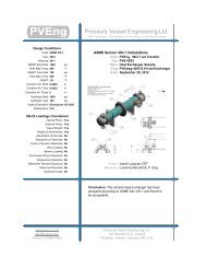
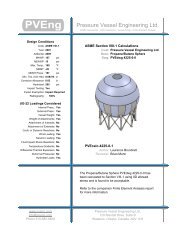
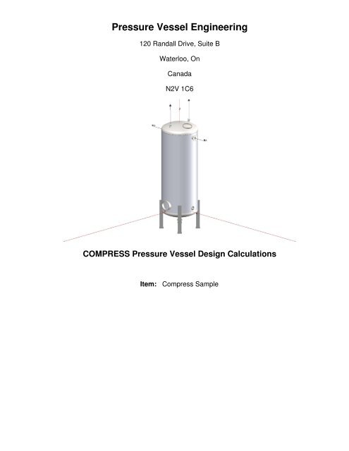
Pressure Vessel Engineering120 Randall Drive, Suite BWaterloo, OnCanadaN2V 1C6COMPRESS Pressure Vessel Design <strong>Calculations</strong>Item: <strong>Compress</strong> Sample
Table Of Contents1. Settings Summary2. Nozzle Schedule3. Nozzle Summary4. Pressure Summary5. Thickness Summary6. Weight Summary7. Hydrostatic Test8. Component Commentary9. Head, Top10. Straight Flange on Head, Top11. Shell12. Inlet (N1)13. Outlet/Drain (N2)14. Vent (N3)15. Process (N4, N5)16. Manway, Top (M1)17. Manway, Shell (M2)18. Straight Flange on Head, Bottom19. Head, Bottom20. Legs21. Seismic Code22. Lifting Lug1/46
Settings SummaryCOMPRESS 2012 Build 7200Units: U.S. CustomaryDatum Line Location: 0.00" from bottom seamDesignASME Section VIII Division 1, 2010 Edition, A11 AddendaDesign or Rating:Minimum thickness:Design for cold shut down only:Design for lethal service (full radiography required):Design nozzles for:Corrosion weight loss:UG-23 Stress Increase: 1.20Skirt/legs stress increase: 1.0Minimum nozzle projection: 1"Juncture calculations for α > 30 only:Preheat P-No 1 Materials > 1.25" and
UG-22 LoadingsUG-22(a) Internal or External Design Pressure :UG-22(b) Weight of the vessel and normal contents under operating or test conditions:UG-22(c) Superimposed static reactions from weight of attached equipment (external loads):UG-22(d)(2) Vessel supports such as lugs, rings, skirts, saddles and legs:UG-22(f) Wind reactions:UG-22(f) Seismic reactions:UG-22(j) Test pressure and coincident static head acting during the test:Note: UG-22(b),(c) and (f) loads only considered when supports are present.YesYesNoYesNoYesYes3/46
Nozzle ScheduleNozzlemarkServiceSizeNozzle Impact NormFineGrainMaterialsPad Impact NormFineGrainFlangeM1 Manway, Top 16" x 12" Elliptical NozzleM2 Manway, Shell 16" x 12" Elliptical NozzleSA-106 B SmlspipeSA-106 B SmlspipeNo No No N/A N/A N/A N/A N/ANo No No N/A N/A N/A N/A N/AN1 Inlet NPS 4 Sch 160SA-106 B SmlspipeNo No No N/A N/A N/A N/ASO A105 Class150N2 Outlet/Drain NPS 4 Sch 160SA-106 B SmlspipeNo No No N/A N/A N/A N/ASO A105 Class150N3VentNPS 1 Class 6000 -threadedSA-105 No No No N/A N/A N/A N/A N/AN4, N5 Process 2.44 IDx1.78 SA-240 316 No No No N/A N/A N/A N/A N/A4/46
Nozzle SummaryNozzlemarkOD(in)t n(in)Req t n(in)A 1 ? A 2 ?Nom t(in)ShellDesign t(in)User t(in)ReinforcementPadWidth(in)t pad(in)Corr(in)A a/A r(%)M1 18 1 0.0806 Yes Yes 0.68* 0.2269 N/A N/A 0 197.0M2 18 1 0.0829 Yes Yes 0.5 0.2304 N/A N/A 0 238.7N1 4.5 0.531 0.237 Yes Yes 0.5 N/A N/A N/A 0 ExemptN2 4.5 0.531 0.237 Yes Yes 0.68* N/A N/A N/A 0 ExemptN3 2.25 0.4675 0.0938 Yes Yes 0.68* N/A N/A N/A 0 ExemptN4, N5 6 1.78 0.2302 Yes Yes 0.5 N/A N/A N/A 0 Exemptt n: Nozzle thicknessReq t n: Nozzle thickness required per UG-45/UG-16Nom t: Vessel wall thicknessDesign t: Required vessel wall thickness due to pressure + corrosion allowance per UG-37User t: Local vessel wall thickness (near opening)A a: Area available per UG-37, governing conditionA r: Area required per UG-37, governing conditionCorr: Corrosion allowance on nozzle wall* Head minimum thickness after forming5/46
Pressure SummaryPressure Summary for Chamber bounded by Head, Bottom and Head, TopIdentifierPDesign( psi)TDesign( °F)MAWP( psi)MDMT( °F)MDMTExemptionImpactTestedHead, Top 150 120 217.35 -20 Note 1 NoStraight Flange on Head, Top 150 120 429.29 -20 Note 2 NoShell 150 120 230.78 -20 Note 2 NoStraight Flange on Head, Bottom 150 120 425.12 -20 Note 2 NoHead, Bottom 150 120 212.82 -20 Note 3 NoLegs 150 120 150 N/A N/A N/AManway, Top (M1) 150 120 150 -20 Note 4 NoManway, Shell (M2) 150 120 150 -20 Note 5 NoInlet (N1) 150 120 150 -20 Note 6 NoOutlet/Drain (N2) 150 120 150 -20 Note 6 NoVent (N3) 150 120 150 -20 Note 7 NoProcess (N4, N5) 150 120 150 -320Chamber design MDMT is -20 °FChamber rated MDMT is -20 °F @ 150 psiNozzle N/A NoPad Note 8 NoChamber MAWP hot & corroded is 150 psi @ 120 °FThis pressure chamber is not designed for external pressure.Notes for Maximum Pressure Rating:Note #Details1.Option to calculate MAP was not selected. See the Calculation->General tab of the Set Modedialog.Notes for MDMT Rating:Note # Exemption Details1. Straight Flange governs MDMT2. Material is impact test exempt per UG-20(f) UCS-66 governing thickness = 0.5 in3. Straight Flange governs MDMT4. Nozzle is impact test exempt per UG-20(f) UCS-66 governing thickness = 0.68 in.5. Nozzle is impact test exempt per UG-20(f) UCS-66 governing thickness = 0.5 in.6. Nozzle is impact test exempt per UG-20(f) UCS-66 governing thickness = 0.4646 in.7. Nozzle is impact test exempt per UG-20(f) UCS-66 governing thickness = 0.4675 in.8. Rated MDMT per UHA-51(d)(1)(a) = -320 °FDesign notes are available on the Settings Summary page.6/46
Thickness SummaryComponentIdentifierMaterialDiameter(in)Length(in)Nominal t(in)Design t(in)Total Corrosion(in)JointELoadHead, Top SA-516 70 60 OD 10.486 0.68* 0.4708 0 0.85 InternalStraight Flange on Head, Top SA-516 70 60 OD 1.5 0.75 0.2638 0 0.85 InternalShell SA-516 70 60 OD 120 0.5 0.3288 0 0.70 InternalStraight Flange on Head, Bottom SA-516 70 60 OD 1.5 0.75 0.2711 0 0.85 InternalHead, Bottom SA-516 70 60 OD 10.486 0.68* 0.4849 0 0.85 InternalNominal t: Vessel wall nominal thicknessDesign t: Required vessel thickness due to governing loading + corrosionJoint E: Longitudinal seam joint efficiency* Head minimum thickness after formingLoadinternal:external:Wind:Seismic:Circumferential stress due to internal pressure governsExternal pressure governsCombined longitudinal stress of pressure + weight + wind governsCombined longitudinal stress of pressure + weight + seismic governs7/46
Weight SummaryComponentMetalNew*MetalCorroded* InsulationWeight ( lb) Contributed by Vessel ElementsInsulationSupports Lining Piping+ LiquidOperating LiquidTest LiquidNew Corroded New CorrodedHead, Top 656 656 0 0 0 0 0 0 737.1 737.1 25Shell 3,139.7 3,139.7 0 0 0 0 11,265.9 11,265.9 11,858.9 11,858.9 155Head, Bottom 691.8 691.8 0 0 0 0 734.4 734.4 734.4 734.4 26Legs 252.2 252.2 0 0 0 0 0 0 0 0 43TOTAL: 4,739.8 4,739.8 0 0 0 0 12,000.2 12,000.2 13,330.4 13,330.4 249* Shells with attached nozzles have weight reduced by material cut out for opening.Surface Areaft2ComponentBody FlangesNozzles &FlangesNew Corroded New CorrodedWeight ( lb) Contributed by AttachmentsPackedBedsLadders &PlatformsTraysTraySupportsRings &ClipsVerticalLoadsSurface Areaft2Head, Top 0 0 43.2 43.2 0 0 0 0 6.8 0 1Shell 0 0 77.1 77.1 0 0 0 0 0 0 2Head, Bottom 0 0 24.5 24.5 0 0 0 0 0 0 1Legs 0 0 0 0 0 0 0 0 0 0 0TOTAL: 0 0 144.8 144.8 0 0 0 0 6.8 0 4Vessel operating weight, Corroded: 16,892 lbVessel operating weight, New: 16,892 lbVessel empty weight, Corroded: 4,891 lbVessel empty weight, New: 4,891 lbVessel test weight, New:18,222 lbVessel test weight, Corroded: 18,222 lbVessel surface area: 253 ft 2Vessel center of gravity location - from datum - lift conditionVessel Lift Weight, New: 4,891 lbCenter of Gravity: 56.2798"Vessel CapacityVessel Capacity** (New):1,596 US galVessel Capacity** (Corroded): 1,596 US gal**The vessel capacity does not include volume of nozzle, piping or other attachments.8/46
Hydrostatic TestShop test pressure determination for Chamber bounded by Head, Bottom and Head, Top based on MAWP perUG-99(b)Shop hydrostatic test gauge pressure is 195 psi at 70 °F (the chamber MAWP = 150 psi)The shop test is performed with the vessel in the horizontal position.IdentifierLocal testpressurepsiTest liquidstatic headpsiUG-99(b)stressratioUG-99(b)pressurefactorStressduring testpsiAllowabletest stresspsiStressexcessive?Head, Top (1) 197.358 2.358 1 1.30 8,707 34,200 NoStraight Flange on Head, Top 197.355 2.355 1 1.30 7,795 34,200 NoShell 197.364 2.364 1 1.30 11,743 34,200 NoStraight Flange on Head, Bottom 197.355 2.355 1 1.30 7,795 34,200 NoHead, Bottom 197.358 2.358 1 1.30 8,707 34,200 NoInlet (N1) 195.217 0.217 1 1.30 14,130 51,300 NoManway, Shell (M2) 196.588 1.588 1 1.30 11,599 51,300 NoManway, Top (M1) 195.65 0.65 1 1.30 26,681 51,300 NoOutlet/Drain (N2) 196.362 1.362 1 1.30 10,266 51,300 NoProcess (N4, N5) 195.217 0.217 1 1.30 5,060 51,300 NoVent (N3) 196.323 1.323 1 1.30 8,926 51,300 NoNotes:(1) Head, Top limits the UG-99(b) stress ratio.(2) P Lstresses at nozzle openings have been estimated using the method described in PVP-Vol. 399, pages 77-82.(3) 1.5*0.9*S yused as the basis for the maximum local primary membrane stress at the nozzle intersection P L.(4) The zero degree angular position is assumed to be up, and the test liquid height is assumed to the top-mostflange.The field test condition has not been investigated for the Chamber bounded by Head, Bottom and Head, Top.The test temperature of 70 °F is warmer than the minimum recommended temperature of 10 °F so the brittle fractureprovision of UG-99(h) has been met.9/46
Component Commentary ReportCommentary for Head, BottomCommentary for Head, Bottom:Top and Bottom head are Post Formed Heat Treated per UCS-79(d)Back to top10/46
Head, TopASME Section VIII, Division 1, 2010 Edition, A11 AddendaComponent:F&D HeadMaterial Specification: SA-516 70 (II-D p.18, ln. 19)Straight Flange governs MDMTInternal design pressure: P = 150 psi @ 120 °FStatic liquid head:P s= 0 psi (SG=1, H s=0" Operating head)P th= 2.36 psi (SG=1, H s=65.32" Horizontal test head)Corrosion allowance: Inner C = 0" Outer C = 0"Design MDMT = -20°FRated MDMT = -20°FNo impact test performedMaterial is not normalizedMaterial is not produced to fine grain practicePWHT is not performedDo not Optimize MDMT / Find MAWPRadiography: Category A joints - Seamless No RTHead to shell seam - None UW-11(c) Type 1Estimated weight*: new = 656 lbcorr = 656 lbCapacity*: new = 87.9 US gal corr = 87.9 US gal* includes straight flangeOuter diameter = 60"Crown radius L = 60"Knuckle radius r = 3.6"Minimum head thickness = 0.68"Straight flange length L sf= 1.5"Nominal straight flange thickness t sf= 0.75"Results SummaryThe governing condition is internal pressure.Minimum thickness per UG-16 = 0.0938" + 0" = 0.0938"Design thickness due to internal pressure (t) = 0.4708"Maximum allowable working pressure (MAWP) = 217.35 psiM (Corroded)M=1/4*[3 + (L / r) 1/2 ]=1/4*[3 + (60 / 3.6) 1/2 ]=1.770621M (New)M=1/4*[3 + (L / r) 1/2 ]=1/4*[3 + (60 / 3.6) 1/2 ]=1.770621Design thickness for internal pressure, (Corroded at 120 °F) Appendix 1-4(d)t = P*L o*M / (2*S*E + P*(M - 0.2)) + Corrosion11/46
= 150*60.68*1.7706 / (2*20,000*0.85 + 150*(1.7706 - 0.2)) + 0= 0.4707"The head internal pressure design thickness is 0.4708".Maximum allowable working pressure, (Corroded at 120 °F) Appendix 1-4(d)P = 2*S*E*t / (M*L o- t*(M - 0.2)) - P s= 2*20,000*0.85*0.68 / (1.7706*60.68 - 0.68*(1.7706 - 0.2)) - 0= 217.35 psiThe maximum allowable working pressure (MAWP) is 217.35 psi.% Extreme fiber elongation - UCS-79(d)EFE = (75*t / R f)*(1 - R f/ R o)= (75*0.75 / 3.975)*(1 - 3.975 / ∞)= 14.1509%The extreme fiber elongation exceeds 5 percent and the thickness exceeds 5/8 inch;. Heat treatment per UCS-56 isrequired if fabricated by cold forming.12/46
Straight Flange on Head, TopASME Section VIII Division 1, 2010 Edition, A11 AddendaComponent:Straight FlangeMaterial specification: SA-516 70 (II-D p. 18, ln. 19)Material is impact test exempt per UG-20(f)UCS-66 governing thickness = 0.5 inInternal design pressure: P = 150 psi @ 120 °FStatic liquid head:P s= 0 psi (SG = 1, H s= 0",Operating head)(SG = 1, HP th= 2.36 psis= 65.25", Horizontal testhead)Corrosion allowance Inner C = 0" Outer C = 0"Design MDMT = -20 °FRated MDMT = -20 °FNo impact test performedMaterial is not normalizedMaterial is not produced to Fine Grain PracticePWHT is not performedRadiography: Longitudinal joint - Seamless No RTCircumferential joint - None UW-11(c) Type 1Estimated weight New = 59.3 lbcorr = 59.3 lbCapacity New = 17.45 US gal corr = 17.45 US galOD = 60"LengthL c= 1.5"t = 0.75"Design thickness, (at 120 °F) Appendix 1-1t = P*R o/ (S*E + 0.40*P) + Corrosion= 150*30 / (20,000*0.85 + 0.40*150) + 0= 0.2638"Maximum allowable working pressure, (at 120 °F) Appendix 1-1P = S*E*t / (R o- 0.40*t) - P s= 20,000*0.85*0.75 / (30 - 0.40*0.75) - 0= 429.29 psi% Extreme fiber elongation - UCS-79(d)EFE = (50*t / R f)*(1 - R f/ R o)= (50*0.75 / 29.625)*(1 - 29.625 / ∞)= 1.2658%The extreme fiber elongation does not exceed 5%.13/46
Design thickness = 0.2638"The governing condition is due to internal pressure.The cylinder thickness of 0.75" is adequate.Thickness Required Due to Pressure + External LoadsConditionPressure P (psi)AllowableStress BeforeUG-23 StressIncrease ( psi)Temperature (°F)Corrosion C(in)LoadReq'd Thk Due toTension (in)Req'd Thk Due to<strong>Compress</strong>ion (in)S tS cOperating, Hot & Corroded 150 20,000 16,284 120 0 Seismic 0.1303 0.1301Operating, Hot & New 150 20,000 16,284 120 0 Seismic 0.1303 0.1301Hot Shut Down, Corroded 0 20,000 16,284 120 0 Seismic 0.0001 0.0003Hot Shut Down, New 0 20,000 16,284 120 0 Seismic 0.0001 0.0003Empty, Corroded 0 20,000 16,284 70 0 Seismic 0.0001 0.0002Empty, New 0 20,000 16,284 70 0 Seismic 0.0001 0.0002Hot Shut Down, Corroded, Weight& Eccentric Moments Only0 20,000 16,284 120 0 Weight 0.0002 0.000214/46
ShellASME Section VIII Division 1, 2010 Edition, A11 AddendaComponent:CylinderMaterial specification: SA-516 70 (II-D p. 18, ln. 19)Material is impact test exempt per UG-20(f)UCS-66 governing thickness = 0.5 inInternal design pressure: P = 150 psi @ 120 °FStatic liquid head:P s= 4.12 psi (SG = 1, H s= 114",Operating head)P th=(SG = 1, H2.36 psis= 65.5", Horizontal testhead)Corrosion allowance Inner C = 0" Outer C = 0"Design MDMT = -20 °FRated MDMT = -20 °FNo impact test performedMaterial is not normalizedMaterial is not produced to Fine Grain PracticePWHT is not performedRadiography: Longitudinal joint - None UW-11(c) Type 1Top circumferential joint - None UW-11(c) Type 1Bottom circumferential joint - None UW-11(c) Type 1Estimated weight New = 3,139.7 lbcorr = 3,139.7 lbCapacity New = 1,420.24 US gal corr = 1,420.24 US galOD = 60"LengthL c= 120"t = 0.5"Design thickness, (at 120 °F) Appendix 1-1t = P*R o/ (S*E + 0.40*P) + Corrosion= 154.12*30 / (20,000*0.70 + 0.40*154.12) + 0= 0.3288"Maximum allowable working pressure, (at 120 °F) Appendix 1-1P = S*E*t / (R o- 0.40*t) - P s= 20,000*0.70*0.5 / (30 - 0.40*0.5) - 4.12= 230.78 psi% Extreme fiber elongation - UCS-79(d)EFE = (50*t / R f)*(1 - R f/ R o)= (50*0.5 / 29.75)*(1 - 29.75 / ∞)= 0.8403%The extreme fiber elongation does not exceed 5%.15/46
Design thickness = 0.3288"The governing condition is due to internal pressure.The cylinder thickness of 0.5" is adequate.Thickness Required Due to Pressure + External LoadsConditionPressure P (psi)AllowableStress BeforeUG-23 StressIncrease ( psi)Temperature (°F)Corrosion C(in)LocationLoadReq'd Thk Due toTension (in)Req'd Thk Dueto<strong>Compress</strong>ion(in)S tS cOperating, Hot & Corroded 150 20,000 15,117 120 0Operating, Hot & New 150 20,000 15,117 120 0Hot Shut Down, Corroded 0 20,000 15,117 120 0Hot Shut Down, New 0 20,000 15,117 120 0Empty, Corroded 0 20,000 15,117 70 0Empty, New 0 20,000 15,117 70 0Top Seismic 0.0954 0.0873Bottom Seismic 0.0952 0.0935Top Seismic 0.0954 0.0873Bottom Seismic 0.0952 0.0935Top Seismic 0.0033 0.0063Bottom Seismic 0.0031 0.0015Top Seismic 0.0033 0.0063Bottom Seismic 0.0031 0.0015Top Seismic 0.0003 0.0023Bottom Seismic 0.0002 0.0001Top Seismic 0.0003 0.0023Bottom Seismic 0.0002 0.0001Hot Shut Down, Corroded,Weight & Eccentric MomentsOnly0 20,000 15,117 120 0Top Weight 0.0013 0.0014Bottom Weight 0.0034 0.003416/46
Inlet (N1)ASME Section VIII Division 1, 2010 Edition, A11 Addendat w(lower)= 0.5 inLeg 41=0.375 inNote: round inside edges per UG-76(c)Located on:ShellLiquid static head included:0.0621 psiNozzle material specification: SA-106 B Smls pipe (II-D p. 10, ln. 40)Nozzle longitudinal joint efficiency: 1Nozzle description: NPS 4 Sch 160Flange description:NPS 4 Class 150 SO A105Bolt Material: SA-193 B7 Bolt
Reinforcement <strong>Calculations</strong> for Internal PressureUG-37 Area Calculation Summary(in 2 )For P = 150.06 psi @ 120 °FArequiredAavailableA 1 A 2 A 3 A 5AweldsThis nozzle is exempt from areacalculations per UG-36(c)(3)(a)UG-45 NozzleWallThicknessSummary (in)The nozzle passesUG-45t reqt min0.2074 0.4646UG-41 Weld Failure Path Analysis SummaryThe nozzle is exempt from weld strength calculationsper UW-15(b)(2)UW-16 Weld Sizing SummaryWeld descriptionRequired weldthroat size (in)Actual weldthroat size (in)StatusNozzle to shell fillet (Leg 41 ) 0.25 0.2625 weld size is adequateThis opening does not require reinforcement per UG-36(c)(3)(a)18/46
Outlet/Drain (N2)ASME Section VIII Division 1, 2010 Edition, A11 Addendat w(lower)= 0.68 inLeg 41=0.375 inNote: round inside edges per UG-76(c)Located on:Head, BottomLiquid static head included:4.7383 psiNozzle material specification: SA-106 B Smls pipe (II-D p. 10, ln. 40)Nozzle longitudinal joint efficiency: 1Nozzle description: NPS 4 Sch 160Flange description:NPS 4 Class 150 SO A105Bolt Material: SA-193 B7 Bolt
Reinforcement <strong>Calculations</strong> for Internal PressureUG-37 Area Calculation Summary(in 2 )For P = 154.74 psi @ 120 °FArequiredAavailableA 1 A 2 A 3 A 5AweldsThis nozzle is exempt from areacalculations per UG-36(c)(3)(a)UG-45 NozzleWallThicknessSummary (in)The nozzle passesUG-45t reqt min0.2074 0.4646UG-41 Weld Failure Path Analysis SummaryThe nozzle is exempt from weld strength calculationsper UW-15(b)(2)UW-16 Weld Sizing SummaryWeld descriptionRequired weldthroat size (in)Actual weldthroat size (in)StatusNozzle to shell fillet (Leg 41 ) 0.25 0.2625 weld size is adequateThis opening does not require reinforcement per UG-36(c)(3)(a)20/46
Vent (N3)ASME Section VIII Division 1, 2010 Edition, A11 Addendat w(lower)= 0.68 inLeg 41=0.375 inNote: round inside edges per UG-76(c)Located on:Head, TopLiquid static head included:0 psiNozzle material specification: SA-105 (II-D p. 18, ln. 5)Nozzle longitudinal joint efficiency: 1Nozzle description:NPS 1 Class 6000 - threadedNozzle orientation: 0°Calculated as hillside:NoLocal vessel minimum thickness: 0.68 inEnd of nozzle to datum line:132.9755 inNozzle inside diameter, new:1.315 inNozzle nominal wall thickness: 0.4675 inNozzle corrosion allowance:0 inProjection available outside vessel, Lpr: 1 inDistance to head center, R:0 inReinforcement <strong>Calculations</strong> for Internal Pressure21/46
UG-37 Area Calculation Summary(in 2 )For P = 150 psi @ 120 °FArequiredAavailableA 1 A 2 A 3 A 5AweldsThis nozzle is exempt from areacalculations per UG-36(c)(3)(a)UG-45 NozzleWallThicknessSummary (in)The nozzle passesUG-45t reqt min0.0938 0.4675UG-41 Weld Failure Path Analysis SummaryThe nozzle is exempt from weld strength calculationsper UW-15(b)(2)UW-16 Weld Sizing SummaryWeld descriptionRequired weldthroat size (in)Actual weldthroat size (in)StatusNozzle to shell fillet (Leg 41 ) 0.25 0.2625 weld size is adequateThis opening does not require reinforcement per UG-36(c)(3)(a)22/46
Process (N4, N5)ASME Section VIII Division 1, 2010 Edition, A11 AddendaPad inner diameter =Pad thickness =Tapped hole diameter =Tapped hole depth =Tapped hole bolt circle =Raised face height =Raised face outer diameter =Inner fillet =t w(lower)=D p=t e=2.44 in1.5 in0.75 in1.125 in4.75 in0 in5.4725 in0.375 in0.5 in6 in1 inNote: round inside edges per UG-76(c)Note: Thread engagement shall comply with the requirements of UG-43(g).Located on:ShellLiquid static head included:3.9425 psiNozzle material specification: SA-240 316 (II-D p. 70, ln. 26)Bolt material specification: SA-193 B7 Bolt
UG-37 Area Calculation Summary(in 2 )For P = 153.94 psi @ 120 °FArequiredAavailableA 1 A 2 A 3 A 5AweldsThis nozzle is exempt from areacalculations per UG-36(c)(3)(a)UG-45Nozzle WallThicknessSummary(in)The nozzlepasses UG-45t reqt min0.2302 1.78UG-41 Weld Failure Path Analysis SummaryThe nozzle is exempt from weld strength calculationsper UW-15(b)(2)UW-16 Weld Sizing SummaryWeld descriptionRequired weldthroat size (in)Actual weldthroat size (in)StatusPad to shell fillet (Leg 42 ) 0.25 0.2625 weld size is adequateThis opening does not require reinforcement per UG-36(c)(3)(a)24/46
Manway, Top (M1)ASME Section VIII Division 1, 2010 Edition, A11 Addendat w(lower)= 0.68 inLeg 41= 0.375 inLeg 43= 0 inh new= 0.75 inNote: round inside edges per UG-76(c)Located on:Head, TopLiquid static head included:0 psiNozzle material specification: SA-106 B Smls pipe (II-D p. 10, ln. 40)Nozzle longitudinal joint efficiency: 1Nozzle description:16" x 12" Elliptical NozzleElliptical manway pressure rating: 300 psi @ 650 °FNozzle orientation: 0°Calculated as hillside:NoLocal vessel minimum thickness: 0.68 inUser input radial limit of reinforcement: 12 inEnd of nozzle to datum line:130.0463 inNozzle inside diameter, new:16 inNozzle nominal wall thickness: 1 inNozzle corrosion allowance:0 inProjection available outside vessel, Lpr: 1.5 inInternal projection, h new:0.75 inDistance to head center, R:18 inReinforcement <strong>Calculations</strong> for Internal Pressure25/46
UG-37 Area Calculation Summary (in 2 )For P = 150 psi @ 120 °FThe opening is adequately reinforcedUG-45 NozzleWallThicknessSummary (in)The nozzle passesUG-45ArequiredAavailableA 1 A 2 A 3 A 5Awelds3.6957 7.2805 3.4936 2.3842 1.2825 -- 0.1202 0.0705 0.875t reqt minUG-41 Weld Failure Path Analysis SummaryThe nozzle is exempt from weld strength calculationsper UW-15(b)(1)UW-16 Weld Sizing SummaryWeld descriptionRequired weldthroat size (in)Actual weldthroat size (in)StatusNozzle to shell fillet (Leg 41 ) 0.25 0.2625 weld size is adequate26/46
Manway, Shell (M2)ASME Section VIII Division 1, 2010 Edition, A11 Addendat w(lower)= 0.5 inLeg 41= 0.375 inLeg 43= 0 inh new= 0.875 inNote: round inside edges per UG-76(c)Located on:ShellLiquid static head included:4.0429 psiNozzle material specification: SA-106 B Smls pipe (II-D p. 10, ln. 40)Nozzle longitudinal joint efficiency: 1Nozzle description:16" x 12" Elliptical NozzleElliptical manway pressure rating: 300 psi @ 650 °FNozzle orientation: 90°Local vessel minimum thickness: 0.5 inNozzle center line offset to datum line: 10 inEnd of nozzle to shell center:32.625 inNozzle inside diameter, new:16 inNozzle nominal wall thickness: 1 inNozzle corrosion allowance:0 inProjection available outside vessel, Lpr: 2.625 inInternal projection, h new:0.875 inReinforcement <strong>Calculations</strong> for Internal Pressure27/46
UG-37 Area Calculation Summary (in 2 )For P = 154.04 psi @ 120 °FThe opening is adequately reinforcedUG-45 NozzleWallThicknessSummary (in)The nozzle passesUG-45ArequiredAavailableA 1 A 2 A 3 A 5Awelds1.8762 9.6446 6.0456 1.9825 1.4963 -- 0.1202 0.0725 0.875t reqt minUG-41 Weld Failure Path Analysis SummaryThe nozzle is exempt from weld strength calculationsper UW-15(b)(1)UW-16 Weld Sizing SummaryWeld descriptionRequired weldthroat size (in)Actual weldthroat size (in)StatusNozzle to shell fillet (Leg 41 ) 0.25 0.2625 weld size is adequateReinforcement check in the plane parallel to the longitudinal axisReinforcement <strong>Calculations</strong> for Internal PressureUG-37 Area Calculation Summary (in 2 )For P = 154.04 psi @ 120 °FThe opening is adequately reinforcedUG-45 NozzleWallThicknessSummary (in)The nozzle passesUG-45ArequiredAavailableA 1 A 2 A 3 A 5Awelds2.831 6.7566 3.1576 1.9825 1.4963 -- 0.1202 0.0725 0.875t reqt minUG-41 Weld Failure Path Analysis SummaryThe nozzle is exempt from weld strength calculationsper UW-15(b)(1)UW-16 Weld Sizing SummaryWeld descriptionRequired weldthroat size (in)Actual weldthroat size (in)StatusNozzle to shell fillet (Leg 41 ) 0.25 0.2625 weld size is adequate28/46
Straight Flange on Head, BottomASME Section VIII Division 1, 2010 Edition, A11 AddendaComponent:Straight FlangeMaterial specification: SA-516 70 (II-D p. 18, ln. 19)Material is impact test exempt per UG-20(f)UCS-66 governing thickness = 0.5 inInternal design pressure: P = 150 psi @ 120 °FStatic liquid head:P s= 4.17 psi (SG = 1, H s= 115.5",Operating head)P th=(SG = 1, H2.36 psis= 65.25", Horizontal testhead)Corrosion allowance Inner C = 0" Outer C = 0"Design MDMT = -20 °FRated MDMT = -20 °FNo impact test performedMaterial is not normalizedMaterial is not produced to Fine Grain PracticePWHT is not performedRadiography: Longitudinal joint - Seamless No RTCircumferential joint - None UW-11(c) Type 1Estimated weight New = 59.3 lbcorr = 59.3 lbCapacity New = 17.45 US gal corr = 17.45 US galOD = 60"LengthL c= 1.5"t = 0.75"Design thickness, (at 120 °F) Appendix 1-1t = P*R o/ (S*E + 0.40*P) + Corrosion= 154.17*30 / (20,000*0.85 + 0.40*154.17) + 0= 0.2711"Maximum allowable working pressure, (at 120 °F) Appendix 1-1P = S*E*t / (R o- 0.40*t) - P s= 20,000*0.85*0.75 / (30 - 0.40*0.75) - 4.17= 425.12 psi% Extreme fiber elongation - UCS-79(d)EFE = (50*t / R f)*(1 - R f/ R o)= (50*0.75 / 29.625)*(1 - 29.625 / ∞)= 1.2658%The extreme fiber elongation does not exceed 5%.29/46
Design thickness = 0.2711"The governing condition is due to internal pressure.The cylinder thickness of 0.75" is adequate.Thickness Required Due to Pressure + External LoadsConditionPressure P (psi)AllowableStress BeforeUG-23 StressIncrease ( psi)Temperature (°F)Corrosion C(in)LoadReq'd Thk Due toTension (in)Req'd Thk Due to<strong>Compress</strong>ion (in)S tS cOperating, Hot & Corroded 150 20,000 16,284 120 0 Seismic 0.1347 0.1324Operating, Hot & New 150 20,000 16,284 120 0 Seismic 0.1347 0.1324Hot Shut Down, Corroded 0 20,000 16,284 120 0 Seismic 0.0044 0.0021Hot Shut Down, New 0 20,000 16,284 120 0 Seismic 0.0044 0.0021Empty, Corroded 0 20,000 16,284 70 0 Seismic 0.0003 0.0001Empty, New 0 20,000 16,284 70 0 Seismic 0.0003 0.0001Hot Shut Down, Corroded, Weight& Eccentric Moments Only0 20,000 16,284 120 0 Weight 0.0048 0.004830/46
Head, BottomASME Section VIII, Division 1, 2010 Edition, A11 AddendaComponent:F&D HeadMaterial Specification: SA-516 70 (II-D p.18, ln. 19)Straight Flange governs MDMTInternal design pressure: P = 150 psi @ 120 °FStatic liquid head:P s= 4.52 psi (SG=1, H s=125.306" Operating head)P th= 2.36 psi (SG=1, H s=65.32" Horizontal test head)Corrosion allowance: Inner C = 0" Outer C = 0"Design MDMT = -20°FRated MDMT = -20°FNo impact test performedMaterial is not normalizedMaterial is not produced to fine grain practicePWHT is not performedDo not Optimize MDMT / Find MAWPRadiography: Category A joints - Seamless No RTHead to shell seam - None UW-11(c) Type 1Estimated weight*: new = 691.8 lb corr = 691.8 lbCapacity*: new = 87.9 US gal corr = 87.9 US gal* includes straight flangeOuter diameter = 60"Crown radius L = 60"Knuckle radius r = 3.6"Minimum head thickness = 0.68"Straight flange length L sf= 1.5"Nominal straight flange thickness t sf= 0.75"See Component CommentaryResults SummaryThe governing condition is internal pressure.Minimum thickness per UG-16 = 0.0938" + 0" = 0.0938"Design thickness due to internal pressure (t) = 0.4849"Maximum allowable working pressure (MAWP) = 212.82 psiM (Corroded)M=1/4*[3 + (L / r) 1/2 ]=1/4*[3 + (60 / 3.6) 1/2 ]=1.770621M (New)M=1/4*[3 + (L / r) 1/2 ]=1/4*[3 + (60 / 3.6) 1/2 ]=1.77062131/46
Design thickness for internal pressure, (Corroded at 120 °F) Appendix 1-4(d)t = P*L o*M / (2*S*E + P*(M - 0.2)) + Corrosion= 154.52*60.68*1.7706 / (2*20,000*0.85 + 154.52*(1.7706 - 0.2)) + 0= 0.4848"The head internal pressure design thickness is 0.4849".Maximum allowable working pressure, (Corroded at 120 °F) Appendix 1-4(d)P = 2*S*E*t / (M*L o- t*(M - 0.2)) - P s= 2*20,000*0.85*0.68 / (1.7706*60.68 - 0.68*(1.7706 - 0.2)) - 4.52= 212.82 psiThe maximum allowable working pressure (MAWP) is 212.82 psi.% Extreme fiber elongation - UCS-79(d)EFE = (75*t / R f)*(1 - R f/ R o)= (75*0.75 / 3.975)*(1 - 3.975 / ∞)= 14.1509%The extreme fiber elongation exceeds 5 percent and the thickness exceeds 5/8 inch;. Heat treatment per UCS-56 isrequired if fabricated by cold forming.32/46
LegsLeg material:SA G40.21 44WLeg description:W 6x15 (Flangein)Number of legs: N = 4Overall length: 42 inBase to girth seam length: 30 inBolt circle: 64 inAnchor bolt size: 0.75inch series 8threadedAnchor bolt material:SA-193 B7Anchor bolts/leg: 2Anchor bolt allowable stress: S b= 20,000 psiAnchor bolt corrosion allowance: 0 inAnchor bolt hole clearance: 0.375 inBase plate width: 7 inBase plate length: 7 inBase plate thickness: 0.75Base plate allowable stress: 24,000 psiFoundation allowable bearing stress: 1,658 psiUser defined leg eccentricity: 0 inEffective length coefficient: K = 1.2Coefficient: C m= 0.85Leg yield stress: F y= 36,000 psiLeg elastic modulus: E = 29,000,000 psiLeg to shell fillet weld: 0.25Legs braced:Noin (0.1779 inrequired)in (0.0547 inrequired)Note: The support attachment point is assumed to be 1 in up from the cylinder circumferential seam.Conditions Investigated (Only Governing Condition Reported)33/46
Weight operating corrodedWeight empty corrodedSeismic operating corrodedSeismic empty corrodedLoadingForceattackangle °Legposition °Axialend loadlb fShearresistedlb fAxialf apsiBendingf bxpsiBendingf bypsiRatioH 1-1RatioH 1-2GoverningConditionSeismicoperatingcorrodedMoment =20,988.2 lb f -ft045560 -2,051.2 430.2 -463 3,940 0 0.1180 0.144490 4,509.3 1,343.4 1,018 0 3,940 0.1911 0.2130180 8,706.9 430.2 1,965 3,940 0 0.2385 0.2568270 4,509.3 1,343.4 1,018 0 3,940 0.1911 0.21300 -2,051.2 886.8 -463 5,743 1,839 0.2481 0.297790 -2,051.2 886.8 -463 5,743 1,839 0.2481 0.2977180 8,706.9 886.8 1,965 5,743 1,839 0.3694 0.4101270 8,706.9 886.8 1,965 5,743 1,839 0.3694 0.41010 -2,051.2 1,057.8 -463 5,418 2,572 0.2627 0.314890 -2,051.2 715.8 -463 5,435 1,174 0.2133 0.2567180 8,706.9 1,057.8 1,965 5,418 2,572 0.3839 0.4273270 8,706.9 715.8 1,965 5,435 1,174 0.3344 0.3691Leg <strong>Calculations</strong> (AISC manual ninth edition)Axial end load, P 1(Based on vessel total bending moment acting at leg attachment elevation)34/46
P 1= (1 + 0.14*S DS)*W t/ N + 48*M t/ (N*D)= (1 + 0.14*0.6)*16,639.39 / 4 + 48*20,988.2 / ( 4*60)= 8,706.92 lb fAllowable axial compressive stress, F a(AISC chapter E)C c= Sqr(2*π 2 *E / F y)= Sqr(2*π 2 *29,000,000 / 36,000)= 126.0993K*l / r = 1.2*28.5 / 1.4505 = 23.5787F a= 1 * (1 - (K*l / r) 2 / (2*C c2))*F y/ (5 / 3 + 3*(K*l / r) / (8*C c)-(K*l / r) 3 / (8*C c3))= 1 * (1 - (23.5787) 2 / (2*126.0993 2 ))*36,000 / (5 / 3 + 3*(23.5787) / (8*126.0993)-(23.5787) 3 / (8*126.0993 3 ))= 20,375 psiAllowable axial compression and bending (AISC chapter H)F ' ex = 1*12*π2 *E / (23*(K*l / r) 2 )= 1*12*π 2 *29,000,000 / (23*(23.5787) 2 )= 268,603 psiF ' ey = 1*12*π2 *E / (23*(K*l / r) 2 )= 1*12*π 2 *29,000,000 / (23*(13.3439) 2 )= 838,664 psiF b= 1*0.66*F y= 1*0.66*36,000= 23,760 psi<strong>Compress</strong>ive axial stressf a= P 1/ A= 8,706.92 / 4.43= 1,965 psiBending stressesf bx= F*cos(α)*L / (I x/ C x) + P 1*E cc/ (I x/ C x)= 1,057.84*cos(56)*28.5 / (9.32 / 2.995) + 8,706.92*0 / (9.32 / 2.995)= 5,418 psif by= F*sin(α)*L / (I y/ C y)= 1,057.84*sin(56)*28.5 / (29.1 / 3)= 2,572 psiAISC equation H 1-1H 1-1= f a/ F a+ C mx*f bx/ ((1 - f a/ F ' ex )*F bx ) + C my *f by / ((1 - f a / F' ey )*F by )= 1,965 / 20,375 + 0.85*5,418 / ((1 - 1,965 / 268,603)*23,760) + 0.85*2,572 / ((1 - 1,965 / 838,664)*23,760)= 0.3839AISC equation H 1-2H 1-2= f a/ (0.6*1*F y) + f bx/ F bx+ f by/ F by= 1,965 / (0.6*1*36,000) + 5,418 / 23,760 + 2,572 / 23,760= 0.427335/46
4, W 6x15 legs are adequate.Anchor bolts - Seismic operating corroded condition governsTensile loading per leg (2 bolts per leg)R = 48*M / (N*BC) - (0.6 - 0.14*S DS)*W / N= 48*29,844.6 / (4*64) - (0.6 - 0.14*0.6)*16,891.61 / 4= 3,416.84 lb fRequired area per boltA b= R / (S b*n)= 3,416.84 / (20,000*2)= 0.0854 in 2Area of a 0.75 inch series 8 threaded bolt (corroded) = 0.302 in 20.75 inch series 8 threaded bolts are satisfactory.Check the leg to vessel fillet weld, Bednar 10.3, Seismic operating corroded governsNote: continuous welding is assumed for all support leg fillet welds.The following leg attachment weld analysis assumes the fillet weld is present on three sides (leg top closure plate isused).Z w= (2*b*d + d 2 ) / 3= (2*5.99*13.5 + 13.5 2 ) / 3= 114.66 in 2J w= (b + 2*d) 3 / 12 - d 2 *(b + d) 2 / (b + 2*d)= (5.99 + 2*13.5) 3 / 12 - 13.5 2 *(5.99 + 13.5) 2 / (5.99 + 2*13.5)= 893.5287 in 3E = d 2 / (b + 2*d)= 13.5 2 / (5.99 + 2*13.5)= 5.524401 inGoverning weld load f x= Cos(56)*1,057.84 = 591.54 lb fGoverning weld load f y= Sin(56)*1,057.84 = 876.99 lb ff 1= P 1/ L weld= 8,706.92 / 32.99= 263.93 lb f/in (V Ldirect shear)f 2= f y*L leg*0.5*b / J w= 876.99*28.5*0.5*5.99 / 893.5287= 83.78 lb f/in (V Ltorsion shear)f 3= f y/ L weld= 876.99 / 32.99= 26.58 lb f/in (V cdirect shear)f 4= f y*L leg*E / J w= 876.99*28.5*5.5244 / 893.528736/46
= 154.53 lb f/in (V ctorsion shear)f 5= (f x*L leg+ P 1*E cc) / Z w= (591.54*28.5 + 8,706.92*0) / 114.66= 147.03 lb f/in (M Lbending)f 6= f x/ L weld= 591.54 / 32.99= 17.93 lb f/in (Direct outward radial shear)f = Sqr((f 1+ f 2) 2 + (f 3+ f 4) 2 + (f 5+ f 6) 2 )= Sqr((263.93 + 83.78) 2 + (26.58 + 154.53) 2 + (147.03 + 17.93) 2 )= 425.34 lb f/in (Resultant shear load)Required leg to vessel fillet weld leg size (welded both sides + top)t w= f / (0.707*0.55*S a)= 425.34 / (0.707*0.55*20,000)= 0.0547 inThe 0.25 in leg to vessel attachment fillet weld size is adequate.Base plate thickness check, AISC 3-106f p= P / (B*N)= 10,173.49 / (7*7)= 208 psim = (N - 0.95*d) / 2= (7 - 0.95*5.99) / 2= 0.6548 inn = (B - 0.8*b) / 2= (7 - 0.8*5.99) / 2= 1.104 inL = 0.5*(d + b) / 2 - Sqr((0.5*(d + b)) 2 / 4 - P / (4*F p))= 0.5*(5.99 + 5.99) / 2 - Sqr((0.5*(5.99 + 5.99)) 2 / 4 - 10,173.49 / (4*1,658))= 0.2681 int b= Largest(m, n, L)*Sqr(3*f p/ S b)= 1.104*Sqr(3*208 / 24,000)= 0.1779 inThe base plate thickness is adequate.Check the leg to vessel attachment stresses, WRC-107 (Seismic operating corrodedgoverns)Applied LoadsRadial load: P r= -627.07 lb fCircumferential moment: M c= 0 lb f-inCircumferential shear: V c= 0 lb fLongitudinal moment: M L= 17,871.47lb f-inLongitudinal shear: V L= -2,051.16 lb f37/46
Torsion moment: M t= 0 lb f-inInternal pressure: P = 154.115 psiMean shell radius: R m= 29.75 inLocal shell thickness: t = 0.5 inShell yield stress: S y= 37,100 psi38/46
Maximum stresses due to the applied loads at the leg edge (includes pressure)R m/ t = 29.75 / 0.5 = 59.5C 1= 2.995, C 2= 10.715 inLocal circumferential pressure stress = P*R i/ t =9,093 psiLocal longitudinal pressure stress = P*R i/ (2*t) =4,546 psiMaximum combined stress (P L+P b+Q) = 11,895 psiAllowable combined stress (P L+P b+Q) = +-3*S = +-60,000 psiThe maximum combined stress (P L+P b+Q) is within allowable limits.Maximum local primary membrane stress (P L) = 9,923 psiAllowable local primary membrane (P L) = +-1.5*S = +-30,000 psiThe maximum local primary membrane stress (P L) is within allowable limits.Stresses at the leg edge per WRC Bulletin 107Figure value β A uA lB uB lC uC lD uD l3C* 2.7826 0.2782 0 0 0 0 117 117 117 1174C* 7.1219 0.227 300 300 300 300 0 0 0 01C 0.0713 0.1685 0 0 0 0 1,073 -1,073 1,073 -1,0732C-1 0.0369 0.1685 555 -555 555 -555 0 0 0 03A* 2.3949 0.154 0 0 0 0 0 0 0 01A 0.0714 0.1858 0 0 0 0 0 0 0 03B* 4.8127 0.2355 -530 -530 530 530 0 0 0 01B-1 0.02 0.2035 -1,417 1,417 1,417 -1,417 0 0 0 0Pressure stress* 9,093 9,093 9,093 9,093 9,093 9,093 9,093 9,093Total circumferential stress 8,001 9,725 11,895 7,951 10,283 8,137 10,283 8,137Primary membranecircumferential stress*8,863 8,863 9,923 9,923 9,210 9,210 9,210 9,2103C* 3.7498 0.227 158 158 158 158 0 0 0 04C* 6.1817 0.2782 0 0 0 0 261 261 261 2611C-1 0.0442 0.2361 665 -665 665 -665 0 0 0 02C 0.0326 0.2361 0 0 0 0 491 -491 491 -4914A* 4.4851 0.154 0 0 0 0 0 0 0 02A 0.0274 0.2392 0 0 0 0 0 0 0 04B* 2.2573 0.2355 -439 -439 439 439 0 0 0 02B-1 0.023 0.273 -1,215 1,215 1,215 -1,215 0 0 0 0Pressure stress* 4,546 4,546 4,546 4,546 4,546 4,546 4,546 4,546Total longitudinal stress 3,715 4,815 7,023 3,263 5,298 4,316 5,298 4,316Primary membranelongitudinal stress*4,265 4,265 5,143 5,143 4,807 4,807 4,807 4,807Shear from M t 0 0 0 0 0 0 0 0Circ shear from V c 0 0 0 0 0 0 0 0Long shear from V L 0 0 0 0 96 96 -96 -96Total Shear stress 0 0 0 0 96 96 -96 -9639/46
Combined stress (P L +P b +Q) 8,001 9,725 11,895 7,951 10,285 8,139 10,285 8,139Note: * denotes primary stress.40/46
Seismic CodeMethod of seismic analysis:Site ClassImportance Factor: I = 1.0000Spectral Response Acceleration at shortperiod (% g)Spectral Response Acceleration at period of 1sec (% g)Response Modification Coeficient from Table15.4-2IBC 2009 ground supported(Seismic analysis in accordance with ASCE 7-05. All paragraph,page, and table references are from ASCE 7-05.)ES s= 75.00%S 1= 3.00%R = 2.0000Acceleration based site co-efficient: F a= 1.2000Velocity based site co-efficient: F v= 3.5000Long-period transition period: T L= 12.0000Redundancy factor: ρ = 1.0000User Defined Vertical AccelerationsConsidered:No12.4.2.3 Basic Load Combinations for Allowable Stress DesignThe following load combinations are considered in accordance with ASCE section 2.4.1:5. D + P + P s+ 0.7E = (1.0 + 0.14S DS)D + P + P s+ 0.7ρQ E8. 0.6D + P + P s+ 0.7E = (0.6 - 0.14S DS)D + P + P s+ 0.7ρQ EWhereDPP s= Dead load= Internal or external pressure load= Static head loadE = Seismic load = E h+/- E v= ρQ E+/- 0.2S DSDVessel CharacteristicsVessel height: 13.4988 ftVessel Weight:Operating, Corroded: 16,892 lbEmpty, Corroded: 4,891 lbPeriod of Vibration CalculationFundamental Period, T:Operating, Corroded: 0.084 sec (f = 12.0 Hz)Empty, Corroded: 0.044 sec (f = 22.6 Hz)The fundamental period of vibration T (above) is calculated using the Rayleigh method of approximation:41/46
T = 2 * PI * Sqr( {Sum(W i* y i2)} / {g * Sum(W i* y i)} ), whereW iis the weight of the i th lumped mass, andy iis its deflection when the system is treated as a cantilever beam.Seismic Shear Reports:Operating, CorrodedEmpty, CorrodedBase Shear <strong>Calculations</strong>Seismic Shear Report: Operating, CorrodedComponentElevation of bottomabove base (in)Elastic modulus E(106 psi)Inertia I(ft4)Seismic shear atBottom (lbf)BendingMoment atBottom(lbf-ft)Head, Top 150 29.2 * 271 201Shell (top) 30 29.2 1.9947 3,374 21,058Legs 0 29.0 0.0037 3,547 29,845Shell (bottom) 30 29.2 1.9947 140 70Head, Bottom 30 29.2 * 130 59*Moment of Inertia I varies over the length of the componentSeismic Shear Report: Empty, CorrodedComponentElevation of bottomabove base (in)Elastic modulus E(106 psi)Inertia I(ft4)Seismic shear atBottom (lbf)BendingMoment atBottom(lbf-ft)Head, Top 150 29.4 * 155 141Shell (top) 30 29.4 1.9947 559 4,267Legs 0 29.0 0.0037 616 5,778Shell (bottom) 30 29.4 1.9947 39 24Head, Bottom 30 29.4 * 38 20*Moment of Inertia I varies over the length of the component11.4.3: Maximum considered earthquake spectral response accelerationThe maximum considered earthquake spectral response acceleration at short period, S MSS MS= F a* S s= 1.2000 * 75.00 / 100 = 0.9000The maximum considered earthquake spectral response acceleration at 1 s period, S M1S M1= F v* S 1= 3.5000 * 3.00 / 100 = 0.105011.4.4: Design spectral response acceleration parametersDesign earthquake spectral response acceleration at short period, S DSS DS= 2 / 3 * S MS= 2 / 3 * 0.9000 = 0.6000Design earthquake spectral response acceleration at 1 s period, S D1S D1= 2 / 3 * S M1= 2 / 3 * 0.1050 = 0.070012.4.2.3: Seismic Load Combinations: Vertical TermFactor is applied to dead load.42/46
<strong>Compress</strong>ive Side: = 1.0 + 0.14 * S DS= 1.0 + 0.14 * 0.6000Tensile Side:= 1.0840= 0.6 - 0.14 * S DS= 0.6 - 0.14 * 0.6000= 0.5160Base Shear <strong>Calculations</strong>Operating, CorrodedEmpty, CorrodedBase Shear <strong>Calculations</strong>: Operating, CorrodedParagraph 15.4.4: Period DeterminationFundamental Period is taken from the Rayleigh method listed previously in this report.T = 0.0835 sec.12.8.1: Calculation of Seismic Response CoefficientC sis the value computed below, bounded by C sMin and C sMax:C sMin is calculated with equation 15.4-1 and shall not be less than 0.03 (see ASCE 7-05 Supplement No. 2); inaddition, if S 1>= 0.6g, C sMin shall not be less than eqn 15.4-2.C sMax calculated with 12.8-3 because (T = 0.0835)
12.4.2.1 Seismic Load Combinations: Horizontal Seismic Load Effect, E hQ E= VE h= 0.7 * ρ * Q E(Only 70% of seismic load considered as per Section 2.4.1)= 0.70 * 1.0000 * 880.45= 616.31 lb44/46
Lifting LugMinimum reportGeometry InputsAttached ToHead, TopMaterial SA-516 70OrientationLongitudinalDistance of Lift Point From Datum 130.8"Angular Position 90.00°Length of Lug, L 5"Height of Lug, H 5"Thickness of Lug, t 0.5"Hole Diameter, d 1.5"Pin Diameter, Dp 1.25"Load Eccentricity, a 10"Distance from Load to Shell or Pad, a 22.5"Weld Size, t w0.25"Load Angle Normal to Vessel, β 19.0000 °Load Angle from Vertical, φ -0.6391 °Intermediate ValuesLoad Factor 1.5000Vessel Weight (new, incl. Load Factor), WLug Weight (new), W lug7337 lb3 lbAllowable Stress, Tensile, σ t19980psiAllowable Stress, Shear, σ s13320psiAllowable Stress, Bearing, σ p29970psiAllowable Stress, Bending, σ b22201psi45/46
Allowable Stress, Weld Shear, τ allowable13320psiAllowable Stress set to 1/3 Sy per ASME B30.20NoSummary ValuesRequired Lift Pin Diameter, d reqd0.4215"Required Lug Thickness, t reqd0.0992"Lug Stress Ratio, σ ratio0.14Weld Shear Stress Ratio, τ ratio0.26Lug DesignLocal StressesAcceptableAcceptable46/46