Loads on Flanges - PVEng
Loads on Flanges - PVEng
Loads on Flanges - PVEng
- No tags were found...

You also want an ePaper? Increase the reach of your titles
YUMPU automatically turns print PDFs into web optimized ePapers that Google loves.
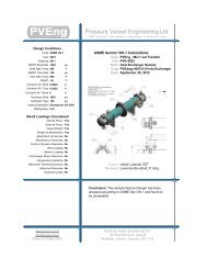
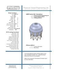
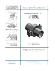
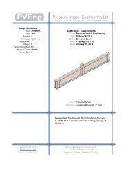
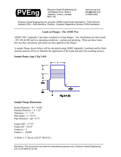
Pressure Vessel Engineering Ltd. provides: ASME Vessel Code Calculati<strong>on</strong>s - Finite ElementAnalysis (FEA) - Solid Modeling / Drafting - Canadian Registrati<strong>on</strong> Number (CRN) Assistance<str<strong>on</strong>g>Loads</str<strong>on</strong>g> <strong>on</strong> <strong>Flanges</strong> - The ASME WayASME VIII-1 Appendix 2 provides a method of sizing flanges. The calculati<strong>on</strong>s use three loads- HT, HG & HD and two operating c<strong>on</strong>diti<strong>on</strong>s - seating and operating. What are these loads,how are they calculated, and where are they applied to the flange?A sample flange shown below will be calculated using ASME Appendix 2 methods and by finiteelement analysis (FEA) to illustrate the applicati<strong>on</strong> of the loads and show the resulting stresses.Sample flange (App 2 Fig 2-4(5)rSample Flange Dimensi<strong>on</strong>sInside Diameter = B = 16.00”Outside Diameter = A = 22”Thickness = t = 1.75Hub radius = r = 0.375Pipe thickness = g0 = 0.75Gasket OD = 17.75”Gasket ID = 16.25”Gasket m = 3Gasket y = 10,00016 Bolts x 1” dia <strong>on</strong> a 20.25” BCD (C)Disclaimer: This document is provided for educati<strong>on</strong>al purposes <strong>on</strong>ly. Pressure Vessel EngineeringLtd. is not liable for its use.
Sample flange - the FEA modelFlange Model16 holes <strong>on</strong> 20.25” BCD, 1” bolt size - <strong>on</strong>ly 1/2 of <strong>on</strong>e bolt will be used for the FEA model dueto symmetry.<str<strong>on</strong>g>Loads</str<strong>on</strong>g> <strong>on</strong> <strong>Flanges</strong>.doc - Page 2 of 16
GasketHalf of the 1” bolt is added. A mirrored body creates a flanged pair.Gasket<str<strong>on</strong>g>Loads</str<strong>on</strong>g>sLocFor FEA the bolt length is cut <strong>on</strong> the center of the gasket. The gasket is removed and is replacedby the loads it generates. Split lines can be seen where the gasket loads HT and HG are applied.<str<strong>on</strong>g>Loads</str<strong>on</strong>g> <strong>on</strong> <strong>Flanges</strong>.doc - Page 3 of 16
Load HD - OperatingHD is created by the pressure <strong>on</strong> the pipe attached to the flange. Force = Pressure x Area.HD = P * B^2 / 4The load is generated <strong>on</strong> center line of the pipe, but the ASME rules change the moment armdepending <strong>on</strong> the attachment method. When FEA is performed, the load should be applied to theattached pipe - the FEA program will determine how the load is distributed.<str<strong>on</strong>g>Loads</str<strong>on</strong>g> <strong>on</strong> <strong>Flanges</strong>.doc - Page 4 of 16
Load HT - OperatingHT is created by the internal pressure acting <strong>on</strong> the gasket:1) Pressure is applied to the exposed edge of the gasket2) The gasket tries to expand but is held in place by the flange faces3) The flange faces push backThe force between the gasket and the flange is shown as a triangle. The force is zero at the ODof the gasket (there is no pressure at the gasket OD and thus no leakage). At the inside edge, thepressure is the pressure in the pipe. HT is the average pressure al<strong>on</strong>g the length. mhT ismeasured at the point 1/3 up the triangle, the centroid of the force.The ASME rules reduce the width of the gasket. This load is a design rule, not a predictor ofactual flange stresses. For FEA analysis, the load HT is applied at the moment arm mhT awayfrom the bolt centerline.<str<strong>on</strong>g>Loads</str<strong>on</strong>g> <strong>on</strong> <strong>Flanges</strong>.doc - Page 5 of 16
Load HG - OperatingHG operating is the force required to keep the flange sealed against the operating pressure. It isgenerated by tightening the bolts. Load = effective area x gasket factor m x Pressure. If theflange is self energizing (does not need additi<strong>on</strong>al force to seal such as an o-ring) then HGoperating = 0Load HG operates through the center of the gasket, but the gasket size is reduced by the ASMErules to create an effective area. Correlati<strong>on</strong> to real gasket properties is difficult - this load andits moment arm is a design rule, not a predictor of actual flange stresses.<str<strong>on</strong>g>Loads</str<strong>on</strong>g> <strong>on</strong> <strong>Flanges</strong>.doc - Page 6 of 16
Load HG - SeatingHG seating is the force required to seat the gasket into the flange gasket face and be leak tightagainst a pressure of 0 psi. (HG operating provides the load required to keep the seal as theoperating pressure is increased).The force HG is loosely based <strong>on</strong> gasket physical properties, but the gasket area used is modified(reduce) from the actual gasket width because the code y factors are too high. Correlati<strong>on</strong> to realgasket properties is impossible - this load and its moment arm are a design rule, not a predictorof actual flange stresses.Force HG has an additi<strong>on</strong>al load added to it - the “gasket destroying” or “gasket crushing” force.The computed seating load <strong>on</strong> the gasket is increased to the average of the required bolt strengthand the available bolt strength. This code disaster greatly increases the required thickness offlanges far bey<strong>on</strong>d the loads that the gasket can handle.As a designer, when the seating loads are too large and are caused by extra bolt area,several opti<strong>on</strong>s are available:1) make the bolts smaller in diameter or fewer in number. Reducing the effective area of thebolts reduces this theoretical gasket crushing force.2) use weaker bolts - same idea as above.3) if material waste and cost are no object, make the flange thicker. This route often is usedwhen a custom appendix 2 flange must mate up to standard flanges such as B16.5 series whichseldom calculate to appendix 2 rules.<str<strong>on</strong>g>Loads</str<strong>on</strong>g> <strong>on</strong> <strong>Flanges</strong>.doc - Page 7 of 16
ASME <str<strong>on</strong>g>Loads</str<strong>on</strong>g> Applied to the FEA ModelHDHG operating+ HG seatingHTThe flange model with the HD, HG and HT loads applied.Combined operating and seating stresses case stresses. Higher stresses can be seen at the pipe toflange disc<strong>on</strong>tinuity. Bending stresses can also be seen in the bolt. Although the stresses lookhigh compared with the 20,000 psi membrane allowable stress for the flange and pipe, thestresses are minor if compared with a local disc<strong>on</strong>tinuity limit of 3x20,000 psi. This flangedesign although loaded to the maximum ASME allows can be c<strong>on</strong>sidered to be lightly loadedand wasteful of materials.<str<strong>on</strong>g>Loads</str<strong>on</strong>g> <strong>on</strong> <strong>Flanges</strong>.doc - Page 8 of 16
Operating loads <strong>on</strong>ly - used for cycle life calculati<strong>on</strong>s (seating HG is removed). The gasket getsseated <strong>on</strong>ce, this is the load that the flange sees with each applicati<strong>on</strong> and removal of pressure.The flange loads are extremely light for this flange that was designed around the gasket seatingcase.<str<strong>on</strong>g>Loads</str<strong>on</strong>g> <strong>on</strong> <strong>Flanges</strong>.doc - Page 9 of 16
The Effective Seating Width of the GasketThe effective seating width of the gasket removes the correlati<strong>on</strong> between the physicalproperties of the gasket material, and the calculated gasket loads. The seating width is typically1/2 * the square root of the actual gasket width (see table 2-5.2 for actual formulas which varydepending <strong>on</strong> the gasket seating arrangement and the gasket width). Traditi<strong>on</strong>ally, this was d<strong>on</strong>eto allow for rotati<strong>on</strong> of the flanges under load which reduced the actual width of the gasket inc<strong>on</strong>tact with the flange faces (it was presumed that the inside edge of the gasket was not inc<strong>on</strong>tact). In reality, the ASME rules, including the flange rotati<strong>on</strong> limits in 2-14, do not allowenough flange rotati<strong>on</strong> for the gasket to be partially in c<strong>on</strong>tact. This effective width calculati<strong>on</strong>removes any possible correlati<strong>on</strong> between ASME flange calculati<strong>on</strong> methods and flangemanufacturers provided m and y values. It was probably introduced because the table 2-5.1gasket factors are too high.The seating and operating loads are design rules and should not be expected to predictactual flange stresses. They can be used in FEA analysis to simulate loads in a manner similar toApp 2 methods as required by U-2(g).Width b0 = Width/2 0.5*sqrt(b0) Effective Width0.000 0.000 0.000 0.0000.125 0.063 0.125 0.0630.250 0.125 0.177 0.1250.375 0.188 0.217 0.1880.500 0.250 0.250 0.2500.625 0.313 0.280 0.2800.750 0.375 0.306 0.3060.875 0.438 0.331 0.3311.000 0.500 0.354 0.3541.127 0.563 0.375 0.3751.250 0.625 0.395 0.3951.375 0.688 0.415 0.4151.500 0.750 0.433 0.4331.625 0.813 0.451 0.4511.750 0.875 0.468 0.4681.875 0.938 0.484 0.4842.000 1.000 0.500 0.500Effective width for a comm<strong>on</strong> gasket arrangement - Table 2-5.2 sketches (1a) and (1b)<str<strong>on</strong>g>Loads</str<strong>on</strong>g> <strong>on</strong> <strong>Flanges</strong>.doc - Page 10 of 16
Effective Gasket WidthEffective Width1.2001.0000.8000.6000.400b0 = Width/20.5*sqrt(b0)Effective Width0.2000.0000.000 0.200 0.400 0.600 0.800 1.000 1.200 1.400 1.600 1.800 2.000Actual WidthAttachmentsAttached are calculati<strong>on</strong> sheets for:- ASME code calculati<strong>on</strong> for this flange. This flange is limited by the seating case - inthis case seating of a high strength spiral wound gasket - m=3, y = 10,000.- FEA loads for the operating and seating case- FEA loads for the operating <strong>on</strong>ly case<str<strong>on</strong>g>Loads</str<strong>on</strong>g> <strong>on</strong> <strong>Flanges</strong>.doc - Page 11 of 16
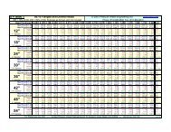
1 <strong>Flanges</strong> ver 4.26 Page 1 of 32 ASME VIII Div I Appendix 23 Code Flange Calculati<strong>on</strong>s Descripti<strong>on</strong>4 Dimensi<strong>on</strong>s:5 Fig2-4(5) fd? - Select a flange design6 22.000 A [in] - flange OD7 16.000 Bn [in] - ID, uncorroded8 1.750 t [in] - flange thickness9 0.375 rf [in] - hub corner radius10 0.750 g0f [in] - hub thickness11 0.750 g1 [in] - hub base thickness12 Gasket:13 17.750 GOD [in] - gasket OD14 16.250 GID [in] - gasket ID15 3.00 m - gasket factor16 10,000 gy - gasket factor y17 Bolting:18 20.250 varC [in] - bolt circle dia19 1.000 BoltOD [in] - bolt size20 16.0 Nbolt - number of bolts21 Operating C<strong>on</strong>diti<strong>on</strong>s:22 0.000 Corr [in] - corrosi<strong>on</strong> allowance23 100.0 P [psi] - internal operating pressure24 0.0 Pe [psi] - external operating pressure25 Material Properties:26 N<strong>on</strong>Cast CastMaterial? - Cast Or N<strong>on</strong>Cast27 20,000 Sf [psi] - allowable flange stress at DESIGN temp.28 20,000 Sfa [psi] - Allowable Flange Stress at ASSEMBLY temp.29 27,900,000 Efo [psi] -Operating Flange Modulus30 27,900,000 Efs [psi] - Seating Flange Modulus31 20,000 Sb [psi] - allowable bolt stress at DESIGN temp32 20,000 Sba [psi] - allowable bolt stress at ASSEMBLY temp33 Geometry C<strong>on</strong>straints:34 rMin = max(1/4*g1,0.188) MAX(1/4*0.75,0.188) = 0.18835 NutG [in] = PVELookup("TEMATableD5","Lookup","NutWidth",BoltOD) 1.79636 Rh [in] = PVELookup("TEMATableD5","Lookup","Rh",BoltOD) 1.37537 E [in] = PVELookup("TEMATableD5","Lookup","E",BoltOD) 1.06338 WrenchClearance = varC/2-B/2-g0-Rh ~~ TEMA Table D-5 20.25/2-16/2-0.75-1.375 = 0.00039 CkWrenchClr = WrenchClearance > 0 0 > 0 = Acceptable40 NutClearance = varC/2-B/2-g0-rf-NutG/2 ~~ TEMA Table D-541 20.25/2-16/2-0.75-0.375-1.796/2 = 0.10242 CkNutClr = NutClearance > 0 0.102 > 0 = Acceptable43 EdgeClearance = (A-E)-varC ~~ TEMA Table D-5 (22-1.063)-20.25 = 0.68744 ckEdge = EdgeClearance > 0 0.687 > 0 = Acceptable45 Calculated Dimensi<strong>on</strong>s:46 g0 = g0f-Corr 0.75-0 = 0.75047 gOne = g1-Corr 0.75-0 = 0.75048 B = Bn+2*Corr 16+2*0 = 16.00049 varR = (varC-B)/2 - gOne ~~ Gasket width in c<strong>on</strong>tact (20.25-16)/2 - 0.75 = 1.37550 varN = (GOD-GID)/2 ~~ Gasket width in c<strong>on</strong>tact (17.75-16.25)/2 = 0.75051 b0 = varN / 2 ~~ Gasket seating width 0.75 / 2 = 0.375r
<strong>Flanges</strong> ver 4.26 Page 2 of 31 varb = IF(b0>0.25,Sqrt(b0)/2,b0) ~~ Effective seating width2 IF(0.375>0.25,SQRT(0.375)/2,0.375) = 0.3063 varG = IF(b0>0.25,GOD-2*varb,(GOD-GID)/2 + GID)4 IF(0.375>0.25,17.75-2*0.306,(17.75-16.25)/2 + 16.25) = 17.1385 hub = rf ~~ Length of Hub 0.375 = 0.3756 Bolt <str<strong>on</strong>g>Loads</str<strong>on</strong>g>: (VIII App 2-5)7 Bolt size and class: 1-8 UNC 2A8 H = 0.785*varG^2*P ~~ end load 0.785*17.138^2*100 = 23,0559 He = 0.785*varG^2*Pe ~~ end load external pressure 0.785*17.138^2*0 = 010 HP = 2*varb*3.14*varG*m*P ~~ c<strong>on</strong>tact load 2*0.306*3.14*17.138*3*100 = 9,88611 HD = pi()/4 * B^2 * P ~~ end load PI()/4 * 16^2 * 100 = 20,10612 HDe = pi()/4 * B^2 * Pe ~~ end load external pressure PI()/4 * 16^2 * 0 = 013 HT = H - HD ~~ face load 23055 - 20106 = 2,94914 HTe = He - HDe ~~ face load external 0 - 0 = 015 Wm1 = H + HP ~~ bolt load 23055 + 9886 = 32,94116 Wm2 = pi()*varb*varG*gy ~~ seating load PI()*0.306*17.138*10000 = 164,84917 Am = Max(Wm1/Sb, Wm2/Sba) ~~ Bolt area required18 MAX(32941/20000, 164849/20000) = 8.24219 RootArea [sq. in] = PVELookup("BoltSizing","Lookup","Root Area",BoltOD) 0.56620 Ab = RootArea*Nbolt 0.566*16 = 9.05621 CheckExcess = Ab>=Am 9.056>=8.242 = Acceptable22 Flange <str<strong>on</strong>g>Loads</str<strong>on</strong>g>: (App 2-5)23 W [lb] = (Am + Ab)*Sba/2 ~~ seating c<strong>on</strong>diti<strong>on</strong>s (8.242 + 9.056)*20000/2 = 172,98424 HG [lb] = Wm1 - H ~~ operating c<strong>on</strong>diti<strong>on</strong>s 32941 - 23055 = 9,88625 TBoltLoad [lb] = (W+Wm1)/Nbolt (172984+32941)/16 = 12,87026 Flange Moment Arms: (Table App 2-6 - Integral flanges)27 mhD [in] = varR+0.5*gOne 1.375+0.5*0.75 = 1.75028 mhT [in] = (varR+gOne+mhG)/2 (1.375+0.75+1.556)/2 = 1.84129 mhG [in] = (varC-varG)/2 (20.25-17.138)/2 = 1.55630 Flange Moments: (App 2-6)31 MD [in-lb] = HD * mhD ~~ end pressure 20106 * 1.75 = 35,18632 MT [in-lb] = HT * mhT ~~ face pressure 2949 * 1.841 = 5,42833 MG [in-lb] = HG * mhG ~~ gasket load 9886 * 1.556 = 15,38434 Mo1e [in-lb] = HDe*(mhD-mhG)+HTe*(mhT-mhG) ~~ total operating external35 0*(1.75-1.556)+0*(1.841-1.556) = 036 Mo1 [in-lb] = Max(MD+MT+MG,Mo1e) ~~ total operating37 MAX(35186+5428+15384,0) = 55,99838 Mo2 [in-lb] = W*(varC-varG)/2 ~~ total seating 172984*(20.25-17.138)/2 = 269,19639 Graphs: App 2-7.1-6 Values of F, f, T, U, V, Y and Z40 h0 = sqrt(B*g0) SQRT(16*0.75) = 3.46441 hh0 = hub/h0 0.375/3.464 = 0.10842 g1g0 = gOne/g0 0.75/0.75 = 1.00043 F = PVELookup("F","FlangeFactor",hh0,g1g0) 0.90944 V = PVELookup("V","FlangeFactor",hh0,g1g0) 0.55045 smallF = 1 1 = 1.00046 K = A/B 22/16 = 1.37547 T = PVELookup("T","FlangeFactorK",K) 1.76548 U = PVELookup("U","FlangeFactorK",K) 6.87749 Y = PVELookup("Y","FlangeFactorK",K) 6.25850 Z = PVELookup("Z","FlangeFactorK",K) 3.24651 d = (U/V)*h0*g0^2 (6.877/0.55)*3.464*0.75^2 = 24.36052 e = F / h0 0.909 / 3.464 = 0.26253 L = (t*e + 1)/T + t^3/d (1.75*0.262 + 1)/1.765 + 1.75^3/24.36 = 1.047
<strong>Flanges</strong> ver 4.26 Page 3 of 31 Flange Seating Stress: (App 2-7,8)2 SHs = smallF*ABS(Mo2) / ( L*gOne^2 * B)3 1*ABS(269196) / ( 1.047*0.75^2 * 16) = 28,5774 CheckSHs = SHs
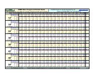
18 Flange <str<strong>on</strong>g>Loads</str<strong>on</strong>g> for FEA ver 1.12 ASME VIII div 1 App 2 Page 1 of 21920 Combined <str<strong>on</strong>g>Loads</str<strong>on</strong>g> (Operating + Seating C<strong>on</strong>diti<strong>on</strong>s)
18 Flange <str<strong>on</strong>g>Loads</str<strong>on</strong>g> for FEA ver 1.12 ASME VIII div 1 App 2 Page 1 of 21920 Operating Load Only