PV Elite Calculation Set - PVEng
PV Elite Calculation Set - PVEng
PV Elite Calculation Set - PVEng

You also want an ePaper? Increase the reach of your titles
YUMPU automatically turns print PDFs into web optimized ePapers that Google loves.
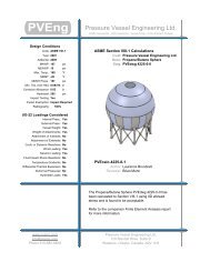
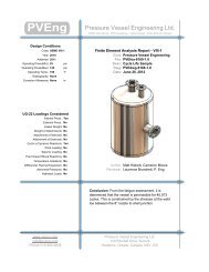
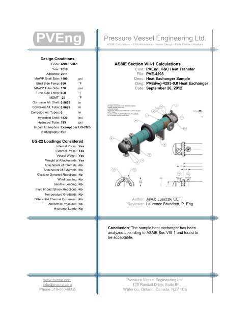
Pressure Vessel Engineering Ltd.ASME <strong>Calculation</strong>s - CRN Assistance - Vessel Design - Finite Element AnalysisDesign ConditionsCode: ASME VIII-1Year: 2010ASME Section VIII-1 <strong>Calculation</strong>sCust: <strong>PV</strong>Eng, H&C Heat TransferAddenda: 2011File: <strong>PV</strong>E-4293MAWP Shell Side: 1400 psi Desc: Heat Exchanger SampleShell Side Temp: 650 °F Dwg: <strong>PV</strong>Edwg-4293-0.0 Heat ExchangerMAWPTube Side: 150 psi Date: September 20, 2012Tube Side Temp: 650 °FMDMT: -20 °FCorrosion All. Shell: 0.0625 inCorrosion All. Tube: 0.0625 inCorrosion All. Tubes: 0inHydrotest Shell: 1820 psiHydrotest Tube: 195 psiImpact Exemption: Exempt per UG-20(f)Radiography: FullUG-22 Loadings ConsideredInternal Press.: YesExternal Press.: YesVessel Weight: YesWeight of Attachments: YesAttachment of Internals: NoAttachment of Externals: NoCyclic or Dynamic Reactions: NoWind Loading: NoSeismic Loading: NoFluid Impact Shock Reactions: NoTemperature Gradients: NoDifferential Thermal Expansion: NoAbnormal Pressures: NoHydrotest Loads: NoAuthor: Jakub Luszczki CETReviewer: Laurence Brundrett, P. Eng.Conclusion: The sample heat exchanger has beenanalyzed according to ASME Sec VIII-1 and found tobe acceptable.www.pveng.cominfo@pveng.comPhone 519-880-9808Pressure Vessel Engineering Ltd.120 Randall Drive, Suite BWaterloo, Ontario, Canada, N2V 1C6
H&C Heat Transfer Sample<strong>PV</strong>E-4293Table of ContentsCover Page 1Warnings and Errors : 2Input Echo : 3Flg Calc [Int P] : Ch. Flange 11Flg Calc [Int P] : Ch. Flange 16Internal Pressure <strong>Calculation</strong>s : 21External Pressure <strong>Calculation</strong>s : 27Element and Detail Weights : 30Nozzle Flange MAWP : 32Center of Gravity <strong>Calculation</strong> : 33Horizontal Vessel Analysis (Ope.) 34Horizontal Vessel Analysis (Test) 42Nozzle Calcs. : T1/T2 50Nozzle Calcs. : S2 57Nozzle Calcs. : S1 64Nozzle Calcs. : S3 71Nozzle Calcs. : T3 & T4 75Nozzle Schedule : 78Nozzle Summary : 79MDMT Summary : 80ASME TS Calc : 81Vessel Design Summary : 95
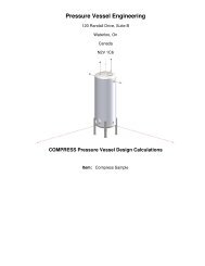
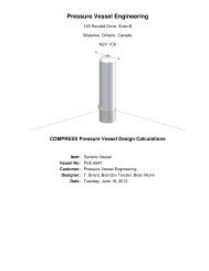
Cover PageH&C Heat Transfer Sample<strong>PV</strong>E-4293DESIGN CALCULATIONIn Accordance with ASME Section VIII Division 1ASME Code Version: 2010 Edition, 2011a AddendaAnalysis Performed by : PRESSURE VESSEL ENGINEERINGJob File : \\<strong>PV</strong>ESERVER\JOBS\4000-4999\4200-4299\4293 H&C HEDate of Analysis : Sep 18,2012<strong>PV</strong> <strong>Elite</strong> 2012, January 2012
H&C Heat Transfer Sample<strong>PV</strong>E-4293<strong>PV</strong> <strong>Elite</strong> 2012 Licensee: PRESSURE VESSEL ENGINEERINGFileName : <strong>PV</strong>Ecalc-4293-0.0 ------------------------------ Page 2 of 96Warnings and Errors : Step: 0 5:58p Sep 18,2012Class From To : Basic Element Checks.==========================================================================Class From To: Check of Additional Element Data==========================================================================There were no geometry errors or warnings.<strong>PV</strong><strong>Elite</strong> is atrademarkof IntergraphCADWorx&AnalysisSolutions, Inc. 2012
H&C Heat Transfer Sample<strong>PV</strong>E-4293<strong>PV</strong> <strong>Elite</strong> 2012 Licensee: PRESSURE VESSEL ENGINEERINGFileName : <strong>PV</strong>Ecalc-4293-0.0 ------------------------------ Page 3 of 96Input Echo : Step: 1 5:58p Sep 18,2012<strong>PV</strong> <strong>Elite</strong> Vessel Analysis Program: Input DataH&C Heat Transfer Sample<strong>PV</strong>E-4293ExchangerDesign Pressures andTemperaturesShell Side Design Pressure1400.0 psigChannel Side Design Pressure150.00 psigShell Side Design Temperature 650 FChannel Side Design Temperature 650 FType of Hydrotest UG99-b Note [34]Hydrotest Position HorizontalProjection of Nozzle from Vessel Top0.0000 in.Projection of Nozzle from Vessel Bottom0.0000 in.Minimum Design Metal Temperature -20 FType of ConstructionWeldedSpecial Service NoneDegree of Radiography RT 1Miscellaneous Weight Percent 0.0Use Higher Longitudinal Stresses (Flag)YSelect t for Internal Pressure (Flag) NSelect t for External Pressure (Flag) NSelect t for Axial Stress (Flag) NSelect Location for Stiff. Rings (Flag)NConsider Vortex Shedding NPerform a Corroded Hydrotest NIs this a Heat Exchanger YesUser Defined Hydro. Press. (Used if > 0)0.0000 psigUser defined MAWP0.0000 psigUser defined MAPnc0.0000 psigLoad Case 1 NP+EW+WI+FW+BWLoad Case 2 NP+EW+EE+FS+BSLoad Case 3 NP+OW+WI+FW+BWLoad Case 4 NP+OW+EQ+FS+BSLoad Case 5 NP+HW+HILoad Case 6 NP+HW+HELoad Case 7 IP+OW+WI+FW+BWLoad Case 8 IP+OW+EQ+FS+BSLoad Case 9 EP+OW+WI+FW+BWLoad Case 10 EP+OW+EQ+FS+BSLoad Case 11 HP+HW+HILoad Case 12 HP+HW+HELoad Case 13 IP+WE+EWLoad Case 14 IP+WF+CWLoad Case 15 IP+VO+OWLoad Case 16 IP+VE+EWLoad Case 17 NP+VO+OWLoad Case 18 FS+BS+IP+OWLoad Case 19 FS+BS+EP+OWWind Design Code No Wind LoadsSeismic Design Code No Seismic
H&C Heat Transfer Sample<strong>PV</strong>E-4293<strong>PV</strong> <strong>Elite</strong> 2012 Licensee: PRESSURE VESSEL ENGINEERINGFileName : <strong>PV</strong>Ecalc-4293-0.0 ------------------------------ Page 4 of 96Input Echo : Step: 1 5:58p Sep 18,2012Design Nozzle for Des. Press. + St. Head YConsider MAP New and Cold in Noz. Design NConsider External Loads for Nozzle Des.YUse ASME VIII-1 Appendix 1-9 NMaterial Database Year 2009ConfigurationDirectives:Do not use Nozzle MDMT Interpretation VIII-1 01-37 NoUse Table G instead of exact equation for "A" YesShell Head Joints are Tapered YesCompute "K" in corroded condition YesUse Code Case 2286 NoUse the MAWP to compute the MDMT YesUsing Metric Material Databases, ASME II D NoComplete Listing of Vessel Elements and Details:Element From Node 10Element To Node 20Element Type EllipticalDescription Left HeadDistance "FROM" to "TO"0.08330 ft.Element Outside Diameter18.500 in.Element Thickness0.1680 in.Internal Corrosion Allowance0.06250 in.Nominal Thickness0.1875 in.External Corrosion Allowance0.0000 in.Design Internal Pressure150.00 psigDesign Temperature Internal Pressure 650 FDesign External Pressure0.0000 psigDesign Temperature External Pressure 650 FEffective Diameter Multiplier 1.2Material Name SA-516 70Allowable Stress, Ambient20000. psiAllowable Stress, Operating18800. psiAllowable Stress, Hydrotest26000. psiMaterial Density0.2830 lb./in³P Number Thickness1.2500 in.Yield Stress, Operating28200. psiUCS-66 Chart Curve Designation BExternal Pressure Chart Name CS-2UNS NumberK02700Product Form PlateEfficiency, Longitudinal Seam 1.0Efficiency, Circumferential Seam 1.0Elliptical Head Factor 2.0Element From Node 10Detail TypeLiquidDetail ID HEADDist. from "FROM" Node / Offset dist0.1600 ft.Height/Length of Liquid1.5137 ft.Liquid Density62.400 lb./ft³
H&C Heat Transfer Sample<strong>PV</strong>E-4293<strong>PV</strong> <strong>Elite</strong> 2012 Licensee: PRESSURE VESSEL ENGINEERINGFileName : <strong>PV</strong>Ecalc-4293-0.0 ------------------------------ Page 5 of 96Input Echo : Step: 1 5:58p Sep 18,2012--------------------------------------------------------------------Element From Node 20Element To Node 30Element Type CylinderDescription Left ChannelDistance "FROM" to "TO"0.7290 ft.Element Outside Diameter18.500 in.Element Thickness0.1875 in.Internal Corrosion Allowance0.06250 in.Nominal Thickness0.1875 in.External Corrosion Allowance0.0000 in.Design Internal Pressure150.00 psigDesign Temperature Internal Pressure 650 FDesign External Pressure0.0000 psigDesign Temperature External Pressure 650 FEffective Diameter Multiplier 1.2Material Name SA-516 70Efficiency, Longitudinal Seam 1.0Efficiency, Circumferential Seam 1.0Element From Node 20Detail TypeLiquidDetail IDCHANNELDist. from "FROM" Node / Offset dist0.8300 ft.Height/Length of Liquid1.5104 ft.Liquid Density62.400 lb./ft³Element From Node 20Detail TypeNozzleDetail ID T1/T2Dist. from "FROM" Node / Offset dist0.3600 ft.Nozzle Diameter 4.0 in.Nozzle Schedule 40Nozzle Class 300Layout Angle 110.57Blind Flange (Y/N) NWeight of Nozzle ( Used if > 0 )0.0000 lb.Grade of Attached Flange GR 1.1Nozzle Matl SA-106 B--------------------------------------------------------------------Element From Node 30Element To Node 40Element Type FlangeDescription Channel FlangeDistance "FROM" to "TO"0.2396 ft.Flange Inside Diameter18.125 in.Element Thickness1.7500 in.Internal Corrosion Allowance0.06250 in.Nominal Thickness1.7500 in.External Corrosion Allowance0.0000 in.Design Internal Pressure150.00 psigDesign Temperature Internal Pressure 650 FDesign External Pressure0.0000 psigDesign Temperature External Pressure 650 F
H&C Heat Transfer Sample<strong>PV</strong>E-4293<strong>PV</strong> <strong>Elite</strong> 2012 Licensee: PRESSURE VESSEL ENGINEERINGFileName : <strong>PV</strong>Ecalc-4293-0.0 ------------------------------ Page 6 of 96Input Echo : Step: 1 5:58p Sep 18,2012Effective Diameter Multiplier 1.2Material NameSA-105Allowable Stress, Ambient20000. psiAllowable Stress, Operating17800. psiAllowable Stress, Hydrotest26000. psiMaterial Density0.2830 lb./in³P Number Thickness1.2500 in.Yield Stress, Operating26700. psiUCS-66 Chart Curve Designation BExternal Pressure Chart Name CS-2UNS NumberK03504Product Form ForgingsPerform Flange Stress <strong>Calculation</strong> (Y/N)YWeight of ANSI B16.5/B16.47 Flange0.0000 lb.Class of ANSI B16.5/B16.47 FlangeGrade of ANSI B16.5/B16.47 Flange--------------------------------------------------------------------Element From Node 40Element To Node 50Element Type CylinderDescription ShellDistance "FROM" to "TO"7.6670 ft.Element Outside Diameter18.500 in.Element Thickness0.7500 in.Internal Corrosion Allowance0.06250 in.Nominal Thickness0.7500 in.External Corrosion Allowance0.0000 in.Design Internal Pressure1400.0 psigDesign Temperature Internal Pressure 650 FDesign External Pressure15.000 psigDesign Temperature External Pressure 650 FEffective Diameter Multiplier 1.2Material Name SA-516 70Allowable Stress, Ambient20000. psiAllowable Stress, Operating18800. psiAllowable Stress, Hydrotest26000. psiMaterial Density0.2830 lb./in³P Number Thickness1.2500 in.Yield Stress, Operating28200. psiUCS-66 Chart Curve Designation BExternal Pressure Chart Name CS-2UNS NumberK02700Product Form PlateEfficiency, Longitudinal Seam 1.0Efficiency, Circumferential Seam 1.0Element From Node 40Detail TypeSaddleDetail IDLft SdlDist. from "FROM" Node / Offset dist1.5989 ft.Width of Saddle4.0000 in.Height of Saddle at Bottom25.000 in.Saddle Contact Angle 120.0Height of Composite Ring Stiffener0.0000 in.Width of Wear Plate5.0000 in.
H&C Heat Transfer Sample<strong>PV</strong>E-4293<strong>PV</strong> <strong>Elite</strong> 2012 Licensee: PRESSURE VESSEL ENGINEERINGFileName : <strong>PV</strong>Ecalc-4293-0.0 ------------------------------ Page 7 of 96Input Echo : Step: 1 5:58p Sep 18,2012Thickness of Wear Plate0.2500 in.Contact Angle, Wear Plate (degrees) 132.0Element From Node 40Detail TypeSaddleDetail IDRgt SdlDist. from "FROM" Node / Offset dist6.4000 ft.Width of Saddle4.0000 in.Height of Saddle at Bottom25.000 in.Saddle Contact Angle 120.0Height of Composite Ring Stiffener0.0000 in.Width of Wear Plate5.0000 in.Thickness of Wear Plate0.2500 in.Contact Angle, Wear Plate (degrees) 132.0Element From Node 40Detail TypeLiquidDetail ID SHELLDist. from "FROM" Node / Offset dist0.0000 ft.Height/Length of Liquid1.4427 ft.Liquid Density62.400 lb./ft³Element From Node 40Detail TypeNozzleDetail ID S2Dist. from "FROM" Node / Offset dist0.5000 ft.Nozzle Diameter 3.0 in.Nozzle Schedule XXSNozzle Class 900Layout Angle 270.0Blind Flange (Y/N) NWeight of Nozzle ( Used if > 0 )0.0000 lb.Grade of Attached Flange GR 1.1Nozzle Matl SA-106 BElement From Node 40Detail TypeNozzleDetail ID S1Dist. from "FROM" Node / Offset dist7.2900 ft.Nozzle Diameter 6.0 in.Nozzle Schedule XXSNozzle Class 900Layout Angle 270.0Blind Flange (Y/N) NWeight of Nozzle ( Used if > 0 )0.0000 lb.Grade of Attached Flange GR 1.1Nozzle Matl SA-106 BElement From Node 40Detail TypeNozzleDetail ID S3Dist. from "FROM" Node / Offset dist0.5000 ft.Nozzle Diameter 2.0 in.Nozzle Schedule XXSNozzle Class 900Layout Angle 90.0Blind Flange (Y/N) N
H&C Heat Transfer Sample<strong>PV</strong>E-4293<strong>PV</strong> <strong>Elite</strong> 2012 Licensee: PRESSURE VESSEL ENGINEERINGFileName : <strong>PV</strong>Ecalc-4293-0.0 ------------------------------ Page 8 of 96Input Echo : Step: 1 5:58p Sep 18,2012Weight of Nozzle ( Used if > 0 )0.0000 lb.Grade of Attached Flange GR 1.1Nozzle Matl SA-106 B--------------------------------------------------------------------Element From Node 50Element To Node 60Element Type FlangeDescription Channel FlangeDistance "FROM" to "TO"0.2396 ft.Flange Inside Diameter18.125 in.Element Thickness1.7500 in.Internal Corrosion Allowance0.06250 in.Nominal Thickness1.7500 in.External Corrosion Allowance0.0000 in.Design Internal Pressure150.00 psigDesign Temperature Internal Pressure 650 FDesign External Pressure0.0000 psigDesign Temperature External Pressure 650 FEffective Diameter Multiplier 1.2Material NameSA-105Allowable Stress, Ambient20000. psiAllowable Stress, Operating17800. psiAllowable Stress, Hydrotest26000. psiMaterial Density0.2830 lb./in³P Number Thickness1.2500 in.Yield Stress, Operating26700. psiUCS-66 Chart Curve Designation BExternal Pressure Chart Name CS-2UNS NumberK03504Product Form ForgingsPerform Flange Stress <strong>Calculation</strong> (Y/N)YWeight of ANSI B16.5/B16.47 Flange0.0000 lb.Class of ANSI B16.5/B16.47 FlangeGrade of ANSI B16.5/B16.47 Flange--------------------------------------------------------------------Element From Node 60Element To Node 70Element Type CylinderDescriptionChannelDistance "FROM" to "TO"0.7290 ft.Element Outside Diameter18.500 in.Element Thickness0.1875 in.Internal Corrosion Allowance0.06250 in.Nominal Thickness0.1875 in.External Corrosion Allowance0.0000 in.Design Internal Pressure150.00 psigDesign Temperature Internal Pressure 650 FDesign External Pressure0.0000 psigDesign Temperature External Pressure 650 FEffective Diameter Multiplier 1.2Material Name SA-516 70Allowable Stress, Ambient20000. psiAllowable Stress, Operating18800. psi
H&C Heat Transfer Sample<strong>PV</strong>E-4293<strong>PV</strong> <strong>Elite</strong> 2012 Licensee: PRESSURE VESSEL ENGINEERINGFileName : <strong>PV</strong>Ecalc-4293-0.0 ------------------------------ Page 9 of 96Input Echo : Step: 1 5:58p Sep 18,2012Allowable Stress, Hydrotest26000. psiMaterial Density0.2830 lb./in³P Number Thickness1.2500 in.Yield Stress, Operating28200. psiUCS-66 Chart Curve Designation BExternal Pressure Chart Name CS-2UNS NumberK02700Product Form PlateEfficiency, Longitudinal Seam 1.0Efficiency, Circumferential Seam 1.0Element From Node 60Detail TypeLiquidDetail IDCHANNELDist. from "FROM" Node / Offset dist0.0000 ft.Height/Length of Liquid1.5104 ft.Liquid Density62.400 lb./ft³Element From Node 60Detail TypeNozzleDetail IDT3 & T4Dist. from "FROM" Node / Offset dist0.5000 ft.Nozzle Diameter 1.0 in.Nozzle Schedule 80Nozzle Class 300Layout Angle 90.0Blind Flange (Y/N) NWeight of Nozzle ( Used if > 0 )0.0000 lb.Grade of Attached Flange GR 1.1Nozzle Matl SA-106 B--------------------------------------------------------------------Element From Node 70Element To Node 80Element Type EllipticalDescription Right HeadDistance "FROM" to "TO"0.08330 ft.Element Outside Diameter18.500 in.Element Thickness0.1680 in.Internal Corrosion Allowance0.06250 in.Nominal Thickness0.1875 in.External Corrosion Allowance0.0000 in.Design Internal Pressure150.00 psigDesign Temperature Internal Pressure 650 FDesign External Pressure0.0000 psigDesign Temperature External Pressure 650 FEffective Diameter Multiplier 1.2Material Name SA-516 70Efficiency, Longitudinal Seam 1.0Efficiency, Circumferential Seam 1.0Elliptical Head Factor 2.0Element From Node 70Detail TypeLiquidDetail ID HEADDist. from "FROM" Node / Offset dist0.0000 ft.
H&C Heat Transfer Sample<strong>PV</strong>E-4293<strong>PV</strong> <strong>Elite</strong> 2012 Licensee: PRESSURE VESSEL ENGINEERINGFileName : <strong>PV</strong>Ecalc-4293-0.0 ------------------------------ Page 10 of 96Input Echo : Step: 1 5:58p Sep 18,2012Height/Length of LiquidLiquid Density1.5137 ft.62.400 lb./ft³<strong>PV</strong><strong>Elite</strong> is atrademarkof IntergraphCADWorx&AnalysisSolutions, Inc. 2012
H&C Heat Transfer Sample<strong>PV</strong>E-4293<strong>PV</strong> <strong>Elite</strong> 2012 Licensee: PRESSURE VESSEL ENGINEERINGFileName : <strong>PV</strong>Ecalc-4293-0.0 ------------------------------ Page 11 of 96Flg Calc [Int P] : Ch. Flange Flng: 3 5:58p Sep 18,2012Flange Input Data Values Description: Ch. Flange :Channel FlangeDescription of Flange Geometry (Type) Integral Weld NeckDesign Pressure P 150.00 psigDesign Temperature650 FInternal Corrosion Allowance ci 0.0625 in.External Corrosion Allowance ce 0.0000 in.Use Corrosion Allowance in Thickness Calcs. NoFlange Inside Diameter B 18.125 in.Flange Outside Diameter A 23.500 in.Flange Thickness t 1.7500 in.Thickness of Hub at Small End go 0.1875 in.Thickness of Hub at Large End g1 0.5625 in.Length of Hub h 1.1250 in.Flange Material SA-105Flange Material UNS number K03504Flange Allowable Stress At Temperature Sfo 17800.00 psiFlange Allowable Stress At Ambient Sfa 20000.00 psiBolt Material SA-193 B7Bolt Allowable Stress At Temperature Sb 25000.00 psiBolt Allowable Stress At Ambient Sa 25000.00 psiDiameter of Bolt Circle C 21.750 in.Nominal Bolt Diameter dB 0.6250 in.Type of ThreadsUNC Thread SeriesNumber of Bolts 16Flange Face Outside Diameter Fod 19.750 in.Flange Face Inside Diameter Fid 18.125 in.Flange Facing Sketch1, Code Sketch 1aGasket Outside Diameter Go 19.125 in.Gasket Inside Diameter Gi 18.125 in.Gasket Factor m 2.5000Gasket Design Seating Stress y 2900.00 psiColumn for Gasket Seating2, Code Column IIGasket Thickness tg 0.1250 in.Length of Partition Gasket lp 18.1250 in.Width of Partition Gasket tp 0.3130 in.Partition Gasket Factor mPart 2.5000Partition Gasket Design Seating Stress yPart2900.00 psiASME Code, Section VIII, Division 1, 2010, 2011aHub Small End Required Thickness due to Internal Pressure:= (P*(D/2+Ca))/(S*E-0.6*P) per UG-27 (c)(1)= (150.00*(18.1250/2+0.0625))/(17800.00*1.00-0.6*150.00)+Ca= 0.1398 in.
H&C Heat Transfer Sample<strong>PV</strong>E-4293<strong>PV</strong> <strong>Elite</strong> 2012 Licensee: PRESSURE VESSEL ENGINEERINGFileName : <strong>PV</strong>Ecalc-4293-0.0 ------------------------------ Page 12 of 96Flg Calc [Int P] : Ch. Flange Flng: 3 5:58p Sep 18,2012Hub Small End Hub MAWP:= (S*E*t)/(R+0.6*t) per UG-27 (c)(1)= (17800.00 * 1.00 * 0.1250 )/(9.1250 + 0.6 * 0.1250 )= 241.848 psigCorroded Flange ID, Bcor = B+2*Fcor 18.250 in.Corroded Large Hub, g1Cor = g1-ci 0.500 in.Corroded Small Hub, g0Cor = go-ci 0.125 in.Code R Dimension, R = ((C-Bcor)/2)-g1cor 1.250 in.Gasket Contact Width, N = (Go - Gi) / 2 0.500 in.Basic Gasket Width, bo = N / 2 0.250 in.Effective Gasket Width, b = bo 0.250 in.Gasket Reaction Diameter, G = (Go + Gi) / 2 18.625 in.Basic Flange and Bolt Loads:Hydrostatic End Load due to Pressure [H]:= 0.785 * G² * Peq= 0.785 * 18.6250² * 150.000= 40867.090 lb.Contact Load on Gasket Surfaces [Hp]:= 2 * b * Pi * G * m * P + 2 * lp * bPart * mPart * P= 2 * 0.2500 * 3.1416 * 18.6250 * 2.5000 * 150.00+ 2.0 * 18.1250 * 0.1565 * 2.5000 * 150.0000= 13098.453 lb.Hydrostatic End Load at Flange ID [Hd]:= Pi * Bcor² * P / 4= 3.1416 * 18.2500² *150.0000/4= 39238.004 lb.Pressure Force on Flange Face [Ht]:= H - Hd= 40867 - 39238= 1629.086 lb.Operating Bolt Load [Wm1]:= max( H + Hp + H'p, 0 )= max( 40867 + 13098 + 0 , 0 )= 53965.543 lb.Gasket Seating Bolt Load [Wm2]:= y * b * Pi * G + yPart * bPart * lp= 2900.00*0.2500*3.141*18.625+2900.00*0.1565*18.12= 50647.352 lb.Required Bolt Area [Am]:= Maximum of Wm1/Sb, Wm2/Sa= Maximum of 53965/25000 , 50647/25000= 2.159 in²ASME Maximum Circumferential Spacing between Bolts per App. 2eq. (3) [Bsmax]:= 2a + 6t/(m + 0.5)= 2 * 0.625 + 6 * 1.750/(2.50 + 0.5)= 4.750 in.Actual Circumferential Bolt Spacing [Bs]:= C * sin( pi / n ) )= 21.750 * sin( 3.142/16 )= 4.243 in.
H&C Heat Transfer Sample<strong>PV</strong>E-4293<strong>PV</strong> <strong>Elite</strong> 2012 Licensee: PRESSURE VESSEL ENGINEERINGFileName : <strong>PV</strong>Ecalc-4293-0.0 ------------------------------ Page 13 of 96Flg Calc [Int P] : Ch. Flange Flng: 3 5:58p Sep 18,2012ASME Moment Multiplier for Bolt Spacing per App. 2eq. (7) [Bsc]:= max( sqrt( Bs/( 2a + t )), 1 )= max( sqrt( 4.243/( 2 * 0.625 + 1.750 )), 1 )= 1.1893Bolting InformationforUNCThreadSeries(Non Mandatory):-----------------------------------------------------------------------------Minimum Actual Maximum-----------------------------------------------------------------------------Bolt Area, in² 2.159 3.232Radial distance bet. hub and bolts 0.938 1.250Radial distance bet. bolts and the edge 0.750 0.875Circumferential spacing between bolts 1.500 4.243 4.750-----------------------------------------------------------------------------Min. Gasket Contact Width (Brownell Young) [Not an ASME Calc] [Nmin]:= Ab * Sa/( y * Pi * (Go + Gi) )= 3.232 * 25000.00/(2900.00 * 3.14 * (19.125 + 18.12 ) )= 0.238 in.Flange Design Bolt Load, Gasket Seating [W]:= Sa * ( Am + Ab ) / 2= 25000.00 * ( 2.1586 + 3.2320 )/2= 67382.77 lb.Gasket Load for the Operating Condition [HG]:= Wm1 - H= 53965 - 40867= 13098.45 lb.Moment Arm <strong>Calculation</strong>s:Distance to Gasket Load Reaction [hg]:= (C - G ) / 2= ( 21.7500 - 18.6250 )/2= 1.5625 in.Distance to Face Pressure Reaction [ht]:= ( R + g1 + hg ) / 2= ( 1.2500 + 0.5000 + 1.5625 )/2= 1.6562 in.Distance to End Pressure Reaction [hd]:= R + ( g1 / 2 )= 1.2500 + ( 0.5000/2.0 )= 1.5000 in.Summary of Moments for Internal Pressure:Loading Force Distance Bolt Corr MomentEnd Pressure, Md 39238. 1.5000 1.1893 5833. ft.lb.Face Pressure, Mt 1629. 1.6562 1.1893 267. ft.lb.Gasket Load, Mg 13098. 1.5625 1.1893 2028. ft.lb.Gasket Seating, Matm 67383. 1.5625 1.1893 10435. ft.lb.Total Moment for Operation, Mop 8129. ft.lb.Total Moment for Gasket seating, Matm 10435. ft.lb.Effective Hub Length, ho = sqrt(Bcor*goCor)1.510 in.Hub Ratio, h/h0 = HL / H0 0.745Thickness Ratio, g1/g0 = (g1Cor/goCor) 4.000
H&C Heat Transfer Sample<strong>PV</strong>E-4293<strong>PV</strong> <strong>Elite</strong> 2012 Licensee: PRESSURE VESSEL ENGINEERINGFileName : <strong>PV</strong>Ecalc-4293-0.0 ------------------------------ Page 14 of 96Flg Calc [Int P] : Ch. Flange Flng: 3 5:58p Sep 18,2012Flange Factors for Integral Flange:Factor F per 2-7.2 0.736Factor V per 2-7.3 0.081Factor f per 2-7.6 2.930Factors from Figure 2-7.1 K = 1.288T = 1.803 U = 8.595Y = 7.822 Z = 4.039d = 2.513 in.³ e = 0.4875 in.^-1Stress Factors ALPHA = 1.853BETA = 2.138 GAMMA = 1.028DELTA = 2.133 Lamda = 3.161Longitudinal Hub Stress, Operating [SHo]:= ( f * Mop / Bcor ) / ( L * g1² )= (2.9303*97547/18.2500)/(3.1608*0.5000²)= 19821.01 psiLongitudinal Hub Stress, Seating [SHa]:= ( f * Matm / Bcor ) / ( L * g1² )= (2.9303*125214/18.2500)/(3.1608*0.5000²)= 25442.91 psiRadial Flange Stress, Operating [SRo]:= ( Beta * Mop / Bcor ) / ( L * t² )= (2.1376*97547/18.2500)/(3.1608*1.7500²)= 1180.33 psiRadial Flange Stress, Seating [SRa]:= ( Beta * Matm/Bcor ) / ( L * t² )= (2.1376*125214/18.2500)/(3.1608*1.7500²)= 1515.11 psiTangential Flange Stress, Operating [STo]:= ( Y * Mo / (t² * Bcor) ) - Z * SRo= (7.8217*97547/(1.7500²*18.2500))-4.0391*1180= 8883.92 psiTangential Flange Stress, Seating [STa]:= ( y * Matm / (t² * Bcor) ) - Z * SRa= (7.8217*125214/(1.7500²*18.2500))-4.0391*1515= 11403.70 psiAverage Flange Stress, Operating [SAo]:= ( SHo + max( SRo, STo ) ) / 2= (19821+max(1180,8883))/2= 14352.46 psiAverage Flange Stress, Seating [SAa]:= ( SHa + max( SRa, STa ) ) / 2= (25442+max(1515,11403))/2= 18423.30 psiBolt Stress, Operating [BSo]:= ( Wm1 / Ab )= (53965/3.2320)= 16697.26 psiBolt Stress, Seating [BSa]:= ( Wm2 / Ab )= (50647/3.2320)= 15670.59 psi
H&C Heat Transfer Sample<strong>PV</strong>E-4293<strong>PV</strong> <strong>Elite</strong> 2012 Licensee: PRESSURE VESSEL ENGINEERINGFileName : <strong>PV</strong>Ecalc-4293-0.0 ------------------------------ Page 15 of 96Flg Calc [Int P] : Ch. Flange Flng: 3 5:58p Sep 18,2012Stress Computation Results: Operating Gasket SeatingActual Allowed Actual AllowedLongitudinal Hub 19821. 26700. 25443. 30000. psiRadial Flange 1180. 17800. 1515. 20000. psiTangential Flange 8884. 17800. 11404. 20000. psiMaximum Average 14352. 17800. 18423. 20000. psiBolting 16697. 25000. 15671. 25000. psiMinimum Required Flange Thickness 1.684 in.Estimated M.A.W.P. ( Operating ) 186.0 psigEstimated Finished Weight of Flange at given Thk. 94.0 lbmEstimated Unfinished Weight of Forging at given Thk 143.0 lbmFlange Rigidity Based on Required Thickness [ASME]:Flange Rigidity Index, Seating (rotation check) per APP. 2[Js]:= 52.14 * Ma / Bsc * Cnv_fac * V / ( Lambda * Eamb * go^(2) * ho * Ki )= 52.14 * 10434.6/1.2026 * 12.000 * 0.081/( 2.908 * 29400000 *0.125^(2) * 1.510 * 0.300 )= 0.724 (should be
H&C Heat Transfer Sample<strong>PV</strong>E-4293<strong>PV</strong> <strong>Elite</strong> 2012 Licensee: PRESSURE VESSEL ENGINEERINGFileName : <strong>PV</strong>Ecalc-4293-0.0 ------------------------------ Page 16 of 96Flg Calc [Int P] : Ch. Flange Flng: 4 5:58p Sep 18,2012Flange Input Data Values Description: Ch. Flange :Channel FlangeDescription of Flange Geometry (Type) Integral Weld NeckDesign Pressure P 150.00 psigDesign Temperature650 FInternal Corrosion Allowance ci 0.0625 in.External Corrosion Allowance ce 0.0000 in.Use Corrosion Allowance in Thickness Calcs. NoFlange Inside Diameter B 18.125 in.Flange Outside Diameter A 23.500 in.Flange Thickness t 1.7500 in.Thickness of Hub at Small End go 0.1875 in.Thickness of Hub at Large End g1 0.5625 in.Length of Hub h 1.1250 in.Flange Material SA-105Flange Material UNS number K03504Flange Allowable Stress At Temperature Sfo 17800.00 psiFlange Allowable Stress At Ambient Sfa 20000.00 psiBolt Material SA-193 B7Bolt Allowable Stress At Temperature Sb 25000.00 psiBolt Allowable Stress At Ambient Sa 25000.00 psiDiameter of Bolt Circle C 21.750 in.Nominal Bolt Diameter dB 0.6250 in.Type of ThreadsUNC Thread SeriesNumber of Bolts 16Flange Face Outside Diameter Fod 19.750 in.Flange Face Inside Diameter Fid 18.125 in.Flange Facing Sketch1, Code Sketch 1aGasket Outside Diameter Go 19.125 in.Gasket Inside Diameter Gi 18.125 in.Gasket Factor m 2.5000Gasket Design Seating Stress y 2900.00 psiColumn for Gasket Seating2, Code Column IIGasket Thickness tg 0.1250 in.Length of Partition Gasket lp 18.1250 in.Width of Partition Gasket tp 0.3130 in.Partition Gasket Factor mPart 2.5000Partition Gasket Design Seating Stress yPart2900.00 psiASME Code, Section VIII, Division 1, 2010, 2011aHub Small End Required Thickness due to Internal Pressure:= (P*(D/2+Ca))/(S*E-0.6*P) per UG-27 (c)(1)= (150.00*(18.1250/2+0.0625))/(17800.00*1.00-0.6*150.00)+Ca= 0.1398 in.
H&C Heat Transfer Sample<strong>PV</strong>E-4293<strong>PV</strong> <strong>Elite</strong> 2012 Licensee: PRESSURE VESSEL ENGINEERINGFileName : <strong>PV</strong>Ecalc-4293-0.0 ------------------------------ Page 17 of 96Flg Calc [Int P] : Ch. Flange Flng: 4 5:58p Sep 18,2012Hub Small End Hub MAWP:= (S*E*t)/(R+0.6*t) per UG-27 (c)(1)= (17800.00 * 1.00 * 0.1250 )/(9.1250 + 0.6 * 0.1250 )= 241.848 psigCorroded Flange ID, Bcor = B+2*Fcor 18.250 in.Corroded Large Hub, g1Cor = g1-ci 0.500 in.Corroded Small Hub, g0Cor = go-ci 0.125 in.Code R Dimension, R = ((C-Bcor)/2)-g1cor 1.250 in.Gasket Contact Width, N = (Go - Gi) / 2 0.500 in.Basic Gasket Width, bo = N / 2 0.250 in.Effective Gasket Width, b = bo 0.250 in.Gasket Reaction Diameter, G = (Go + Gi) / 2 18.625 in.Basic Flange and Bolt Loads:Hydrostatic End Load due to Pressure [H]:= 0.785 * G² * Peq= 0.785 * 18.6250² * 150.000= 40867.090 lb.Contact Load on Gasket Surfaces [Hp]:= 2 * b * Pi * G * m * P + 2 * lp * bPart * mPart * P= 2 * 0.2500 * 3.1416 * 18.6250 * 2.5000 * 150.00+ 2.0 * 18.1250 * 0.1565 * 2.5000 * 150.0000= 13098.453 lb.Hydrostatic End Load at Flange ID [Hd]:= Pi * Bcor² * P / 4= 3.1416 * 18.2500² *150.0000/4= 39238.004 lb.Pressure Force on Flange Face [Ht]:= H - Hd= 40867 - 39238= 1629.086 lb.Operating Bolt Load [Wm1]:= max( H + Hp + H'p, 0 )= max( 40867 + 13098 + 0 , 0 )= 53965.543 lb.Gasket Seating Bolt Load [Wm2]:= y * b * Pi * G + yPart * bPart * lp= 2900.00*0.2500*3.141*18.625+2900.00*0.1565*18.12= 50647.352 lb.Required Bolt Area [Am]:= Maximum of Wm1/Sb, Wm2/Sa= Maximum of 53965/25000 , 50647/25000= 2.159 in²ASME Maximum Circumferential Spacing between Bolts per App. 2eq. (3) [Bsmax]:= 2a + 6t/(m + 0.5)= 2 * 0.625 + 6 * 1.750/(2.50 + 0.5)= 4.750 in.Actual Circumferential Bolt Spacing [Bs]:= C * sin( pi / n ) )= 21.750 * sin( 3.142/16 )= 4.243 in.
H&C Heat Transfer Sample<strong>PV</strong>E-4293<strong>PV</strong> <strong>Elite</strong> 2012 Licensee: PRESSURE VESSEL ENGINEERINGFileName : <strong>PV</strong>Ecalc-4293-0.0 ------------------------------ Page 18 of 96Flg Calc [Int P] : Ch. Flange Flng: 4 5:58p Sep 18,2012ASME Moment Multiplier for Bolt Spacing per App. 2eq. (7) [Bsc]:= max( sqrt( Bs/( 2a + t )), 1 )= max( sqrt( 4.243/( 2 * 0.625 + 1.750 )), 1 )= 1.1893Bolting InformationforUNCThreadSeries(Non Mandatory):-----------------------------------------------------------------------------Minimum Actual Maximum-----------------------------------------------------------------------------Bolt Area, in² 2.159 3.232Radial distance bet. hub and bolts 0.938 1.250Radial distance bet. bolts and the edge 0.750 0.875Circumferential spacing between bolts 1.500 4.243 4.750-----------------------------------------------------------------------------Min. Gasket Contact Width (Brownell Young) [Not an ASME Calc] [Nmin]:= Ab * Sa/( y * Pi * (Go + Gi) )= 3.232 * 25000.00/(2900.00 * 3.14 * (19.125 + 18.12 ) )= 0.238 in.Flange Design Bolt Load, Gasket Seating [W]:= Sa * ( Am + Ab ) / 2= 25000.00 * ( 2.1586 + 3.2320 )/2= 67382.77 lb.Gasket Load for the Operating Condition [HG]:= Wm1 - H= 53965 - 40867= 13098.45 lb.Moment Arm <strong>Calculation</strong>s:Distance to Gasket Load Reaction [hg]:= (C - G ) / 2= ( 21.7500 - 18.6250 )/2= 1.5625 in.Distance to Face Pressure Reaction [ht]:= ( R + g1 + hg ) / 2= ( 1.2500 + 0.5000 + 1.5625 )/2= 1.6562 in.Distance to End Pressure Reaction [hd]:= R + ( g1 / 2 )= 1.2500 + ( 0.5000/2.0 )= 1.5000 in.Summary of Moments for Internal Pressure:Loading Force Distance Bolt Corr MomentEnd Pressure, Md 39238. 1.5000 1.1893 5833. ft.lb.Face Pressure, Mt 1629. 1.6562 1.1893 267. ft.lb.Gasket Load, Mg 13098. 1.5625 1.1893 2028. ft.lb.Gasket Seating, Matm 67383. 1.5625 1.1893 10435. ft.lb.Total Moment for Operation, Mop 8129. ft.lb.Total Moment for Gasket seating, Matm 10435. ft.lb.Effective Hub Length, ho = sqrt(Bcor*goCor)1.510 in.Hub Ratio, h/h0 = HL / H0 0.745Thickness Ratio, g1/g0 = (g1Cor/goCor) 4.000
H&C Heat Transfer Sample<strong>PV</strong>E-4293<strong>PV</strong> <strong>Elite</strong> 2012 Licensee: PRESSURE VESSEL ENGINEERINGFileName : <strong>PV</strong>Ecalc-4293-0.0 ------------------------------ Page 19 of 96Flg Calc [Int P] : Ch. Flange Flng: 4 5:58p Sep 18,2012Flange Factors for Integral Flange:Factor F per 2-7.2 0.736Factor V per 2-7.3 0.081Factor f per 2-7.6 2.930Factors from Figure 2-7.1 K = 1.288T = 1.803 U = 8.595Y = 7.822 Z = 4.039d = 2.513 in.³ e = 0.4875 in.^-1Stress Factors ALPHA = 1.853BETA = 2.138 GAMMA = 1.028DELTA = 2.133 Lamda = 3.161Longitudinal Hub Stress, Operating [SHo]:= ( f * Mop / Bcor ) / ( L * g1² )= (2.9303*97547/18.2500)/(3.1608*0.5000²)= 19821.01 psiLongitudinal Hub Stress, Seating [SHa]:= ( f * Matm / Bcor ) / ( L * g1² )= (2.9303*125214/18.2500)/(3.1608*0.5000²)= 25442.91 psiRadial Flange Stress, Operating [SRo]:= ( Beta * Mop / Bcor ) / ( L * t² )= (2.1376*97547/18.2500)/(3.1608*1.7500²)= 1180.33 psiRadial Flange Stress, Seating [SRa]:= ( Beta * Matm/Bcor ) / ( L * t² )= (2.1376*125214/18.2500)/(3.1608*1.7500²)= 1515.11 psiTangential Flange Stress, Operating [STo]:= ( Y * Mo / (t² * Bcor) ) - Z * SRo= (7.8217*97547/(1.7500²*18.2500))-4.0391*1180= 8883.92 psiTangential Flange Stress, Seating [STa]:= ( y * Matm / (t² * Bcor) ) - Z * SRa= (7.8217*125214/(1.7500²*18.2500))-4.0391*1515= 11403.70 psiAverage Flange Stress, Operating [SAo]:= ( SHo + max( SRo, STo ) ) / 2= (19821+max(1180,8883))/2= 14352.46 psiAverage Flange Stress, Seating [SAa]:= ( SHa + max( SRa, STa ) ) / 2= (25442+max(1515,11403))/2= 18423.30 psiBolt Stress, Operating [BSo]:= ( Wm1 / Ab )= (53965/3.2320)= 16697.26 psiBolt Stress, Seating [BSa]:= ( Wm2 / Ab )= (50647/3.2320)= 15670.59 psi
H&C Heat Transfer Sample<strong>PV</strong>E-4293<strong>PV</strong> <strong>Elite</strong> 2012 Licensee: PRESSURE VESSEL ENGINEERINGFileName : <strong>PV</strong>Ecalc-4293-0.0 ------------------------------ Page 20 of 96Flg Calc [Int P] : Ch. Flange Flng: 4 5:58p Sep 18,2012Stress Computation Results: Operating Gasket SeatingActual Allowed Actual AllowedLongitudinal Hub 19821. 26700. 25443. 30000. psiRadial Flange 1180. 17800. 1515. 20000. psiTangential Flange 8884. 17800. 11404. 20000. psiMaximum Average 14352. 17800. 18423. 20000. psiBolting 16697. 25000. 15671. 25000. psiMinimum Required Flange Thickness 1.684 in.Estimated M.A.W.P. ( Operating ) 186.0 psigEstimated Finished Weight of Flange at given Thk. 94.0 lbmEstimated Unfinished Weight of Forging at given Thk 143.0 lbmFlange Rigidity Based on Required Thickness [ASME]:Flange Rigidity Index, Seating (rotation check) per APP. 2[Js]:= 52.14 * Ma / Bsc * Cnv_fac * V / ( Lambda * Eamb * go^(2) * ho * Ki )= 52.14 * 10434.6/1.2026 * 12.000 * 0.081/( 2.908 * 29400000 *0.125^(2) * 1.510 * 0.300 )= 0.724 (should be
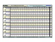
H&C Heat Transfer Sample<strong>PV</strong>E-4293<strong>PV</strong> <strong>Elite</strong> 2012 Licensee: PRESSURE VESSEL ENGINEERINGFileName : <strong>PV</strong>Ecalc-4293-0.0 ------------------------------ Page 21 of 96Internal Pressure <strong>Calculation</strong>s : Step: 5 5:58p Sep 18,2012Element Thickness, Pressure, Diameter and Allowable Stress :| | Int. Press | Nominal | Total Corr| Element | Allowable |From| To | + Liq. Hd | Thickness | Allowance | Diameter | Stress(SE)|| | psig | in. | in. | in. | psi |---------------------------------------------------------------------------Left Head| 150.658 | 0.18750 | 0.062500 | 18.5000 | 18800.0 |Left Chann| 150.657 | 0.18750 | 0.062500 | 18.5000 | 18800.0 |Channel Fl| 150.000 | 1.75000 | 0.062500 | 18.1250 | 17800.0 |Shell| 1400.63 | 0.75000 | 0.062500 | 18.5000 | 18800.0 |Channel Fl| 150.000 | 1.75000 | 0.062500 | 18.1250 | 17800.0 |Channel| 150.657 | 0.18750 | 0.062500 | 18.5000 | 18800.0 |Right Head| 150.658 | 0.18750 | 0.062500 | 18.5000 | 18800.0 |Element Required Thickness and MAWP :| | Design | M.A.W.P. | M.A.P. | Minimum | Required |From| To | Pressure | Corroded | New & Cold | Thickness | Thickness || | psig | psig | psig | in. | in. |----------------------------------------------------------------------------Left Head| 150.000 | 217.957 | 369.279 | 0.16800 | 0.13544 |Left Chann| 150.000 | 254.778 | 408.719 | 0.18750 | 0.13639 |Channel Fl| 150.000 | 161.970 | 194.220 | 1.75000 | 1.68400 |Shell| 1400.00 | 1439.48 | 1675.98 | 0.75000 | 0.73170 |Channel Fl| 150.000 | 161.970 | 194.220 | 1.75000 | 1.68400 |Channel| 150.000 | 254.778 | 408.719 | 0.18750 | 0.13639 |Right Head| 150.000 | 217.957 | 369.279 | 0.16800 | 0.13544 |Summary of Heat Exchanger Maximum Allowable Working Pressures :Note: For ASME UHXdesigns, the following values include MAWPs thatconsider the tubesheet, tubes, tube/tubesheet joint etc. Thesevalues were determined by iteration. Review the tubesheet analysisreport for more information.Shell Side MAWP = 1439.484 psigShell Side MAPnc = 1675.978 psigChannel Side MAWP = 161.970 psigChannel Side MAPnc = 194.220 psigInternal Pressure <strong>Calculation</strong> Results :ASME Code, Section VIII, Division 1, 2010, 2011aElliptical Head From 10 To 20 SA-516 70 ,UCS-66 Crv. Bat 650 FLeft HeadMaterial UNS Number:K02700Required Thickness due to Internal Pressure [tr]:= (P*Do*Kcor)/(2*S*E+2*P*(Kcor-0.1)) per Appendix 1-4 (c)= (150.658*18.5000*0.991)/(2*18800.00*1.00+2*150.658*(0.99-0.1))= 0.0729 + 0.0625 = 0.1354 in.Max. Allowable Working Pressure at given Thickness, corroded [MAWP]:
H&C Heat Transfer Sample<strong>PV</strong>E-4293<strong>PV</strong> <strong>Elite</strong> 2012 Licensee: PRESSURE VESSEL ENGINEERINGFileName : <strong>PV</strong>Ecalc-4293-0.0 ------------------------------ Page 22 of 96Internal Pressure <strong>Calculation</strong>s : Step: 5 5:58p Sep 18,2012Less Operating Hydrostatic Head Pressure of 0.658 psig= (2*S*E*t)/(Kcor*Do-2*t*(Kcor-0.1)) per Appendix 1-4 (c)= (2*18800.00*1.00*0.1055)/(0.991*18.5000-2*0.1055*(0.99-0.1))= 218.615 - 0.658 = 217.957 psigMaximum Allowable Pressure, New and Cold [MAPNC]:= (2*S*E*t)/(K*Do-2*t*(K-0.1)) per Appendix 1-4 (c)= (2*20000.00*1.00*0.1680)/(1.000*18.5000-2*0.1680*(1.000-0.1))= 369.279 psigActual stress at given pressure and thickness, corroded [Sact]:= (P*(Kcor*Do-2*t*(Kcor-0.1)))/(2*E*t)= (150.658*(0.991*18.5000-2*0.1055*(0.991-0.1)))/(2*1.00*0.1055)= 12955.980 psiStraight Flange Required Thickness:= (P*Ro)/(S*E+0.4*P) + c per Appendix 1-1 (a)(1)= (150.658*9.2500)/(18800.00*1.00+0.4*150.658)+0.063= 0.136 in.Straight Flange Maximum Allowable Working Pressure:Less Operating Hydrostatic Head Pressure of 0.658 psig= (S*E*t)/(Ro-0.4*t) per Appendix 1-1 (a)(1)= (18800.00 * 1.00 * 0.1250 )/(9.2500 - 0.4 * 0.1250 )= 255.435 - 0.658 = 254.777 psigFactor K, corroded condition [Kcor]:= ( 2 + ( Inside Diameter/( 2 * Inside Head Depth ))^(2))/6= ( 2 + ( 18.289/( 2 * 4.603 ))^(2))/6= 0.990980Percent Elong. per UCS-79, VIII-1-01-57 (75*tnom/Rf)*(1-Rf/Ro) 4.429 %MDMT <strong>Calculation</strong>s intheKnuckle Portion:Govrn. thk, tg =0.168 , tr =0.074 , c =0.0625 in. , E* =1.00Stress Ratio = tr *(E*)/(tg -c) =0.699 , Temp. Reduction =30 FMin Metal Temp. w/o impact per UCS-66 -20 FMin Metal Temp. at Required thickness (UCS 66.1) -50 FMDMT <strong>Calculation</strong>s intheHeadStraight Flange:Govrn. thk, tg =0.188 , tr =0.075 , c =0.0625 in. , E* =1.00Stress Ratio = tr *(E*)/(tg -c) =0.597 , Temp. Reduction =41 FMin Metal Temp. w/o impact per UCS-66 -20 FMin Metal Temp. at Required thickness (UCS 66.1) -55 FCylindrical Shell From 20 To 30 SA-516 70 ,UCS-66 Crv. Bat 650 FLeft ChannelMaterial UNS Number:K02700Required Thickness due to Internal Pressure [tr]:= (P*Ro) / (S*E+0.4*P) per Appendix 1-1 (a)(1)
H&C Heat Transfer Sample<strong>PV</strong>E-4293<strong>PV</strong> <strong>Elite</strong> 2012 Licensee: PRESSURE VESSEL ENGINEERINGFileName : <strong>PV</strong>Ecalc-4293-0.0 ------------------------------ Page 23 of 96Internal Pressure <strong>Calculation</strong>s : Step: 5 5:58p Sep 18,2012= (150.657*9.2500)/(18800.00*1.00+0.4*150.657)= 0.0739 + 0.0625 = 0.1364 in.Max. Allowable Working Pressure at given Thickness, corroded [MAWP]:Less Operating Hydrostatic Head Pressure of 0.657 psig= (S*E*t)/(Ro-0.4*t) per Appendix 1-1 (a)(1)= (18800.00*1.00*0.1250)/(9.2500-0.4*0.1250)= 255.435 - 0.657 = 254.778 psigMaximum Allowable Pressure, New and Cold [MAPNC]:= (S*E*t)/(Ro-0.4*t) per Appendix 1-1 (a)(1)= (20000.00*1.00*0.1875)/(9.2500-0.4*0.1875)= 408.719 psigActual stress at given pressure and thickness, corroded [Sact]:= (P*(Ro-0.4*t))/(E*t)= (150.657*((9.2500-0.4*0.1250))/(1.00*0.1250)= 11088.338 psiPercent Elongation per UCS-79 (50*tnom/Rf)*(1-Rf/Ro) 1.024 %MinimumDesignMetalTemperatureResults:Govrn. thk, tg =0.188 , tr =0.075 , c =0.0625 in. , E* =1.00Stress Ratio = tr *(E*)/(tg -c) =0.597 , Temp. Reduction =41 FMin Metal Temp. w/o impact per UCS-66 -20 FMin Metal Temp. at Required thickness (UCS 66.1) -55 FCylindrical Shell From 40 To 50 SA-516 70 ,UCS-66 Crv. Bat 650 FShellMaterial UNS Number:K02700Required Thickness due to Internal Pressure [tr]:= (P*Ro) / (S*E+0.4*P) per Appendix 1-1 (a)(1)= (1400.627*9.2500)/(18800.00*1.00+0.4*1400.627)= 0.6692 + 0.0625 = 0.7317 in.Max. Allowable Working Pressure at given Thickness, corroded [MAWP]:Less Operating Hydrostatic Head Pressure of 0.627 psig= (S*E*t)/(Ro-0.4*t) per Appendix 1-1 (a)(1)= (18800.00*1.00*0.6875)/(9.2500-0.4*0.6875)= 1440.111 - 0.627 = 1439.484 psigMaximum Allowable Pressure, New and Cold [MAPNC]:= (S*E*t)/(Ro-0.4*t) per Appendix 1-1 (a)(1)= (20000.00*1.00*0.7500)/(9.2500-0.4*0.7500)= 1675.978 psigActual stress at given pressure and thickness, corroded [Sact]:= (P*(Ro-0.4*t))/(E*t)= (1400.627*((9.2500-0.4*0.6875))/(1.00*0.6875)= 18284.555 psiPercent Elongation per UCS-79 (50*tnom/Rf)*(1-Rf/Ro) 4.225 %
H&C Heat Transfer Sample<strong>PV</strong>E-4293<strong>PV</strong> <strong>Elite</strong> 2012 Licensee: PRESSURE VESSEL ENGINEERINGFileName : <strong>PV</strong>Ecalc-4293-0.0 ------------------------------ Page 24 of 96Internal Pressure <strong>Calculation</strong>s : Step: 5 5:58p Sep 18,2012MinimumDesignMetalTemperatureResults:Govrn. thk, tg =0.750 , tr =0.647 , c =0.0625 in. , E* =1.00Stress Ratio = tr *(E*)/(tg -c) =0.941 , Temp. Reduction =6 FMin Metal Temp. w/o impact per UCS-66 16 FMin Metal Temp. at Required thickness (UCS 66.1) 10 FMin Metal Temp. w/o impact per UG-20(f) -20 FCylindrical Shell From 60 To 70 SA-516 70 ,UCS-66 Crv. Bat 650 FChannelMaterial UNS Number:K02700Required Thickness due to Internal Pressure [tr]:= (P*Ro) / (S*E+0.4*P) per Appendix 1-1 (a)(1)= (150.657*9.2500)/(18800.00*1.00+0.4*150.657)= 0.0739 + 0.0625 = 0.1364 in.Max. Allowable Working Pressure at given Thickness, corroded [MAWP]:Less Operating Hydrostatic Head Pressure of 0.657 psig= (S*E*t)/(Ro-0.4*t) per Appendix 1-1 (a)(1)= (18800.00*1.00*0.1250)/(9.2500-0.4*0.1250)= 255.435 - 0.657 = 254.778 psigMaximum Allowable Pressure, New and Cold [MAPNC]:= (S*E*t)/(Ro-0.4*t) per Appendix 1-1 (a)(1)= (20000.00*1.00*0.1875)/(9.2500-0.4*0.1875)= 408.719 psigActual stress at given pressure and thickness, corroded [Sact]:= (P*(Ro-0.4*t))/(E*t)= (150.657*((9.2500-0.4*0.1250))/(1.00*0.1250)= 11088.338 psiPercent Elongation per UCS-79 (50*tnom/Rf)*(1-Rf/Ro) 1.024 %MinimumDesignMetalTemperatureResults:Govrn. thk, tg =0.188 , tr =0.075 , c =0.0625 in. , E* =1.00Stress Ratio = tr *(E*)/(tg -c) =0.597 , Temp. Reduction =41 FMin Metal Temp. w/o impact per UCS-66 -20 FMin Metal Temp. at Required thickness (UCS 66.1) -55 FElliptical Head From 70 To 80 SA-516 70 ,UCS-66 Crv. Bat 650 FRight HeadMaterial UNS Number:K02700Required Thickness due to Internal Pressure [tr]:= (P*Do*Kcor)/(2*S*E+2*P*(Kcor-0.1)) per Appendix 1-4 (c)= (150.658*18.5000*0.991)/(2*18800.00*1.00+2*150.658*(0.99-0.1))= 0.0729 + 0.0625 = 0.1354 in.
H&C Heat Transfer Sample<strong>PV</strong>E-4293<strong>PV</strong> <strong>Elite</strong> 2012 Licensee: PRESSURE VESSEL ENGINEERINGFileName : <strong>PV</strong>Ecalc-4293-0.0 ------------------------------ Page 25 of 96Internal Pressure <strong>Calculation</strong>s : Step: 5 5:58p Sep 18,2012Max. Allowable Working Pressure at given Thickness, corroded [MAWP]:Less Operating Hydrostatic Head Pressure of 0.658 psig= (2*S*E*t)/(Kcor*Do-2*t*(Kcor-0.1)) per Appendix 1-4 (c)= (2*18800.00*1.00*0.1055)/(0.991*18.5000-2*0.1055*(0.99-0.1))= 218.615 - 0.658 = 217.957 psigMaximum Allowable Pressure, New and Cold [MAPNC]:= (2*S*E*t)/(K*Do-2*t*(K-0.1)) per Appendix 1-4 (c)= (2*20000.00*1.00*0.1680)/(1.000*18.5000-2*0.1680*(1.000-0.1))= 369.279 psigActual stress at given pressure and thickness, corroded [Sact]:= (P*(Kcor*Do-2*t*(Kcor-0.1)))/(2*E*t)= (150.658*(0.991*18.5000-2*0.1055*(0.991-0.1)))/(2*1.00*0.1055)= 12955.980 psiStraight Flange Required Thickness:= (P*Ro)/(S*E+0.4*P) + c per Appendix 1-1 (a)(1)= (150.658*9.2500)/(18800.00*1.00+0.4*150.658)+0.062= 0.136 in.Straight Flange Maximum Allowable Working Pressure:Less Operating Hydrostatic Head Pressure of 0.658 psig= (S*E*t)/(Ro-0.4*t) per Appendix 1-1 (a)(1)= (18800.00 * 1.00 * 0.1250 )/(9.2500 - 0.4 * 0.1250 )= 255.435 - 0.658 = 254.777 psigFactor K, corroded condition [Kcor]:= ( 2 + ( Inside Diameter/( 2 * Inside Head Depth ))^(2))/6= ( 2 + ( 18.289/( 2 * 4.603 ))^(2))/6= 0.990980Percent Elong. per UCS-79, VIII-1-01-57 (75*tnom/Rf)*(1-Rf/Ro) 4.429 %MDMT <strong>Calculation</strong>s intheKnuckle Portion:Govrn. thk, tg =0.168 , tr =0.074 , c =0.0625 in. , E* =1.00Stress Ratio = tr *(E*)/(tg -c) =0.699 , Temp. Reduction =30 FMin Metal Temp. w/o impact per UCS-66 -20 FMin Metal Temp. at Required thickness (UCS 66.1) -50 FMDMT <strong>Calculation</strong>s intheHeadStraight Flange:Govrn. thk, tg =0.188 , tr =0.075 , c =0.0625 in. , E* =1.00Stress Ratio = tr *(E*)/(tg -c) =0.597 , Temp. Reduction =41 FMin Metal Temp. w/o impact per UCS-66 -20 FMin Metal Temp. at Required thickness (UCS 66.1) -55 FNote: Heads and Shells Exempted to -20F (-29C) byparagraph UG-20FHydrostatic Test Pressure Results:Exchanger Shell Side Hydrostatic Test Pressures:
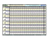
H&C Heat Transfer Sample<strong>PV</strong>E-4293<strong>PV</strong> <strong>Elite</strong> 2012 Licensee: PRESSURE VESSEL ENGINEERINGFileName : <strong>PV</strong>Ecalc-4293-0.0 ------------------------------ Page 26 of 96Internal Pressure <strong>Calculation</strong>s : Step: 5 5:58p Sep 18,2012Pressure per UG99b = 1.3 * M.A.W.P. * Sa/S 1871.329 psigPressure per UG99b[34] = 1.3 * Design Pres * Sa/S 1820.000 psigPressure per UG99c = 1.3 * M.A.P. - Head(Hyd) 2178.771 psigPressure per UG100 = 1.1 * M.A.W.P. * Sa/S 1583.432 psigPressure per PED = 1.43 * MAWP 2058.462 psigExchanger Channel Side Hydrostatic Test Pressures:Pressure per UG99b = 1.3 * M.A.W.P. * Sa/S 210.561 psigPressure per UG99b[34] = 1.3 * Design Pres * Sa/S 195.000 psigPressure per UG99c = 1.3 * M.A.P. - Head(Hyd) 252.486 psigPressure per UG100 = 1.1 * M.A.W.P. * Sa/S 178.167 psigPressure per PED = 1.43 * MAWP 231.617 psigUG-99(b) Note 34, Test Pressure <strong>Calculation</strong> [Shell Side]:= Test Factor * Design Pressure * Stress Ratio= 1.3 * 1400.000 * 1.000= 1820.000 psigUG-99(b) Note 34, Test Pressure <strong>Calculation</strong> [Channel Side]:= Test Factor * Design Pressure * Stress Ratio= 1.3 * 150.000 * 1.000= 195.000 psigHorizontal Test performed per: UG-99b (Note 34)Please note that Nozzle, Shell, Head, Flange, etc MAWPs are all consideredwhen determining the hydrotest pressure for those test types that are basedon the MAWP of the vessel.Stresses on Elements due to Hydrostatic Test Pressure:From To Stress Allowable Ratio PressureLeft Head 10597.3 26000.0 0.408 195.67Left Channel 9574.7 26000.0 0.368 195.67Shell 21726.6 26000.0 0.836 1820.67Channel 9574.7 26000.0 0.368 195.67Right Head 10597.3 26000.0 0.408 195.67Elements Suitable for Internal Pressure.<strong>PV</strong><strong>Elite</strong> is atrademarkof IntergraphCADWorx&AnalysisSolutions, Inc. 2012
H&C Heat Transfer Sample<strong>PV</strong>E-4293<strong>PV</strong> <strong>Elite</strong> 2012 Licensee: PRESSURE VESSEL ENGINEERINGFileName : <strong>PV</strong>Ecalc-4293-0.0 ------------------------------ Page 27 of 96External Pressure <strong>Calculation</strong>s : Step: 6 5:58p Sep 18,2012External Pressure <strong>Calculation</strong> Results :ASME Code, Section VIII, Division 1, 2010, 2011aElliptical Head From 10 to 20 Ext. Chart: CS-2 at 650 FLeft HeadElastic Modulus from Chart: CS-2 at 650 F:0.251E+08 psiResults for Maximum Allowable External Pressure (MAEP):Tca OD D/t Factor A B0.105 18.50 175.36 0.0007920 8040.84EMAP = B/(K0*D/t) = 8040.8364/(0.9000 *175.3555 ) = 50.9494 psigCheck the requirements of UG-33(a)(1) using P=1.67 *External Designpressure for this head.Material UNS Number:K02700Max. Allowable Working Pressure at given Thickness, corroded [MAWP]:= ((2*S*E*t)/(Kcor*Do-2*t*(Kcor-0.1)))/1.67 per Appendix 1-4 (c)= ((2*18800.00*1.00*0.1055)/(0.991*18.5000-2*0.1055*(0.99-0.1)))/1.67= 130.907 psigMaximum Allowable External Pressure [MAEP]:= min( MAEP, MAWP )= min( 50.95 , 130.9073 )= 50.949 psigCylindrical Shell From 20 to 30 Ext. Chart: CS-2 at 650 FLeft ChannelElastic Modulus from Chart: CS-2 at 650 F:0.251E+08 psiResults for Maximum Allowable External Pressure (MAEP):Tca OD SLEN D/t L/D Factor A B0.125 18.50 11.26 148.00 0.6087 0.0012594 8959.65EMAP = (4*B)/(3*(D/t)) = (4*8959.6514 )/(3*148.0000 ) = 80.7176 psigResults for Maximum Stiffened Length (Slen):Tca OD SLEN D/t L/D Factor A B0.125 18.50 11.26 148.00 0.6087 0.0012594 8959.65EMAP = (4*B)/(3*(D/t)) = (4*8959.6514 )/(3*148.0000 ) = 80.7176 psigCylindrical Shell From 40 to 50 Ext. Chart: CS-2 at 650 FShellElastic Modulus from Chart: CS-2 at 650 F:0.251E+08 psiResults for Maximum Allowable External Pressure (MAEP):Tca OD SLEN D/t L/D Factor A B
H&C Heat Transfer Sample<strong>PV</strong>E-4293<strong>PV</strong> <strong>Elite</strong> 2012 Licensee: PRESSURE VESSEL ENGINEERINGFileName : <strong>PV</strong>Ecalc-4293-0.0 ------------------------------ Page 29 of 96External Pressure <strong>Calculation</strong>s : Step: 6 5:58p Sep 18,2012External Pressure <strong>Calculation</strong>s| | Section | Outside | Corroded | Factor | Factor |From| To | Length | Diameter | Thickness | A | B || | ft. | in. | in. | | psi |---------------------------------------------------------------------------10| 20| No Calc | 18.5000 | 0.10550 | 0.00079204 | 8040.84 |20| 30| 0.93844 | 18.5000 | 0.12500 | 0.0012594 | 8959.65 |30| 40| No Calc | ... | 1.68750 | No Calc | No Calc |40| 50| 7.66700 | 18.5000 | 0.68750 | 0.0018108 | 9670.06 |50| 60| No Calc | ... | 1.68750 | No Calc | No Calc |60| 70| 0.93844 | 18.5000 | 0.12500 | 0.0012594 | 8959.65 |70| 80| No Calc | 18.5000 | 0.10550 | 0.00079204 | 8040.84 |External Pressure <strong>Calculation</strong>s| | External | External | External | External |From| To | Actual T. | Required T.|Des. Press. | M.A.W.P. || | in. | in. | psig | psig |----------------------------------------------------------------10| 20| 0.16800 | 0.12500 | ... | 50.9494 |20| 30| 0.18750 | No Calc | ... | 80.7176 |30| 40| 1.75000 | 1.66400 | ... | No Calc |40| 50| 0.75000 | 0.18647 | 15.0000 | 479.147 |50| 60| 1.75000 | 1.66400 | ... | No Calc |60| 70| 0.18750 | No Calc | ... | 80.7176 |70| 80| 0.16800 | 0.12500 | ... | 50.9494 |Minimum 50.949External Pressure <strong>Calculation</strong>s| | Actual Len.| Allow. Len.| Ring Inertia | Ring Inertia |From| To | Bet. Stiff.| Bet. Stiff.| Required | Available || | ft. | ft. | in**4 | in**4 |-------------------------------------------------------------------10| 20| No Calc | No Calc | No Calc | No Calc |20| 30| 0.93844 | No Calc | No Calc | No Calc |30| 40| No Calc | No Calc | No Calc | No Calc |40| 50| 7.66700 | 240.842 | No Calc | No Calc |50| 60| No Calc | No Calc | No Calc | No Calc |60| 70| 0.93844 | No Calc | No Calc | No Calc |70| 80| No Calc | No Calc | No Calc | No Calc |Elements Suitable for External Pressure.<strong>PV</strong><strong>Elite</strong> is atrademarkof IntergraphCADWorx&AnalysisSolutions, Inc. 2012
H&C Heat Transfer Sample<strong>PV</strong>E-4293<strong>PV</strong> <strong>Elite</strong> 2012 Licensee: PRESSURE VESSEL ENGINEERINGFileName : <strong>PV</strong>Ecalc-4293-0.0 ------------------------------ Page 30 of 96Element and Detail Weights : Step: 7 5:58p Sep 18,2012Element and Detail Weights| | Element | Element | Corroded | Corroded | Extra due |From| To | Metal Wgt. | ID Volume |Metal Wgt. | ID Volume | Misc % || | lb. | in³ | lb. | in³ | lb. |---------------------------------------------------------------------------10| 20| 24.4461 | 1043.49 | 16.2974 | 1063.37 | ... |20| 30| 26.7051 | 2257.12 | 17.8642 | 2288.36 | ... |30| 40| 93.9645 | 748.044 | 91.0590 | 752.062 | ... |40| 50| 1088.94 | 13368.1 | 1001.71 | 13676.3 | ... |50| 60| 93.9645 | 748.044 | 91.0590 | 752.062 | ... |60| 70| 26.7051 | 2257.12 | 17.8642 | 2288.36 | ... |70| 80| 24.4461 | 1043.49 | 16.2974 | 1063.37 | ... |---------------------------------------------------------------------------Total 1379 21465 1252 21883 0For elements specified as shell side elements, the volume(s) shownabove for those elements, reflects the displacement of the tubes.Weight of Details| | Weight of | X Offset, | Y Offset, |From|Type| Detail | Dtl. Cent. |Dtl. Cent. | Description| | lb. | ft. | ft. |-------------------------------------------------10|Liqd| 37.6815 | -0.12614 | ... | HEAD20|Liqd| 81.5071 | 0.77950 | ... | CHANNEL20|Nozl| 29.8733 | 0.36000 | 0.94271 | T1/T240|Sadl| 56.7760 | 1.59890 | 1.35417 | Lft Sdl40|Sadl| 56.7760 | 6.40000 | 1.35417 | Rgt Sdl40|Liqd| 482.735 | 3.83350 | -0.013002 | SHELL40|Nozl| 47.5039 | 0.50000 | 0.85417 | S240|Nozl| 140.290 | 7.29000 | 0.98438 | S140|Nozl| 29.1602 | 0.50000 | 0.80729 | S360|Liqd| 81.5071 | 0.36450 | ... | CHANNEL60|Nozl| 4.59655 | 0.50000 | 0.81000 | T3 & T470|Liqd| 37.6815 | 0.20944 | ... | HEAD30|FTsh| 199.263 | 0.32292 | ... | Tubesheet30|Tube| 862.075 | 4.23958 | ... |30|RTsh| 199.263 | 8.15625 | ... |Total Weight of Each Detail TypeTotal Weight of Saddles 113.6Total Weight of Liquid 721.1Total Weight of Nozzles 251.4Total Weight of Exchanger Components 1260.6Total Weight of Liquid in Tubes 173.2---------------------------------------------------------------Sum of the Detail Weights 2519.8 lb.Weight SummationFabricated Shop Test Shipping Erected Empty Operating------------------------------------------------------------------------------
H&C Heat Transfer Sample<strong>PV</strong>E-4293<strong>PV</strong> <strong>Elite</strong> 2012 Licensee: PRESSURE VESSEL ENGINEERINGFileName : <strong>PV</strong>Ecalc-4293-0.0 ------------------------------ Page 31 of 96Element and Detail Weights : Step: 7 5:58p Sep 18,20121379.2 3004.7 1379.2 3004.7 1379.2 3004.7113.6 775.1 113.6 ... 113.6 721.1251.4 ... 251.4 ... ... ...... 173.2 ... ... ... ...... ... ... ... ... ...... ... ... ... ... ...... ... ... ... 251.4 173.21260.6 ... 1260.6 ... ... ...... ... ... ... 1260.6 ...------------------------------------------------------------------------------3004.7 3953.0 3004.7 3004.7 3004.7 3899.0 lb.Note: The shipping total has been modified because some items havebeen specified as being installed in the shop.Weight SummaryFabricated Wt. - Bare Weight W/O Removable Internals 3004.7 lb.Shop Test Wt. - Fabricated Weight + Water ( Full ) 3953.0 lb.Shipping Wt. - Fab. Wt + Rem. Intls.+ Shipping App. 3004.7 lb.Erected Wt. - Fab. Wt + Rem. Intls.+ Insul. (etc) 3004.7 lb.Ope. Wt. no Liq - Fab. Wt + Intls. + Details + Wghts. 3004.7 lb.Operating Wt. - Empty Wt + Operating Liq. Uncorroded 3899.0 lb.Oper. Wt. + CA - Corr Wt. + Operating Liquid 3772.0 lb.Field Test Wt. - Empty Weight + Water (Full) 3953.0 lb.Exchanger Tube DataVolume of Exchanger tubes : 4795.2 in³Weight of Ope Liq in tubes : 173.2 lb.Weight of Water in tubes : 173.2 lb.Note: The Corroded Weight and thickness are used in the HorizontalVessel Analysis (Ope Case) and Earthquake Load <strong>Calculation</strong>s.Outside Surface Areas of Elements| | Surface |From| To | Area || | in² |----------------------------10| 20| 430.779 |20| 30| 508.429 |30| 40| 372.954 |40| 50| 5347.22 |50| 60| 372.954 |60| 70| 508.429 |70| 80| 430.779 |---------------------------------------------------Total 7971.545 in² [55.4 Square Feet ]<strong>PV</strong><strong>Elite</strong> is atrademarkof IntergraphCADWorx&AnalysisSolutions, Inc. 2012
H&C Heat Transfer Sample<strong>PV</strong>E-4293<strong>PV</strong> <strong>Elite</strong> 2012 Licensee: PRESSURE VESSEL ENGINEERINGFileName : <strong>PV</strong>Ecalc-4293-0.0 ------------------------------ Page 32 of 96Nozzle Flange MAWP : Step: 8 5:58p Sep 18,2012Nozzle Flange MAWP Results :Nozzle----- Flange RatingDescription Operating Ambient Temperature Class Grade|Grouppsig psig F----------------------------------------------------------------------------T1/T2 550.0 740.0 650 300 GR 1.1S2 1650.0 2220.0 650 900 GR 1.1S1 1650.0 2220.0 650 900 GR 1.1S3 1650.0 2220.0 650 900 GR 1.1T3 & T4 550.0 740.0 650 300 GR 1.1ShellsideFlangeRatingLowest Flange Pressure Rating was (Ope)[ShellSide]:Lowest Flange Pressure Rating was (Amb)[ShellSide]:ChannelsideFlangeRatingLowest Flange Pressure Rating was (Ope)[TubeSide ]:Lowest Flange Pressure Rating was (Amb)[TubeSide ]:1650.000 psig2220.000 psig550.000 psig740.000 psigNote: ANSI Ratings are per ANSI/ASME B16.5 2009 Edition<strong>PV</strong><strong>Elite</strong> is atrademarkof IntergraphCADWorx&AnalysisSolutions, Inc. 2012
H&C Heat Transfer Sample<strong>PV</strong>E-4293<strong>PV</strong> <strong>Elite</strong> 2012 Licensee: PRESSURE VESSEL ENGINEERINGFileName : <strong>PV</strong>Ecalc-4293-0.0 ------------------------------ Page 33 of 96Center of Gravity <strong>Calculation</strong> : Step: 9 5:58p Sep 18,2012Shop/Field Installation Options :Note : The CG is computed from the first Element From NodeCenter of Gravity of Saddles 5.218 ft.Center of Gravity of Liquid 5.099 ft.Center of Gravity of Nozzles 5.503 ft.Center of Gravity of Tubesheet(s) 5.052 ft.Center of Gravity of Tubes 5.052 ft.Center of Gravity of Bare Shell New and Cold 5.052 ft.Center of Gravity of Bare Shell Corroded 5.052 ft.Vessel CG in the Operating Condition 5.098 ft.Vessel CG in the Fabricated (Shop/Empty) Condition 5.096 ft.<strong>PV</strong><strong>Elite</strong> is atrademarkof IntergraphCADWorx&AnalysisSolutions, Inc. 2012
H&C Heat Transfer Sample<strong>PV</strong>E-4293<strong>PV</strong> <strong>Elite</strong> 2012 Licensee: PRESSURE VESSEL ENGINEERINGFileName : <strong>PV</strong>Ecalc-4293-0.0 ------------------------------ Page 34 of 96Horizontal Vessel Analysis (Ope.) : Step: 10 5:58p Sep 18,2012ASME Horizontal Vessel Analysis: Stresses for the Left Saddle(per ASME Sec. VIII Div. 2based on the Zick method.)Horizontal Vessel Stress <strong>Calculation</strong>s : Operating CaseNote: Wear Pad Width (5.00) is less than 1.56*sqrt(rm*t)and less than 2a. The wear plate will be ignored.Minimum Wear Plate Width to be considered in analysis [b1]:= min( b + 1.56*sqrt( Rm * t ), 2a )= min( 4.000 + 1.56*sqrt( 8.9062 * 0.6875 ), 2 * 6.625 )= 7.8602 in.Input and CalculatedValues:Vessel Mean Radius Rm 8.91 in.Stiffened Vessel Length per 4.15.6 L 7.67 ft.Distance from Saddle to Vessel tangent a 6.62 in.Saddle Width b 4.00 in.Saddle Bearing Angle theta 120.00 degreesShell Allowable Stress used in <strong>Calculation</strong> 18800.00 psiHead Allowable Stress used in <strong>Calculation</strong> 17800.00 psiCircumferential Efficiency in Plane of Saddle 1.00Circumferential Efficiency at Mid-Span 1.00Saddle Force Q, Operating Case1696.94 lb.Horizontal Vessel Analysis Results: Actual Allowable-------------------------------------------------------------------Long. Stress at Top of Midspan 8903.77 18800.00 psiLong. Stress at Bottom of Midspan 9236.72 18800.00 psiLong. Stress at Top of Saddles 9074.51 18800.00 psiLong. Stress at Bottom of Saddles 9067.88 18800.00 psiTangential Shear in Shell 277.72 15040.00 psiCirc. Stress at Horn of Saddle 253.77 23500.00 psiCirc. Compressive Stress in Shell 23.87 18800.00 psiLoad Combination Results for Q+Wind or Seismic [Q]:= Saddle Load + Max( Fwl, Fwt, Fsl, Fst )= 1696 + Max( 0 , 0 , 0 , 0 )= 1696.9 lb.Summaryof Loadsat thebase of thisSaddle:Vertical Load (including saddle weight) 1753.71 lb.Transverse Shear Load Saddle0.00 lb.Longitudinal Shear Load Saddle0.00 lb.Formulas and Substitutions for Horizontal Vessel Analysis:Note: Wear Plate is Welded to the Shell, k=0.1TheComputedK valuesfromTable4.15.1:K1 = 0.1066 K2 = 1.1707 K3 = 0.8799 K4 = 0.4011
H&C Heat Transfer Sample<strong>PV</strong>E-4293<strong>PV</strong> <strong>Elite</strong> 2012 Licensee: PRESSURE VESSEL ENGINEERINGFileName : <strong>PV</strong>Ecalc-4293-0.0 ------------------------------ Page 35 of 96Horizontal Vessel Analysis (Ope.) : Step: 10 5:58p Sep 18,2012K5 = 0.7603 K6 = 0.0529 K7 = 0.0325 K8 = 0.3405K9 = 0.2711 K10 = 0.0581 K1* = 0.1923Note: Dimension ais greater than or equal to Rm / 2.Moment per Equation 4.15.3 [M1]:= -Q*a [1 - (1- a/L + (R²-h2²)/(2a*L))/(1+(4h2)/3L)]= -1696*0.55[1-(1-0.55/7.67+(0.742²-0.000²)/(2*0.55*7.67))/(1+(4*0.00)/(3*7.67))]= -6.5 ft.lb.Moment per Equation 4.15.4 [M2]:= Q*L/4(1+2(R²-h2²)/(L²))/(1+(4h2)/( 3L))-4a/L= 1696*7.7/4(1+2(0.742²-0.000²)/(7.67²))/(1+(4*0.000)/(3*7.667))-4*0.55/7.67= 2376.7 ft.lb.Longitudinal Stress at Top of Shell (4.15.6) [Sigma1]:= P * Rm/(2t) - M2/(pi*Rm²t)= 1400.32 * 8.906/(2*0.688 ) - 28520.5/(pi*8.9²*0.688 )= 8903.77 psiLongitudinal Stress at Bottom of Shell (4.15.7) [Sigma2]:= P * Rm/(2t) + M2/(pi * Rm² * t)= 1400.32 * 8.906/(2 * 0.688 ) + 28520.5/(pi * 8.9² * 0.688 )= 9236.72 psiLongitudinal Stress at Top of Shell at Support (4.15.10) [Sigma*3]:= P * Rm/(2t) - M1/(K1*pi*Rm²t)= 1400.32*8.906/(2*0.688)--78.0/(0.1066*pi*8.9²*0.688)= 9074.51 psiLongitudinal Stress at Bottom of Shell at Support (4.15.11) [Sigma*4]:= P * Rm/(2t) + M1/(K1* * pi * Rm² * t)= 1400.32*8.906/(2*0.688)+-78.0/(0.1923*pi*8.9²*0.688)= 9067.88 psiMaximum Shear Force in the Saddle (4.15.5) [T]:= Q(L-2a)/(L+(4*h2/3))= 1696 ( 7.67 - 2 * 0.55 )/(7.67 + ( 4 * 0.00/3))= 1452.6 lb.Shear Stress in the shell no rings, not stiffened (4.15.14) [tau2]:= K2 * T / ( Rm * t )= 1.1707 * 1452.55/( 8.9062 * 0.6875 )= 277.72 psiDecay Length (4.15.22) [x1,x2]:= 0.78 * sqrt( Rm * t )= 0.78 * sqrt( 8.906 * 0.688 )= 1.930 in.Circumferential Stress in shell, no rings (4.15.23) [sigma6]:= -K5 * Q * k / ( t * ( b + X1 + X2 ) )= -0.7603 * 1696 * 0.1/( 0.688 * ( 4.00 + 1.93 + 1.93 ) )= -23.87 psi
H&C Heat Transfer Sample<strong>PV</strong>E-4293<strong>PV</strong> <strong>Elite</strong> 2012 Licensee: PRESSURE VESSEL ENGINEERINGFileName : <strong>PV</strong>Ecalc-4293-0.0 ------------------------------ Page 36 of 96Horizontal Vessel Analysis (Ope.) : Step: 10 5:58p Sep 18,2012Circ. Comp. Stress at Horn of Saddle, L>=8Rm (4.15.24) [sigma7]:= -Q/(4*t*(b+X1+X2)) - 3*K7*Q/(2*t²)= -1696/(4*0.688 *(4.000 +1.930 +1.930 )) -3*0.0325 *1696/(2*0.688²)= -253.77 psiEffective reinforcing plate width (4.15.1) [B1]:= min( b + 1.56 * sqrt( Rm * t ), 2a )= min( 4.00 + 1.56 * sqrt( 8.906 * 0.688 ), 2 * 6.625 )= 7.86 in.Free Un-Restrained Thermal Expansion between the Saddles [Exp]:= Alpha * Ls * ( Design Temperature - Ambient Temperature )= 0.750E-05 * 57.613 * ( 650.0 - 70.0 )= 0.251 in.Results for Vessel Ribs, Web and Base:Baseplate Length Bplen 16.4000 in.Baseplate Thickness Bpthk 0.2500 in.Baseplate Width Bpwid 4.0000 in.Number of Ribs ( inc. outside ribs ) Nribs 2Rib Thickness Ribtk 0.2500 in.Web Thickness Webtk 0.2500 in.Web Location Webloc SideMoment of Inertia of Saddle - Lateral DirectionY A AY IoShell 0.3438 6.0397 2.0761 0.9516Wearplate 0.8125 1.2500 1.0156 0.8317Web 12.3438 5.7031 70.3979 1116.3051BasePlate 23.8750 1.0000 23.8750 570.0208Totals 37.3750 13.9928 97.3647 1688.1091Value C1 = Sumof(Ay)/Sumof(A) = 6.9582 in.Value I = Sumof(Io) - C1*Sumof(Ay) = 1010.6252 in**4Value As = Sumof(A) - Ashell = 7.9531 in²K1 = (1+Cos(beta)-.5*Sin(beta)² )/(pi-beta+Sin(beta)*Cos(beta)) = 0.2035Fh = K1 * Q = 0.2035 * 1696.937 = 345.3636 lb.Tension Stress, St = ( Fh/As ) = 43.4249 psiAllowed Stress, Sa = 0.6 * Yield Str = 21600.0000 psid = B - R*Sin(theta) / theta = 25.4814 in.Bending Moment, M = Fh * d = 733.3613 ft.lb.Bending Stress, Sb = ( M * C1 / I ) = 60.5908 psiAllowed Stress, Sa = 2/3 * Yield Str = 24000.0000 psiMinimumThicknessof BaseplateperMoss := ( 3 * ( Q + Saddle_Wt ) * BasePlateWidth / ( 2 * BasePlateLength *AllStress ))½= ( 3 * (1696 + 56 ) * 4.00/( 2 * 16.400 * 24000.000 ))½= 0.164 in.
H&C Heat Transfer Sample<strong>PV</strong>E-4293<strong>PV</strong> <strong>Elite</strong> 2012 Licensee: PRESSURE VESSEL ENGINEERINGFileName : <strong>PV</strong>Ecalc-4293-0.0 ------------------------------ Page 37 of 96Horizontal Vessel Analysis (Ope.) : Step: 10 5:58p Sep 18,2012<strong>Calculation</strong> of Axial Load, Intermediate Values and Compressive StressEffective Baseplate Length [e]:= ( Bplen - Clearance ) / ( Nribs - 1)= ( 16.4000 - 1.0 )/( 2 - 1 ) = 15.4000 in.Baseplate Pressure Area [Ap]:= e * Bpwid / 2= 15.4000 * 4.0000/2 = 30.8000 in²Axial Load [P]:= Ap * Bp= 30.8 * 25.87 = 796.7 lb.Area of the Rib and Web [Ar]:= ( Bpwid - Clearance - Webtk ) * Ribtk + e/2 * Webtk= ( 4.000 - 1.0 - 0.250 ) * 0.250 + 15.4000/2 * 0.250= 2.612 in²Compressive Stress [Sc]:= P/Ar= 796.7/2.6125 = 304.9695 psiCheck of Outside Ribs:Inertia of Saddle, Outer Ribs - Longitudinal DirectionY A AY Ay² IoRib 1.6250 0.8125 1.3203 0.9040 0.8932Web 0.1250 1.9250 0.2406 0.3816 0.0201Values 0.5702 2.7375 1.5609 1.2855 0.9133Bending Moment [Rm]:= Fl /( 2 * Bplen ) * e * rl / 2= 0.0/( 2 * 16.40 ) * 15.400 * 27.94/2= 0.000 ft.lb.KL/R < Cc ( 30.4524 < 126.0993 ) per AISC E2-1Sca = (1-(Klr)²/(2*Cc²))*Fy/(5/3+3*(Klr)/(8*Cc)-(Klr³)/(8*Cc³)Sca = ( 1-( 30.45 )²/(2 * 126.10² )) * 36000/( 5/3+3*(30.45 )/(8* 126.10 )-( 30.45³)/(8*126.10³)Sca = 19909.37 psiAISC Unity Check on Outside Ribs (must be
H&C Heat Transfer Sample<strong>PV</strong>E-4293<strong>PV</strong> <strong>Elite</strong> 2012 Licensee: PRESSURE VESSEL ENGINEERINGFileName : <strong>PV</strong>Ecalc-4293-0.0 ------------------------------ Page 38 of 96Horizontal Vessel Analysis (Ope.) : Step: 10 5:58p Sep 18,2012Input and CalculatedValues:Vessel Mean Radius Rm 8.91 in.Stiffened Vessel Length per 4.15.6 L 7.67 ft.Distance from Saddle to Vessel tangent a 6.62 in.Saddle Width b 4.00 in.Saddle Bearing Angle theta 120.00 degreesShell Allowable Stress used in <strong>Calculation</strong> 18800.00 psiHead Allowable Stress used in <strong>Calculation</strong> 17800.00 psiCircumferential Efficiency in Plane of Saddle 1.00Circumferential Efficiency at Mid-Span 1.00Saddle Force Q, Operating Case1961.51 lb.Horizontal Vessel Analysis Results: Actual Allowable-------------------------------------------------------------------Long. Stress at Top of Midspan 8877.81 18800.00 psiLong. Stress at Bottom of Midspan 9262.67 18800.00 psiLong. Stress at Top of Saddles 9075.18 18800.00 psiLong. Stress at Bottom of Saddles 9067.51 18800.00 psiTangential Shear in Shell 321.02 15040.00 psiCirc. Stress at Horn of Saddle 293.34 23500.00 psiCirc. Compressive Stress in Shell 27.60 18800.00 psiLoad Combination Results for Q+Wind or Seismic [Q]:= Saddle Load + Max( Fwl, Fwt, Fsl, Fst )= 1961 + Max( 0 , 0 , 0 , 0 )= 1961.5 lb.Summaryof Loadsat thebase of thisSaddle:Vertical Load (including saddle weight) 2018.29 lb.Transverse Shear Load Saddle0.00 lb.Longitudinal Shear Load Saddle0.00 lb.Formulas and Substitutions for Horizontal Vessel Analysis:Note: Wear Plate is Welded to the Shell, k=0.1TheComputedK valuesfromTable4.15.1:K1 = 0.1066 K2 = 1.1707 K3 = 0.8799 K4 = 0.4011K5 = 0.7603 K6 = 0.0529 K7 = 0.0325 K8 = 0.3405K9 = 0.2711 K10 = 0.0581 K1* = 0.1923Note: Dimension ais greater than or equal to Rm / 2.Moment per Equation 4.15.3 [M1]:= -Q*a [1 - (1- a/L + (R²-h2²)/(2a*L))/(1+(4h2)/3L)]= -1961*0.55[1-(1-0.55/7.67+(0.742²-0.000²)/(2*0.55*7.67))/(1+(4*0.00)/(3*7.67))]= -7.5 ft.lb.Moment per Equation 4.15.4 [M2]:= Q*L/4(1+2(R²-h2²)/(L²))/(1+(4h2)/( 3L))-4a/L
H&C Heat Transfer Sample<strong>PV</strong>E-4293<strong>PV</strong> <strong>Elite</strong> 2012 Licensee: PRESSURE VESSEL ENGINEERINGFileName : <strong>PV</strong>Ecalc-4293-0.0 ------------------------------ Page 39 of 96Horizontal Vessel Analysis (Ope.) : Step: 10 5:58p Sep 18,2012= 1961*7.7/4(1+2(0.742²-0.000²)/(7.67²))/(1+(4*0.000)/(3*7.667))-4*0.55/7.67= 2747.3 ft.lb.Longitudinal Stress at Top of Shell (4.15.6) [Sigma1]:= P * Rm/(2t) - M2/(pi*Rm²t)= 1400.32 * 8.906/(2*0.688 ) - 32967.2/(pi*8.9²*0.688 )= 8877.81 psiLongitudinal Stress at Bottom of Shell (4.15.7) [Sigma2]:= P * Rm/(2t) + M2/(pi * Rm² * t)= 1400.32 * 8.906/(2 * 0.688 ) + 32967.2/(pi * 8.9² * 0.688 )= 9262.67 psiLongitudinal Stress at Top of Shell at Support (4.15.10) [Sigma*3]:= P * Rm/(2t) - M1/(K1*pi*Rm²t)= 1400.32*8.906/(2*0.688)--90.2/(0.1066*pi*8.9²*0.688)= 9075.18 psiLongitudinal Stress at Bottom of Shell at Support (4.15.11) [Sigma*4]:= P * Rm/(2t) + M1/(K1* * pi * Rm² * t)= 1400.32*8.906/(2*0.688)+-90.2/(0.1923*pi*8.9²*0.688)= 9067.51 psiMaximum Shear Force in the Saddle (4.15.5) [T]:= Q(L-2a)/(L+(4*h2/3))= 1961 ( 7.67 - 2 * 0.55 )/(7.67 + ( 4 * 0.00/3))= 1679.0 lb.Shear Stress in the shell no rings, not stiffened (4.15.14) [tau2]:= K2 * T / ( Rm * t )= 1.1707 * 1679.02/( 8.9062 * 0.6875 )= 321.02 psiDecay Length (4.15.22) [x1,x2]:= 0.78 * sqrt( Rm * t )= 0.78 * sqrt( 8.906 * 0.688 )= 1.930 in.Circumferential Stress in shell, no rings (4.15.23) [sigma6]:= -K5 * Q * k / ( t * ( b + X1 + X2 ) )= -0.7603 * 1961 * 0.1/( 0.688 * ( 4.00 + 1.93 + 1.93 ) )= -27.60 psiCirc. Comp. Stress at Horn of Saddle, L>=8Rm (4.15.24) [sigma7]:= -Q/(4*t*(b+X1+X2)) - 3*K7*Q/(2*t²)= -1961/(4*0.688 *(4.000 +1.930 +1.930 )) -3*0.0325 *1961/(2*0.688²)= -293.34 psiEffective reinforcing plate width (4.15.1) [B1]:= min( b + 1.56 * sqrt( Rm * t ), 2a )= min( 4.00 + 1.56 * sqrt( 8.906 * 0.688 ), 2 * 6.625 )= 7.86 in.Results for Vessel Ribs, Web and Base
H&C Heat Transfer Sample<strong>PV</strong>E-4293<strong>PV</strong> <strong>Elite</strong> 2012 Licensee: PRESSURE VESSEL ENGINEERINGFileName : <strong>PV</strong>Ecalc-4293-0.0 ------------------------------ Page 40 of 96Horizontal Vessel Analysis (Ope.) : Step: 10 5:58p Sep 18,2012Baseplate Length Bplen 16.4000 in.Baseplate Thickness Bpthk 0.2500 in.Baseplate Width Bpwid 4.0000 in.Number of Ribs ( inc. outside ribs ) Nribs 2Rib Thickness Ribtk 0.2500 in.Web Thickness Webtk 0.2500 in.Web Location Webloc SideMoment of Inertia of Saddle - Lateral DirectionY A AY IoShell 0.3438 6.0397 2.0761 0.9516Wearplate 0.8125 1.2500 1.0156 0.8317Web 12.3438 5.7031 70.3979 1116.3051BasePlate 23.8750 1.0000 23.8750 570.0208Totals 37.3750 13.9928 97.3647 1688.1091Value C1 = Sumof(Ay)/Sumof(A) = 6.9582 in.Value I = Sumof(Io) - C1*Sumof(Ay) = 1010.6252 in**4Value As = Sumof(A) - Ashell = 7.9531 in²K1 = (1+Cos(beta)-.5*Sin(beta)² )/(pi-beta+Sin(beta)*Cos(beta)) = 0.2035Fh = K1 * Q = 0.2035 * 1961.509 = 399.2097 lb.Tension Stress, St = ( Fh/As ) = 50.1953 psiAllowed Stress, Sa = 0.6 * Yield Str = 21600.0000 psid = B - R*Sin(theta) / theta = 25.4814 in.Bending Moment, M = Fh * d = 847.7009 ft.lb.Bending Stress, Sb = ( M * C1 / I ) = 70.0376 psiAllowed Stress, Sa = 2/3 * Yield Str = 24000.0000 psiMinimumThicknessof BaseplateperMoss := ( 3 * ( Q + Saddle_Wt ) * BasePlateWidth / ( 2 * BasePlateLength *AllStress ))½= ( 3 * (1961 + 56 ) * 4.00/( 2 * 16.400 * 24000.000 ))½= 0.175 in.<strong>Calculation</strong> of Axial Load, Intermediate Values and Compressive StressEffective Baseplate Length [e]:= ( Bplen - Clearance ) / ( Nribs - 1)= ( 16.4000 - 1.0 )/( 2 - 1 ) = 15.4000 in.Baseplate Pressure Area [Ap]:= e * Bpwid / 2= 15.4000 * 4.0000/2 = 30.8000 in²Axial Load [P]:= Ap * Bp= 30.8 * 29.90 = 921.0 lb.Area of the Rib and Web [Ar]:= ( Bpwid - Clearance - Webtk ) * Ribtk + e/2 * Webtk= ( 4.000 - 1.0 - 0.250 ) * 0.250 + 15.4000/2 * 0.250
H&C Heat Transfer Sample<strong>PV</strong>E-4293<strong>PV</strong> <strong>Elite</strong> 2012 Licensee: PRESSURE VESSEL ENGINEERINGFileName : <strong>PV</strong>Ecalc-4293-0.0 ------------------------------ Page 41 of 96Horizontal Vessel Analysis (Ope.) : Step: 10 5:58p Sep 18,2012= 2.612 in²Compressive Stress [Sc]:= P/Ar= 921.0/2.6125 = 352.5177 psiCheck of Outside Ribs:Inertia of Saddle, Outer Ribs - Longitudinal DirectionY A AY Ay² IoRib 1.6250 0.8125 1.3203 0.9040 0.8932Web 0.1250 1.9250 0.2406 0.3816 0.0201Values 0.5702 2.7375 1.5609 1.2855 0.9133Bending Moment [Rm]:= Fl /( 2 * Bplen ) * e * rl / 2= 0.0/( 2 * 16.40 ) * 15.400 * 27.94/2= 0.000 ft.lb.KL/R < Cc ( 30.4524 < 126.0993 ) per AISC E2-1Sca = (1-(Klr)²/(2*Cc²))*Fy/(5/3+3*(Klr)/(8*Cc)-(Klr³)/(8*Cc³)Sca = ( 1-( 30.45 )²/(2 * 126.10² )) * 36000/( 5/3+3*(30.45 )/(8* 126.10 )-( 30.45³)/(8*126.10³)Sca = 19909.37 psiAISC Unity Check on Outside Ribs (must be
H&C Heat Transfer Sample<strong>PV</strong>E-4293<strong>PV</strong> <strong>Elite</strong> 2012 Licensee: PRESSURE VESSEL ENGINEERINGFileName : <strong>PV</strong>Ecalc-4293-0.0 ------------------------------ Page 42 of 96Horizontal Vessel Analysis (Test) : Step: 11 5:58p Sep 18,2012ASME Horizontal Vessel Analysis: Stresses for the Left Saddle(per ASME Sec. VIII Div. 2based on the Zick method.)Horizontal Vessel Stress <strong>Calculation</strong>s : Test CaseNote: Wear Pad Width (5.00) is less than 1.56*sqrt(rm*t)and less than 2a. The wear plate will be ignored.Minimum Wear Plate Width to be considered in analysis [b1]:= min( b + 1.56*sqrt( Rm * t ), 2a )= min( 4.000 + 1.56*sqrt( 8.8750 * 0.7500 ), 2 * 6.625 )= 8.0248 in.Input and CalculatedValues:Vessel Mean Radius Rm 8.88 in.Stiffened Vessel Length per 4.15.6 L 7.67 ft.Distance from Saddle to Vessel tangent a 6.62 in.Saddle Width b 4.00 in.Saddle Bearing Angle theta 120.00 degreesShell Allowable Stress used in <strong>Calculation</strong> 20000.00 psiHead Allowable Stress used in <strong>Calculation</strong> 20000.00 psiCircumferential Efficiency in Plane of Saddle 1.00Circumferential Efficiency at Mid-Span 1.00Saddle Force Q, Test Case, no Ext. Forces 1800.76 lb.Horizontal Vessel Analysis Results: Actual Allowable-------------------------------------------------------------------Long. Stress at Top of Midspan 10607.18 20000.00 psiLong. Stress at Bottom of Midspan 10933.28 20000.00 psiLong. Stress at Top of Saddles 10774.69 20000.00 psiLong. Stress at Bottom of Saddles 10767.76 20000.00 psiTangential Shear in Shell 271.10 16000.00 psiCirc. Stress at Horn of Saddle 232.08 25000.00 psiCirc. Compressive Stress in Shell 22.75 20000.00 psiLoad Combination Results for Q+Wind or Seismic [Q]:= Saddle Load + Max( Fwl, Fwt, Fsl, Fst )= 1800 + Max( 0 , 0 , 0 , 0 )= 1800.8 lb.Summaryof Loadsat thebase of thisSaddle:Vertical Load (including saddle weight) 1857.54 lb.Transverse Shear Load Saddle0.00 lb.Longitudinal Shear Load Saddle0.00 lb.Hydrostatic Test Pressure at center of Vessel:1820.320 psigFormulas and Substitutions for Horizontal Vessel Analysis:Note: Wear Plate is Welded to the Shell, k=0.1
H&C Heat Transfer Sample<strong>PV</strong>E-4293<strong>PV</strong> <strong>Elite</strong> 2012 Licensee: PRESSURE VESSEL ENGINEERINGFileName : <strong>PV</strong>Ecalc-4293-0.0 ------------------------------ Page 43 of 96Horizontal Vessel Analysis (Test) : Step: 11 5:58p Sep 18,2012TheComputedK valuesfromTable4.15.1:K1 = 0.1066 K2 = 1.1707 K3 = 0.8799 K4 = 0.4011K5 = 0.7603 K6 = 0.0529 K7 = 0.0328 K8 = 0.3405K9 = 0.2711 K10 = 0.0581 K1* = 0.1923Note: Dimension ais greater than or equal to Rm / 2.Moment per Equation 4.15.3 [M1]:= -Q*a [1 - (1- a/L + (R²-h2²)/(2a*L))/(1+(4h2)/3L)]= -1800*0.55[1-(1-0.55/7.67+(0.740²-0.000²)/(2*0.55*7.67))/(1+(4*0.00)/(3*7.67))]= -7.4 ft.lb.Moment per Equation 4.15.4 [M2]:= Q*L/4(1+2(R²-h2²)/(L²))/(1+(4h2)/( 3L))-4a/L= 1800*7.7/4(1+2(0.740²-0.000²)/(7.67²))/(1+(4*0.000)/(3*7.667))-4*0.55/7.67= 2521.7 ft.lb.Longitudinal Stress at Top of Shell (4.15.6) [Sigma1]:= P * Rm/(2t) - M2/(pi*Rm²t)= 1820.32 * 8.875/(2*0.750 ) - 30260.1/(pi*8.9²*0.750 )= 10607.18 psiLongitudinal Stress at Bottom of Shell (4.15.7) [Sigma2]:= P * Rm/(2t) + M2/(pi * Rm² * t)= 1820.32 * 8.875/(2 * 0.750 ) + 30260.1/(pi * 8.9² * 0.750 )= 10933.28 psiLongitudinal Stress at Top of Shell at Support (4.15.10) [Sigma*3]:= P * Rm/(2t) - M1/(K1*pi*Rm²t)= 1820.32*8.875/(2*0.750)--88.2/(0.1066*pi*8.9²*0.750)= 10774.69 psiLongitudinal Stress at Bottom of Shell at Support (4.15.11) [Sigma*4]:= P * Rm/(2t) + M1/(K1* * pi * Rm² * t)= 1820.32*8.875/(2*0.750)+-88.2/(0.1923*pi*8.9²*0.750)= 10767.76 psiMaximum Shear Force in the Saddle (4.15.5) [T]:= Q(L-2a)/(L+(4*h2/3))= 1800 ( 7.67 - 2 * 0.55 )/(7.67 + ( 4 * 0.00/3))= 1541.4 lb.Shear Stress in the shell no rings, not stiffened (4.15.14) [tau2]:= K2 * T / ( Rm * t )= 1.1707 * 1541.43/( 8.8750 * 0.7500 )= 271.10 psiDecay Length (4.15.22) [x1,x2]:= 0.78 * sqrt( Rm * t )= 0.78 * sqrt( 8.875 * 0.750 )= 2.012 in.Circumferential Stress in shell, no rings (4.15.23) [sigma6]:= -K5 * Q * k / ( t * ( b + X1 + X2 ) )= -0.7603 * 1800 * 0.1/( 0.750 * ( 4.00 + 2.01 + 2.01 ) )
H&C Heat Transfer Sample<strong>PV</strong>E-4293<strong>PV</strong> <strong>Elite</strong> 2012 Licensee: PRESSURE VESSEL ENGINEERINGFileName : <strong>PV</strong>Ecalc-4293-0.0 ------------------------------ Page 44 of 96Horizontal Vessel Analysis (Test) : Step: 11 5:58p Sep 18,2012= -22.75 psiCirc. Comp. Stress at Horn of Saddle, L>=8Rm (4.15.24) [sigma7]:= -Q/(4*t*(b+X1+X2)) - 3*K7*Q/(2*t²)= -1800/(4*0.750 *(4.000 +2.012 +2.012 )) -3*0.0328 *1800/(2*0.750²)= -232.08 psiEffective reinforcing plate width (4.15.1) [B1]:= min( b + 1.56 * sqrt( Rm * t ), 2a )= min( 4.00 + 1.56 * sqrt( 8.875 * 0.750 ), 2 * 6.625 )= 8.02 in.Results for Vessel Ribs, Web and Base:Baseplate Length Bplen 16.4000 in.Baseplate Thickness Bpthk 0.2500 in.Baseplate Width Bpwid 4.0000 in.Number of Ribs ( inc. outside ribs ) Nribs 2Rib Thickness Ribtk 0.2500 in.Web Thickness Webtk 0.2500 in.Web Location Webloc SideMoment of Inertia of Saddle - Lateral DirectionY A AY IoShell 0.3750 6.7041 2.5140 1.2570Wearplate 0.8750 1.2500 1.0938 0.9635Web 12.3750 5.6875 70.3828 1116.2904BasePlate 23.8750 1.0000 23.8750 570.0208Totals 37.5000 14.6416 97.8656 1688.5317Value C1 = Sumof(Ay)/Sumof(A) = 6.6841 in.Value I = Sumof(Io) - C1*Sumof(Ay) = 1034.3906 in**4Value As = Sumof(A) - Ashell = 7.9375 in²K1 = (1+Cos(beta)-.5*Sin(beta)² )/(pi-beta+Sin(beta)*Cos(beta)) = 0.2035Fh = K1 * Q = 0.2035 * 1800.763 = 366.4943 lb.Tension Stress, St = ( Fh/As ) = 46.1725 psiAllowed Stress, Sa = 0.6 * Yield Str = 21600.0000 psid = B - R*Sin(theta) / theta = 25.4706 in.Bending Moment, M = Fh * d = 777.9012 ft.lb.Bending Stress, Sb = ( M * C1 / I ) = 60.3202 psiAllowed Stress, Sa = 2/3 * Yield Str = 24000.0000 psiMinimumThicknessof BaseplateperMoss := ( 3 * ( Q + Saddle_Wt ) * BasePlateWidth / ( 2 * BasePlateLength *AllStress ))½= ( 3 * (1800 + 56 ) * 4.00/( 2 * 16.400 * 24000.000 ))½= 0.168 in.<strong>Calculation</strong> of Axial Load, Intermediate Values and Compressive StressEffective Baseplate Length [e]:
H&C Heat Transfer Sample<strong>PV</strong>E-4293<strong>PV</strong> <strong>Elite</strong> 2012 Licensee: PRESSURE VESSEL ENGINEERINGFileName : <strong>PV</strong>Ecalc-4293-0.0 ------------------------------ Page 45 of 96Horizontal Vessel Analysis (Test) : Step: 11 5:58p Sep 18,2012= ( Bplen - Clearance ) / ( Nribs - 1)= ( 16.4000 - 1.0 )/( 2 - 1 ) = 15.4000 in.Baseplate Pressure Area [Ap]:= e * Bpwid / 2= 15.4000 * 4.0000/2 = 30.8000 in²Axial Load [P]:= Ap * Bp= 30.8 * 27.45 = 845.5 lb.Area of the Rib and Web [Ar]:= ( Bpwid - Clearance - Webtk ) * Ribtk + e/2 * Webtk= ( 4.000 - 1.0 - 0.250 ) * 0.250 + 15.4000/2 * 0.250= 2.612 in²Compressive Stress [Sc]:= P/Ar= 845.5/2.6125 = 323.6288 psiCheck of Outside Ribs:Inertia of Saddle, Outer Ribs - Longitudinal DirectionY A AY Ay² IoRib 1.6250 0.8125 1.3203 0.9040 0.8932Web 0.1250 1.9250 0.2406 0.3816 0.0201Values 0.5702 2.7375 1.5609 1.2855 0.9133Bending Moment [Rm]:= Fl /( 2 * Bplen ) * e * rl / 2= 0.0/( 2 * 16.40 ) * 15.400 * 27.88/2= 0.000 ft.lb.KL/R < Cc ( 30.3843 < 126.0993 ) per AISC E2-1Sca = (1-(Klr)²/(2*Cc²))*Fy/(5/3+3*(Klr)/(8*Cc)-(Klr³)/(8*Cc³)Sca = ( 1-( 30.38 )²/(2 * 126.10² )) * 36000/( 5/3+3*(30.38 )/(8* 126.10 )-( 30.38³)/(8*126.10³)Sca = 19914.21 psiAISC Unity Check on Outside Ribs (must be
H&C Heat Transfer Sample<strong>PV</strong>E-4293<strong>PV</strong> <strong>Elite</strong> 2012 Licensee: PRESSURE VESSEL ENGINEERINGFileName : <strong>PV</strong>Ecalc-4293-0.0 ------------------------------ Page 46 of 96Horizontal Vessel Analysis (Test) : Step: 11 5:58p Sep 18,2012Vessel Mean Radius Rm 8.88 in.Stiffened Vessel Length per 4.15.6 L 7.67 ft.Distance from Saddle to Vessel tangent a 6.62 in.Saddle Width b 4.00 in.Saddle Bearing Angle theta 120.00 degreesShell Allowable Stress used in <strong>Calculation</strong> 20000.00 psiHead Allowable Stress used in <strong>Calculation</strong> 20000.00 psiCircumferential Efficiency in Plane of Saddle 1.00Circumferential Efficiency at Mid-Span 1.00Saddle Force Q, Test Case, no Ext. Forces 2038.73 lb.Horizontal Vessel Analysis Results: Actual Allowable-------------------------------------------------------------------Long. Stress at Top of Midspan 10585.63 20000.00 psiLong. Stress at Bottom of Midspan 10954.83 20000.00 psiLong. Stress at Top of Saddles 10775.28 20000.00 psiLong. Stress at Bottom of Saddles 10767.43 20000.00 psiTangential Shear in Shell 306.93 16000.00 psiCirc. Stress at Horn of Saddle 262.75 25000.00 psiCirc. Compressive Stress in Shell 25.75 20000.00 psiLoad Combination Results for Q+Wind or Seismic [Q]:= Saddle Load + Max( Fwl, Fwt, Fsl, Fst )= 2038 + Max( 0 , 0 , 0 , 0 )= 2038.7 lb.Summaryof Loadsat thebase of thisSaddle:Vertical Load (including saddle weight) 2095.50 lb.Transverse Shear Load Saddle0.00 lb.Longitudinal Shear Load Saddle0.00 lb.Hydrostatic Test Pressure at center of Vessel:1820.320 psigFormulas and Substitutions for Horizontal Vessel Analysis:Note: Wear Plate is Welded to the Shell, k=0.1TheComputedK valuesfromTable4.15.1:K1 = 0.1066 K2 = 1.1707 K3 = 0.8799 K4 = 0.4011K5 = 0.7603 K6 = 0.0529 K7 = 0.0328 K8 = 0.3405K9 = 0.2711 K10 = 0.0581 K1* = 0.1923Note: Dimension ais greater than or equal to Rm / 2.Moment per Equation 4.15.3 [M1]:= -Q*a [1 - (1- a/L + (R²-h2²)/(2a*L))/(1+(4h2)/3L)]= -2038*0.55[1-(1-0.55/7.67+(0.740²-0.000²)/(2*0.55*7.67))/(1+(4*0.00)/(3*7.67))]= -8.3 ft.lb.Moment per Equation 4.15.4 [M2]:= Q*L/4(1+2(R²-h2²)/(L²))/(1+(4h2)/( 3L))-4a/L= 2038*7.7/4(1+2(0.740²-0.000²)/(7.67²))/(1+(4*0.000)/
H&C Heat Transfer Sample<strong>PV</strong>E-4293<strong>PV</strong> <strong>Elite</strong> 2012 Licensee: PRESSURE VESSEL ENGINEERINGFileName : <strong>PV</strong>Ecalc-4293-0.0 ------------------------------ Page 47 of 96Horizontal Vessel Analysis (Test) : Step: 11 5:58p Sep 18,2012(3*7.667))-4*0.55/7.67= 2854.9 ft.lb.Longitudinal Stress at Top of Shell (4.15.6) [Sigma1]:= P * Rm/(2t) - M2/(pi*Rm²t)= 1820.32 * 8.875/(2*0.750 ) - 34258.9/(pi*8.9²*0.750 )= 10585.63 psiLongitudinal Stress at Bottom of Shell (4.15.7) [Sigma2]:= P * Rm/(2t) + M2/(pi * Rm² * t)= 1820.32 * 8.875/(2 * 0.750 ) + 34258.9/(pi * 8.9² * 0.750 )= 10954.83 psiLongitudinal Stress at Top of Shell at Support (4.15.10) [Sigma*3]:= P * Rm/(2t) - M1/(K1*pi*Rm²t)= 1820.32*8.875/(2*0.750)--99.9/(0.1066*pi*8.9²*0.750)= 10775.28 psiLongitudinal Stress at Bottom of Shell at Support (4.15.11) [Sigma*4]:= P * Rm/(2t) + M1/(K1* * pi * Rm² * t)= 1820.32*8.875/(2*0.750)+-99.9/(0.1923*pi*8.9²*0.750)= 10767.43 psiMaximum Shear Force in the Saddle (4.15.5) [T]:= Q(L-2a)/(L+(4*h2/3))= 2038 ( 7.67 - 2 * 0.55 )/(7.67 + ( 4 * 0.00/3))= 1745.1 lb.Shear Stress in the shell no rings, not stiffened (4.15.14) [tau2]:= K2 * T / ( Rm * t )= 1.1707 * 1745.12/( 8.8750 * 0.7500 )= 306.93 psiDecay Length (4.15.22) [x1,x2]:= 0.78 * sqrt( Rm * t )= 0.78 * sqrt( 8.875 * 0.750 )= 2.012 in.Circumferential Stress in shell, no rings (4.15.23) [sigma6]:= -K5 * Q * k / ( t * ( b + X1 + X2 ) )= -0.7603 * 2038 * 0.1/( 0.750 * ( 4.00 + 2.01 + 2.01 ) )= -25.75 psiCirc. Comp. Stress at Horn of Saddle, L>=8Rm (4.15.24) [sigma7]:= -Q/(4*t*(b+X1+X2)) - 3*K7*Q/(2*t²)= -2038/(4*0.750 *(4.000 +2.012 +2.012 )) -3*0.0328 *2038/(2*0.750²)= -262.75 psiEffective reinforcing plate width (4.15.1) [B1]:= min( b + 1.56 * sqrt( Rm * t ), 2a )= min( 4.00 + 1.56 * sqrt( 8.875 * 0.750 ), 2 * 6.625 )= 8.02 in.Results for Vessel Ribs, Web and BaseBaseplate Length Bplen 16.4000 in.
H&C Heat Transfer Sample<strong>PV</strong>E-4293<strong>PV</strong> <strong>Elite</strong> 2012 Licensee: PRESSURE VESSEL ENGINEERINGFileName : <strong>PV</strong>Ecalc-4293-0.0 ------------------------------ Page 48 of 96Horizontal Vessel Analysis (Test) : Step: 11 5:58p Sep 18,2012Baseplate Thickness Bpthk 0.2500 in.Baseplate Width Bpwid 4.0000 in.Number of Ribs ( inc. outside ribs ) Nribs 2Rib Thickness Ribtk 0.2500 in.Web Thickness Webtk 0.2500 in.Web Location Webloc SideMoment of Inertia of Saddle - Lateral DirectionY A AY IoShell 0.3750 6.7041 2.5140 1.2570Wearplate 0.8750 1.2500 1.0938 0.9635Web 12.3750 5.6875 70.3828 1116.2904BasePlate 23.8750 1.0000 23.8750 570.0208Totals 37.5000 14.6416 97.8656 1688.5317Value C1 = Sumof(Ay)/Sumof(A) = 6.6841 in.Value I = Sumof(Io) - C1*Sumof(Ay) = 1034.3906 in**4Value As = Sumof(A) - Ashell = 7.9375 in²K1 = (1+Cos(beta)-.5*Sin(beta)² )/(pi-beta+Sin(beta)*Cos(beta)) = 0.2035Fh = K1 * Q = 0.2035 * 2038.728 = 414.9255 lb.Tension Stress, St = ( Fh/As ) = 52.2741 psiAllowed Stress, Sa = 0.6 * Yield Str = 21600.0000 psid = B - R*Sin(theta) / theta = 25.4706 in.Bending Moment, M = Fh * d = 880.6987 ft.lb.Bending Stress, Sb = ( M * C1 / I ) = 68.2913 psiAllowed Stress, Sa = 2/3 * Yield Str = 24000.0000 psiMinimumThicknessof BaseplateperMoss := ( 3 * ( Q + Saddle_Wt ) * BasePlateWidth / ( 2 * BasePlateLength *AllStress ))½= ( 3 * (2038 + 56 ) * 4.00/( 2 * 16.400 * 24000.000 ))½= 0.179 in.<strong>Calculation</strong> of Axial Load, Intermediate Values and Compressive StressEffective Baseplate Length [e]:= ( Bplen - Clearance ) / ( Nribs - 1)= ( 16.4000 - 1.0 )/( 2 - 1 ) = 15.4000 in.Baseplate Pressure Area [Ap]:= e * Bpwid / 2= 15.4000 * 4.0000/2 = 30.8000 in²Axial Load [P]:= Ap * Bp= 30.8 * 31.08 = 957.2 lb.Area of the Rib and Web [Ar]:= ( Bpwid - Clearance - Webtk ) * Ribtk + e/2 * Webtk= ( 4.000 - 1.0 - 0.250 ) * 0.250 + 15.4000/2 * 0.250= 2.612 in²
H&C Heat Transfer Sample<strong>PV</strong>E-4293<strong>PV</strong> <strong>Elite</strong> 2012 Licensee: PRESSURE VESSEL ENGINEERINGFileName : <strong>PV</strong>Ecalc-4293-0.0 ------------------------------ Page 49 of 96Horizontal Vessel Analysis (Test) : Step: 11 5:58p Sep 18,2012Compressive Stress [Sc]:= P/Ar= 957.2/2.6125 = 366.3954 psiCheck of Outside Ribs:Inertia of Saddle, Outer Ribs - Longitudinal DirectionY A AY Ay² IoRib 1.6250 0.8125 1.3203 0.9040 0.8932Web 0.1250 1.9250 0.2406 0.3816 0.0201Values 0.5702 2.7375 1.5609 1.2855 0.9133Bending Moment [Rm]:= Fl /( 2 * Bplen ) * e * rl / 2= 0.0/( 2 * 16.40 ) * 15.400 * 27.88/2= 0.000 ft.lb.KL/R < Cc ( 30.3843 < 126.0993 ) per AISC E2-1Sca = (1-(Klr)²/(2*Cc²))*Fy/(5/3+3*(Klr)/(8*Cc)-(Klr³)/(8*Cc³)Sca = ( 1-( 30.38 )²/(2 * 126.10² )) * 36000/( 5/3+3*(30.38 )/(8* 126.10 )-( 30.38³)/(8*126.10³)Sca = 19914.21 psiAISC Unity Check on Outside Ribs (must be
H&C Heat Transfer Sample<strong>PV</strong>E-4293<strong>PV</strong> <strong>Elite</strong> 2012 Licensee: PRESSURE VESSEL ENGINEERINGFileName : <strong>PV</strong>Ecalc-4293-0.0 ------------------------------ Page 50 of 96Nozzle Calcs. : T1/T2 Nozl: 6 5:58p Sep 18,2012INPUT VALUES, Nozzle Description: T1/T2 From : 20Pressure for Reinforcement <strong>Calculation</strong>s P 150.021 psigTemperature for Internal Pressure Temp 650 FShell Material SA-516 70Shell Allowable Stress at Temperature S 18800.00 psiShell Allowable Stress At Ambient Sa 20000.00 psiInside Diameter of Cylindrical Shell D 18.1250 in.Shell Finished (Minimum) Thickness t 0.1875 in.Shell Internal Corrosion Allowance c 0.0625 in.Shell External Corrosion Allowance co 0.0000 in.Distance from Cylinder/Cone Centerline L1 3.2500 in.Distance from Bottom/Left Tangent 0.4433 ft.User Entered Minimum Design Metal Temperature-20.00 FType of Element Connected to theShell :NozzleMaterial SA-106 BMaterial UNS Number K03006Material Specification/Type Smls. pipeAllowable Stress at Temperature Sn 17100.00 psiAllowable Stress At Ambient Sna 17100.00 psiDiameter Basis (for tr calc only)ODLayout Angle 110.57 degDiameter 4.0000 in.Size and Thickness Basis NominalNominal Thickness tn 40Flange Material SA-105Flange Type Weld Neck FlangeCorrosion Allowance can 0.0625 in.Joint Efficiency of Shell Seam at Nozzle E1 1.00Joint Efficiency of Nozzle Neck En 1.00Outside Projection ho 7.3400 in.Weld leg size between Nozzle and Pad/Shell Wo 0.2500 in.Groove weld depth between Nozzle and Vessel Wgnv 0.1875 in.Inside Projection h 0.0000 in.Weld leg size, Inside Element to Shell Wi 0.0000 in.ASME Code Weld Type per UW-16NoneClass of attached Flange 300Grade of attached Flange GR 1.1The Pressure Design option was Design Pressure +static head.NozzleSketch(maynot represent actual weldtype/configuration)
H&C Heat Transfer Sample<strong>PV</strong>E-4293<strong>PV</strong> <strong>Elite</strong> 2012 Licensee: PRESSURE VESSEL ENGINEERINGFileName : <strong>PV</strong>Ecalc-4293-0.0 ------------------------------ Page 51 of 96Nozzle Calcs. : T1/T2 Nozl: 6 5:58p Sep 18,2012| || || || |____________/| || \ | || \ | ||____________\|__|Insert NozzleNoPad,no InsideprojectionNote : Checking Nozzle 90 degrees to the Longitudinal axis.Reinforcement CALCULATION, Description: T1/T2ASME Code, Section VIII, Division 1, 2010, 2011a, UG-37 to UG-45Actual Outside Diameter Used in <strong>Calculation</strong>4.500 in.Actual Thickness Used in <strong>Calculation</strong> 0.237 in.Nozzle input data check completed without errors.Reqd thk per UG-37(a)of Cylindrical Shell, Tr [Int. Press]= (P*R)/(S*E-0.6*P) per UG-27 (c)(1)= (150.02*9.1250)/(18800*1.00-0.6*150.02)= 0.0732 in.Reqd thk per UG-37(a)of Nozzle Wall, Trn [Int. Press]= (P*Ro)/(S*E+0.4*P) per Appendix 1-1 (a)(1)= (150.02*2.2500)/(17100*1.00+0.4*150.02)= 0.0197 in.UG-40,Limitsof Reinforcement :[InternalPressure]Parallel to Vessel Wall (Diameter Limit) Dl 9.0105 in.Parallel to Vessel Wall, opening length d 4.5053 in.Normal to Vessel Wall (Thickness Limit), no pad Tlnp 0.3125 in.Resultsof NozzleReinforcement Area<strong>Calculation</strong>s:AREA AVAILABLE, A1 to A5 Design External MapncArea Required Ar 0.166 NA NA in²Area in Shell A1 0.396 NA NA in²Area in Nozzle Wall A2 0.089 NA NA in²Area in Inward Nozzle A3 0.000 NA NA in²Area in Welds A41+A42+A43 0.057 NA NA in²Area in Element A5 0.000 NA NA in²TOTAL AREA AVAILABLE Atot 0.541 NA NA in²The Internal Pressure Case Governs the Analysis.Nozzle Angle Used in Area <strong>Calculation</strong>s 67.13 Degs.The area available without apad is Sufficient.Area Required [A]:= ( d * tr*F + 2 * tn * tr*F * (1-fr1) ) UG-37(c)= (4.5053*0.0732*0.5+2*0.1745*0.0732*0.5*(1-0.91))= 0.166 in²
H&C Heat Transfer Sample<strong>PV</strong>E-4293<strong>PV</strong> <strong>Elite</strong> 2012 Licensee: PRESSURE VESSEL ENGINEERINGFileName : <strong>PV</strong>Ecalc-4293-0.0 ------------------------------ Page 52 of 96Nozzle Calcs. : T1/T2 Nozl: 6 5:58p Sep 18,2012Reinforcement Areas perFigureUG-37.1Area Available in Shell [A1]:= d( E1*t - F*tr ) - 2 * tn( E1*t - F*tr ) * ( 1 - fr1 )= 4.505 ( 1.00 * 0.1250 - 0.5 * 0.073 ) - 2 * 0.175( 1.00 * 0.1250 - 0.5 * 0.0732 ) * ( 1 - 0.910 )= 0.396 in²Area Available in Nozzle Projecting Outward [A2]:= ( 2 * tlnp ) * ( tn - trn ) * fr2/sin( alpha3 )= ( 2 * 0.312 ) * ( 0.1745 - 0.0197 ) * 0.9096/sin( 83.4 )= 0.089 in²Note: See Appendix L, L-7.7.7(b) for more information.Area Available in Inward Weld +Outward Weld [A41 +A43]:= Wo² * fr2 + ( Wi-can/0.707 )² * fr2= 0.2500² * 0.9096 + ( 0.0000 )² * 0.9096= 0.057 in²Nozzle Junction Minimum Design Metal Temperature (MDMT) <strong>Calculation</strong>s:MDMTof theNozzle Neck toFlangeWeld,Curve: B----------------------------------------------------------------------Govrn. thk, tg =0.207 , tr =0.020 , c =0.0625 in. , E* =1.00Stress Ratio = tr *(E*)/(tg -c) =0.136 , Temp. Reduction =140 FMin Metal Temp. w/o impact per UCS-66 -20 FMin Metal Temp. at Required thickness (UCS 66.1) -155 FMDMTof Nozzle-Shell/Head Weldfor the Nozzle (UCS-66(a)1(b)), Curve: B----------------------------------------------------------------------Govrn. thk, tg =0.188 , tr =0.069 , c =0.0625 in. , E* =1.00Stress Ratio = tr *(E*)/(tg -c) =0.550 , Temp. Reduction =50 FMin Metal Temp. w/o impact per UCS-66 -20 FMin Metal Temp. at Required thickness (UCS 66.1) -55 FGoverning MDMT of all the sub-joints of this Junction : -55 FANSI FlangeMDMT includingTemperaturereductionperUCS-66.1:Unadjusted MDMT of ANSI B16.5/47 flanges per UCS-66(c) -20 FFlange MDMT with Temp reduction per UCS-66(b)(1)(b) -155 FFlange MDMT with Temp reduction per UCS-66(b)(1)(c) -155 FWhere the Stress Reduction Ratio per UCS-66(b)(1)(b) is :Design Pressure/Ambient Rating = 150.02/740.00 = 0.203Note: Using the minimum value from (b)(1)(b) and (b)(1)(c) aboveas the calculated nozzle flange MDMT.Weld Size <strong>Calculation</strong>s, Description: T1/T2Intermediate Calc. for nozzle/shell Welds Tmin 0.1250 in.
H&C Heat Transfer Sample<strong>PV</strong>E-4293<strong>PV</strong> <strong>Elite</strong> 2012 Licensee: PRESSURE VESSEL ENGINEERINGFileName : <strong>PV</strong>Ecalc-4293-0.0 ------------------------------ Page 53 of 96Nozzle Calcs. : T1/T2 Nozl: 6 5:58p Sep 18,2012ResultsPerUW-16.1:Required Thickness Actual ThicknessNozzle Weld 0.0875 = 0.7 * tmin. 0.1768 = 0.7 * Wo in.WeldStrength andWeldLoadsperUG-41.1,Sketch (a) or(b)Weld Load [W]:= (A-A1+2*tn*fr1*(E1*t-tr))*Sv= (0.1660 - 0.3956 + 2 * 0.1745 * 0.9096 *(1.00 * 0.1250 - 0.0366 ) ) * 18800= 0.00 lb.Note: Fis always set to 1.0 throughout the calculation.Weld Load [W1]:= (A2+A5+A4-(Wi-Can/.707)²*fr2)*Sv= ( 0.0886 + 0.0000 + 0.0568 - 0.0000 * 0.91 ) * 18800= 2734.52 lb.Weld Load [W2]:= (A2 + A3 + A4 + (2 * tn * t * fr1)) * Sv= ( 0.0886 + 0.0000 + 0.0568 + ( 0.0397 ) ) * 18800= 3480.50 lb.Weld Load [W3]:= (A2+A3+A4+A5+(2*tn*t*fr1))*S= ( 0.0886 + 0.0000 + 0.0568 + 0.0000 + ( 0.0397 ) ) * 18800= 3480.50 lb.Strength of Connection Elements for Failure Path AnalysisShear, Outward Nozzle Weld [Sonw]:= (pi/2) * Dlo * Wo * 0.49 * Snw= ( 3.1416/2.0 ) * 4.8840 * 0.2500 * 0.49 * 17100= 16071. lb.Shear, Nozzle Wall [Snw]:= (pi *( Dlr + Dlo )/4 ) * ( Thk - Can ) * 0.7 * Sn= (3.1416 * 2.3473 ) * ( 0.2370 - 0.0625 ) * 0.7 * 17100= 15403. lb.Tension, Shell Groove Weld [Tngw]:= (pi/2) * Dlo * (Wgnvi-Cas) * 0.74 * Sng= ( 3.1416/2.0 ) * 4.8840 * ( 0.1875 - 0.0625 ) * 0.74 * 18800= 13341. lb.Strength of Failure Paths:PATH11 = ( SONW + SNW ) = ( 16070 + 15403 ) = 31473 lb.PATH22 = ( Sonw + Tpgw + Tngw + Sinw )= ( 16070 + 0 + 13341 + 0 ) = 29411 lb.PATH33 = ( Sonw + Tngw + Sinw )= ( 16070 + 13341 + 0 ) = 29411 lb.Summary of Failure Path <strong>Calculation</strong>s:Path 1-1 = 31473 lb., must exceed W = 0 lb. or W1 = 2734 lb.Path 2-2 = 29411 lb., must exceed W = 0 lb. or W2 = 3480 lb.
H&C Heat Transfer Sample<strong>PV</strong>E-4293<strong>PV</strong> <strong>Elite</strong> 2012 Licensee: PRESSURE VESSEL ENGINEERINGFileName : <strong>PV</strong>Ecalc-4293-0.0 ------------------------------ Page 54 of 96Nozzle Calcs. : T1/T2 Nozl: 6 5:58p Sep 18,2012Path 3-3 = 29411 lb., must exceed W = 0 lb. or W3 = 3480 lb.MaximumAllowablePressureforthisNozzleat thisLocation:Converged Max. Allow. Pressure in Operating case254.799 psigNote: The MAWP of this junction was limited by the parent Shell/Head.Note : Checking Nozzle in plane parallel to the vessel axis.Reinforcement CALCULATION, Description: T1/T2ASME Code, Section VIII, Division 1, 2010, 2011a, UG-37 to UG-45Actual Outside Diameter Used in <strong>Calculation</strong>4.500 in.Actual Thickness Used in <strong>Calculation</strong> 0.237 in.Nozzle input data check completed without errors.Reqd thk per UG-37(a)of Cylindrical Shell, Tr [Int. Press]= (P*R)/(S*E-0.6*P) per UG-27 (c)(1)= (150.02*9.1250)/(18800*1.00-0.6*150.02)= 0.0732 in.Reqd thk per UG-37(a)of Nozzle Wall, Trn [Int. Press]= (P*Ro)/(S*E+0.4*P) per Appendix 1-1 (a)(1)= (150.02*2.2500)/(17100*1.00+0.4*150.02)= 0.0197 in.UG-40,Limitsof Reinforcement :[InternalPressure]Parallel to Vessel Wall (Diameter Limit) Dl 8.3020 in.Parallel to Vessel Wall, opening length d 4.1510 in.Normal to Vessel Wall (Thickness Limit), no pad Tlnp 0.3125 in.Resultsof NozzleReinforcement Area<strong>Calculation</strong>s:AREA AVAILABLE, A1 to A5 Design External MapncArea Required Ar 0.306 NA NA in²Area in Shell A1 0.214 NA NA in²Area in Nozzle Wall A2 0.088 NA NA in²Area in Inward Nozzle A3 0.000 NA NA in²Area in Welds A41+A42+A43 0.057 NA NA in²Area in Element A5 0.000 NA NA in²TOTAL AREA AVAILABLE Atot 0.358 NA NA in²The Internal Pressure Case Governs the Analysis.Nozzle Angle Used in Area <strong>Calculation</strong>s 90.00 Degs.The area available without apad is Sufficient.Area Required [A]:= ( d * tr*F + 2 * tn * tr*F * (1-fr1) ) UG-37(c)= (4.1510*0.0732*1.0+2*0.1745*0.0732*1.0*(1-0.91))= 0.306 in²Reinforcement Areas perFigureUG-37.1Area Available in Shell [A1]:
H&C Heat Transfer Sample<strong>PV</strong>E-4293<strong>PV</strong> <strong>Elite</strong> 2012 Licensee: PRESSURE VESSEL ENGINEERINGFileName : <strong>PV</strong>Ecalc-4293-0.0 ------------------------------ Page 55 of 96Nozzle Calcs. : T1/T2 Nozl: 6 5:58p Sep 18,2012= d( E1*t - F*tr ) - 2 * tn( E1*t - F*tr ) * ( 1 - fr1 )= 4.151 ( 1.00 * 0.1250 - 1.0 * 0.073 ) - 2 * 0.175( 1.00 * 0.1250 - 1.0 * 0.0732 ) * ( 1 - 0.910 )= 0.214 in²Area Available in Nozzle Projecting Outward [A2]:= ( 2 * tlnp ) * ( tn - trn ) * fr2= ( 2 * 0.312 ) * ( 0.1745 - 0.0197 ) * 0.9096= 0.088 in²Area Available in Inward Weld +Outward Weld [A41 +A43]:= Wo² * fr2 + ( Wi-can/0.707 )² * fr2= 0.2500² * 0.9096 + ( 0.0000 )² * 0.9096= 0.057 in²UG-45 MinimumNozzleNeckThicknessRequirement: [Int. Press.]Wall Thickness for Internal/External pressures ta = 0.0822 in.Wall Thickness per UG16(b), tr16b = 0.1250 in.Wall Thickness, shell/head, internal pressure trb1 = 0.1357 in.Wall Thicknesstb1 = max(trb1, tr16b) = 0.1357 in.Wall Thicknesstb2 = max(trb2, tr16b) = 0.1250 in.Wall Thickness per table UG-45tb3 = 0.2695 in.Determine Nozzle Thickness candidate [tb]:= min[ tb3, max( tb1,tb2) ]= min[ 0.270 , max( 0.136 , 0.125 ) ]= 0.1357 in.Minimum Wall Thickness of Nozzle Necks [tUG-45]:= max( ta, tb )= max( 0.0822 , 0.1357 )= 0.1357 in.Available Nozzle Neck Thickness =0.875 *0.237 =0.207 in. --> OKWeld Size <strong>Calculation</strong>s, Description: T1/T2Intermediate Calc. for nozzle/shell Welds Tmin 0.1250 in.ResultsPerUW-16.1:Required Thickness Actual ThicknessNozzle Weld 0.0875 = 0.7 * tmin. 0.1768 = 0.7 * Wo in.WeldStrength andWeldLoadsperUG-41.1,Sketch (a) or(b)Weld Load [W]:= (A-A1+2*tn*fr1*(E1*t-tr))*Sv= (0.3060 - 0.2135 + 2 * 0.1745 * 0.9096 *(1.00 * 0.1250 - 0.0732 ) ) * 18800= 2048.27 lb.Note: Fis always set to 1.0 throughout the calculation.Weld Load [W1]:= (A2+A5+A4-(Wi-Can/.707)²*fr2)*Sv= ( 0.0880 + 0.0000 + 0.0568 - 0.0000 * 0.91 ) * 18800= 2723.49 lb.
H&C Heat Transfer Sample<strong>PV</strong>E-4293<strong>PV</strong> <strong>Elite</strong> 2012 Licensee: PRESSURE VESSEL ENGINEERINGFileName : <strong>PV</strong>Ecalc-4293-0.0 ------------------------------ Page 56 of 96Nozzle Calcs. : T1/T2 Nozl: 6 5:58p Sep 18,2012Weld Load [W2]:= (A2 + A3 + A4 + (2 * tn * t * fr1)) * Sv= ( 0.0880 + 0.0000 + 0.0568 + ( 0.0397 ) ) * 18800= 3469.48 lb.Weld Load [W3]:= (A2+A3+A4+A5+(2*tn*t*fr1))*S= ( 0.0880 + 0.0000 + 0.0568 + 0.0000 + ( 0.0397 ) ) * 18800= 3469.48 lb.Strength of Connection Elements for Failure Path AnalysisShear, Outward Nozzle Weld [Sonw]:= (pi/2) * Dlo * Wo * 0.49 * Snw= ( 3.1416/2.0 ) * 4.5000 * 0.2500 * 0.49 * 17100= 14807. lb.Shear, Nozzle Wall [Snw]:= (pi *( Dlr + Dlo )/4 ) * ( Thk - Can ) * 0.7 * Sn= (3.1416 * 2.1628 ) * ( 0.2370 - 0.0625 ) * 0.7 * 17100= 14192. lb.Tension, Shell Groove Weld [Tngw]:= (pi/2) * Dlo * (Wgnvi-Cas) * 0.74 * Sng= ( 3.1416/2.0 ) * 4.5000 * ( 0.1875 - 0.0625 ) * 0.74 * 18800= 12292. lb.Strength of Failure Paths:PATH11 = ( SONW + SNW ) = ( 14806 + 14192 ) = 28998 lb.PATH22 = ( Sonw + Tpgw + Tngw + Sinw )= ( 14806 + 0 + 12292 + 0 ) = 27099 lb.PATH33 = ( Sonw + Tngw + Sinw )= ( 14806 + 12292 + 0 ) = 27099 lb.Summary of Failure Path <strong>Calculation</strong>s:Path 1-1 = 28998 lb., must exceed W = 2048 lb. or W1 = 2723 lb.Path 2-2 = 27099 lb., must exceed W = 2048 lb. or W2 = 3469 lb.Path 3-3 = 27099 lb., must exceed W = 2048 lb. or W3 = 3469 lb.MaximumAllowablePressureforthisNozzleat thisLocation:Converged Max. Allow. Pressure in Operating case162.656 psigThe Drop for this Nozzle is : 1.2570 in.The Cut Length for this Nozzle is, Drop +Ho +H+T : 8.7976 in.<strong>PV</strong><strong>Elite</strong> is atrademarkof IntergraphCADWorx&AnalysisSolutions, Inc. 2012
H&C Heat Transfer Sample<strong>PV</strong>E-4293<strong>PV</strong> <strong>Elite</strong> 2012 Licensee: PRESSURE VESSEL ENGINEERINGFileName : <strong>PV</strong>Ecalc-4293-0.0 ------------------------------ Page 57 of 96Nozzle Calcs. : S2 Nozl: 7 5:58p Sep 18,2012INPUT VALUES, Nozzle Description: S2 From : 40Pressure for Reinforcement <strong>Calculation</strong>s P 1400.625 psigTemperature for Internal Pressure Temp 650 FDesign External Pressure Pext 15.00 psigTemperature for External Pressure Tempex 650 FShell Material SA-516 70Shell Allowable Stress at Temperature S 18800.00 psiShell Allowable Stress At Ambient Sa 20000.00 psiInside Diameter of Cylindrical Shell D 17.0000 in.Design Length of Section L 92.0040 in.Shell Finished (Minimum) Thickness t 0.7500 in.Shell Internal Corrosion Allowance c 0.0625 in.Shell External Corrosion Allowance co 0.0000 in.Distance from Bottom/Left Tangent 1.5519 ft.User Entered Minimum Design Metal Temperature-20.00 FType of Element Connected to theShell :NozzleMaterial SA-106 BMaterial UNS Number K03006Material Specification/Type Smls. pipeAllowable Stress at Temperature Sn 17100.00 psiAllowable Stress At Ambient Sna 17100.00 psiDiameter Basis (for tr calc only)ODLayout Angle 270.00 degDiameter 3.0000 in.Size and Thickness Basis NominalNominal Thickness tn XXSFlange Material SA-105Flange Type Weld Neck FlangeCorrosion Allowance can 0.0625 in.Joint Efficiency of Shell Seam at Nozzle E1 1.00Joint Efficiency of Nozzle Neck En 1.00Outside Projection ho 7.7500 in.Weld leg size between Nozzle and Pad/Shell Wo 0.3750 in.Groove weld depth between Nozzle and Vessel Wgnv 0.7500 in.Inside Projection h 0.0000 in.Weld leg size, Inside Element to Shell Wi 0.0000 in.Pad Material SA-516 70Pad Allowable Stress at Temperature Sp 18800.00 psiPad Allowable Stress At Ambient Spa 20000.00 psiDiameter of Pad along vessel surface Dp 8.0000 in.Thickness of Pad te 0.6250 in.Weld leg size between Pad and Shell Wp 0.5000 in.Groove weld depth between Pad and Nozzle Wgpn 0.6250 in.
H&C Heat Transfer Sample<strong>PV</strong>E-4293<strong>PV</strong> <strong>Elite</strong> 2012 Licensee: PRESSURE VESSEL ENGINEERINGFileName : <strong>PV</strong>Ecalc-4293-0.0 ------------------------------ Page 58 of 96Nozzle Calcs. : S2 Nozl: 7 5:58p Sep 18,2012Reinforcing Pad Width 2.2500 in.ASME Code Weld Type per UW-16NoneClass of attached Flange 900Grade of attached Flange GR 1.1The Pressure Design option was Design Pressure +static head.NozzleSketch(maynot represent actual weldtype/configuration)| || || || |__________/| |____/|__________\| || \ | || \ | ||________________\|__|Insert NozzleWithPad,no InsideprojectionReinforcement CALCULATION, Description: S2ASME Code, Section VIII, Division 1, 2010, 2011a, UG-37 to UG-45Actual Outside Diameter Used in <strong>Calculation</strong>3.500 in.Actual Thickness Used in <strong>Calculation</strong> 0.600 in.Nozzle input data check completed without errors.Reqd thk per UG-37(a)of Cylindrical Shell, Tr [Int. Press]= (P*R)/(S*E-0.6*P) per UG-27 (c)(1)= (1400.63*8.5625)/(18800*1.00-0.6*1400.63)= 0.6678 in.Reqd thk per UG-37(a)of Nozzle Wall, Trn [Int. Press]= (P*Ro)/(S*E+0.4*P) per Appendix 1-1 (a)(1)= (1400.63*1.7500)/(17100*1.00+0.4*1400.63)= 0.1388 in.Required Nozzle thickness under External Pressure per UG-28 : 0.0166 in.UG-40,Limitsof Reinforcement :[InternalPressure]Parallel to Vessel Wall (Diameter Limit) Dl 4.8750 in.Parallel to Vessel Wall Rn+tn+t 2.4375 in.Normal to Vessel Wall (Thickness Limit), pad side Tlwp 1.7188 in.Note :The Pad diameter is greater than the Diameter Limit, theexcess will not be considered .Weld Strength Reduction Factor [fr1]:= min( 1, Sn/S )= min( 1, 17100.0/18800.0 )= 0.910Weld Strength Reduction Factor [fr2]:= min( 1, Sn/S )
H&C Heat Transfer Sample<strong>PV</strong>E-4293<strong>PV</strong> <strong>Elite</strong> 2012 Licensee: PRESSURE VESSEL ENGINEERINGFileName : <strong>PV</strong>Ecalc-4293-0.0 ------------------------------ Page 59 of 96Nozzle Calcs. : S2 Nozl: 7 5:58p Sep 18,2012= min( 1, 17100.0/18800.0 )= 0.910Weld Strength Reduction Factor [fr4]:= min( 1, Sp/S )= min( 1, 18800.0/18800.0 )= 1.000Weld Strength Reduction Factor [fr3]:= min( fr2, fr4 )= min( 0.9 , 1.0 )= 0.910Resultsof NozzleReinforcement Area<strong>Calculation</strong>s:AREA AVAILABLE, A1 to A5 Design External MapncArea Required Ar 1.684 0.156 NA in²Area in Shell A1 0.046 1.326 NA in²Area in Nozzle Wall A2 1.247 1.629 NA in²Area in Inward Nozzle A3 0.000 0.000 NA in²Area in Welds A41+A42+A43 0.128 0.128 NA in²Area in Element A5 0.859 0.859 NA in²TOTAL AREA AVAILABLE Atot 2.280 3.942 NA in²The Internal Pressure Case Governs the Analysis.Nozzle Angle Used in Area <strong>Calculation</strong>s 90.00 Degs.The area available without apad is Insufficient.The area available with the given pad is Sufficient.SELECTION OF POSSIBLE REINFORCING PADS: Diameter ThicknessBased on given Pad Thickness: 3.9375 0.6250 in.Based on given Pad Diameter: 8.0000 0.2500 in.Based on Shell or Nozzle Thickness: 3.9375 0.6250 in.Area Required [A]:= ( d * tr*F + 2 * tn * tr*F * (1-fr1) ) UG-37(c)= (2.4250*0.6678*1.0+2*0.5375*0.6678*1.0*(1-0.91))= 1.684 in²Reinforcement Areas perFigureUG-37.1Area Available in Shell [A1]:= d( E1*t - F*tr ) - 2 * tn( E1*t - F*tr ) * ( 1 - fr1 )= 2.450 ( 1.00 * 0.6875 - 1.0 * 0.668 ) - 2 * 0.538( 1.00 * 0.6875 - 1.0 * 0.6678 ) * ( 1 - 0.910 )= 0.046 in²Area Available in Nozzle Wall Projecting Outward [A2]:= ( 2 * Tlwp ) * ( tn - trn ) * fr2= ( 2 * 1.719 ) * ( 0.5375 - 0.1388 ) * 0.9096= 1.247 in²Area Available in Welds [A41 +A42 +A43]:= Wo²*fr3+(Wi-can/0.707)²*fr2+Wp²*fr4= 0.3750² *0.91 + (0.0000 )² *0.91 + 0.0000² * 1.00= 0.128 in²
H&C Heat Transfer Sample<strong>PV</strong>E-4293<strong>PV</strong> <strong>Elite</strong> 2012 Licensee: PRESSURE VESSEL ENGINEERINGFileName : <strong>PV</strong>Ecalc-4293-0.0 ------------------------------ Page 60 of 96Nozzle Calcs. : S2 Nozl: 7 5:58p Sep 18,2012Area Available in Element [A5]:= (min(Dp,DL)-(Nozzle OD))*(min(tp,Tlwp,te))*fr4= ( 4.8750 - 3.5000 ) * 0.6250 * 1.0000= 0.859 in²UG-45 MinimumNozzleNeckThicknessRequirement: [Int. Press.]Wall Thickness for Internal/External pressures ta = 0.2013 in.Wall Thickness per UG16(b), tr16b = 0.1250 in.Wall Thickness, shell/head, internal pressure trb1 = 0.7303 in.Wall Thicknesstb1 = max(trb1, tr16b) = 0.7303 in.Wall Thicknesstb2 = max(trb2, tr16b) = 0.1250 in.Wall Thickness per table UG-45tb3 = 0.2515 in.Determine Nozzle Thickness candidate [tb]:= min[ tb3, max( tb1,tb2) ]= min[ 0.251 , max( 0.730 , 0.125 ) ]= 0.2515 in.Minimum Wall Thickness of Nozzle Necks [tUG-45]:= max( ta, tb )= max( 0.2013 , 0.2515 )= 0.2515 in.Available Nozzle Neck Thickness =0.875 *0.600 =0.525 in. --> OKNozzle Junction Minimum Design Metal Temperature (MDMT) <strong>Calculation</strong>s:MDMTof theNozzle Neck toFlangeWeld,Curve: B----------------------------------------------------------------------Govrn. thk, tg =0.525 , tr =0.139 , c =0.0625 in. , E* =1.00Stress Ratio = tr *(E*)/(tg -c) =0.300 , Temp. Reduction =140 FMin Metal Temp. w/o impact per UCS-66 -4 FMin Metal Temp. at Required thickness (UCS 66.1) -144 FMin Metal Temp. w/o impact per UG-20(f) -20 FMDMTof NozzleNeck to Pad Weld forthe Nozzle, Curve: B----------------------------------------------------------------------Govrn. thk, tg =0.525 , tr =0.139 , c =0.0625 in. , E* =1.00Stress Ratio = tr *(E*)/(tg -c) =0.300 , Temp. Reduction =140 FMin Metal Temp. w/o impact per UCS-66 -4 FMin Metal Temp. at Required thickness (UCS 66.1) -144 FMin Metal Temp. w/o impact per UG-20(f) -20 FMDMTof NozzleNeck to Pad Weld forReinforcement pad, Curve: B----------------------------------------------------------------------Govrn. thk, tg =0.525 , tr =0.139 , c =0.0625 in. , E* =1.00Stress Ratio = tr *(E*)/(tg -c) =0.300 , Temp. Reduction =140 FMin Metal Temp. w/o impact per UCS-66 -4 FMin Metal Temp. at Required thickness (UCS 66.1) -144 FMin Metal Temp. w/o impact per UG-20(f) -20 FMDMTof Shell toPadWeld at PadOD for pad,Curve: B----------------------------------------------------------------------
H&C Heat Transfer Sample<strong>PV</strong>E-4293<strong>PV</strong> <strong>Elite</strong> 2012 Licensee: PRESSURE VESSEL ENGINEERINGFileName : <strong>PV</strong>Ecalc-4293-0.0 ------------------------------ Page 61 of 96Nozzle Calcs. : S2 Nozl: 7 5:58p Sep 18,2012Govrn. thk, tg =0.625 , c =0.0625 in. , E* =1.00Stress Ratio = tr *(E*)/(tg -c) =0.910 , Temp. Reduction =9 FPad governing, Conservatively assuming Pad stress =Shell stress(Div. 1L-9.3)Min Metal Temp. w/o impact per UCS-66 6 FMin Metal Temp. at Required thickness (UCS 66.1) -3 FMin Metal Temp. w/o impact per UG-20(f) -20 FMDMTof Nozzle-Shell/Head Weldfor the Nozzle (UCS-66(a)1(b)), Curve: B----------------------------------------------------------------------Govrn. thk, tg =0.525 , tr =0.139 , c =0.0625 in. , E* =1.00Stress Ratio = tr *(E*)/(tg -c) =0.300 , Temp. Reduction =140 FMin Metal Temp. w/o impact per UCS-66 -4 FMin Metal Temp. at Required thickness (UCS 66.1) -144 FMin Metal Temp. w/o impact per UG-20(f) -20 FGoverning MDMT of the Nozzle : -144 FGoverning MDMT of the Reinforcement Pad : -20 FGoverning MDMT of all the sub-joints of this Junction : -20 FANSI FlangeMDMT includingTemperaturereductionperUCS-66.1:Unadjusted MDMT of ANSI B16.5/47 flanges per UCS-66(c) -20 FFlange MDMT with Temp reduction per UCS-66(b)(1)(b) -55 FFlange MDMT with Temp reduction per UCS-66(b)(1)(c) -155 FWhere the Stress Reduction Ratio per UCS-66(b)(1)(b) is :Design Pressure/Ambient Rating = 1400.63/2220.00 = 0.631Note: Using the minimum value from (b)(1)(b) and (b)(1)(c) aboveas the calculated nozzle flange MDMT.Weld Size <strong>Calculation</strong>s, Description: S2Intermediate Calc. for nozzle/shell Welds Tmin 0.5375 in.Intermediate Calc. for pad/shell Welds TminPad 0.6250 in.ResultsPerUW-16.1:Required Thickness Actual ThicknessNozzle Weld 0.2500 = Min per Code 0.2651 = 0.7 * Wo in.Pad Weld 0.3125 = 0.5*TminPad 0.3535 = 0.7 * Wp in.WeldStrength andWeldLoadsperUG-41.1,Sketch (a) or(b)Weld Load [W]:= (A-A1+2*tn*fr1*(E1*t-tr))*Sv= (1.6842 - 0.0464 + 2 * 0.5375 * 0.9096 *(1.00 * 0.6875 - 0.6678 ) ) * 18800= 31153.78 lb.Note: Fis always set to 1.0 throughout the calculation.Weld Load [W1]:= (A2+A5+A4-(Wi-Can/.707)²*fr2)*Sv= ( 1.2466 + 0.8594 + 0.1279 - 0.0000 * 0.91 ) * 18800= 41997.52 lb.
H&C Heat Transfer Sample<strong>PV</strong>E-4293<strong>PV</strong> <strong>Elite</strong> 2012 Licensee: PRESSURE VESSEL ENGINEERINGFileName : <strong>PV</strong>Ecalc-4293-0.0 ------------------------------ Page 62 of 96Nozzle Calcs. : S2 Nozl: 7 5:58p Sep 18,2012Weld Load [W2]:= (A2 + A3 + A4 + (2 * tn * t * fr1)) * Sv= ( 1.2466 + 0.0000 + 0.1279 + ( 0.6722 ) ) * 18800= 38479.24 lb.Weld Load [W3]:= (A2+A3+A4+A5+(2*tn*t*fr1))*S= ( 1.2466 + 0.0000 + 0.1279 + 0.8594 + ( 0.6722 ) ) * 18800= 54635.49 lb.Strength of Connection Elements for Failure Path AnalysisShear, Outward Nozzle Weld [Sonw]:= (pi/2) * Dlo * Wo * 0.49 * Snw= ( 3.1416/2.0 ) * 3.5000 * 0.3750 * 0.49 * 17100= 17275. lb.Shear, Pad Element Weld [Spew]:= (pi/2) * DP * WP * 0.49 * SEW= ( 3.1416/2.0 ) * 8.0000 * 0.5000 * 0.49 * 18800= 57881. lb.Shear, Nozzle Wall [Snw]:= (pi *( Dlr + Dlo )/4 ) * ( Thk - Can ) * 0.7 * Sn= (3.1416 * 1.4813 ) * ( 0.6000 - 0.0625 ) * 0.7 * 17100= 29940. lb.Tension, Pad Groove Weld [Tpgw]:= ( pi/2) * Dlo * Wgpn * 0.74 * Seg= (3.1416/2 ) * 3.5000 * 0.6250 * 0.74 * 18800= 47803. lb.Tension, Shell Groove Weld [Tngw]:= (pi/2) * Dlo * (Wgnvi-Cas) * 0.74 * Sng= ( 3.1416/2.0 ) * 3.5000 * ( 0.7500 - 0.0625 ) * 0.74 * 18800= 52584. lb.Strength of Failure Paths:PATH11 = ( SPEW + SNW ) = ( 57880 + 29939 ) = 87820 lb.PATH22 = ( Sonw + Tpgw + Tngw + Sinw )= ( 17274 + 47803 + 52583 + 0 ) = 117661 lb.PATH33 = ( Spew + Tngw + Sinw )= ( 57880 + 52583 + 0 ) = 110464 lb.Summary of Failure Path <strong>Calculation</strong>s:Path 1-1 = 87820 lb., must exceed W = 31153 lb. or W1 = 41997 lb.Path 2-2 = 117661 lb., must exceed W = 31153 lb. or W2 = 38479 lb.Path 3-3 = 110464 lb., must exceed W = 31153 lb. or W3 = 54635 lb.MaximumAllowablePressureforthisNozzleat thisLocation:Converged Max. Allow. Pressure in Operating case1440.109 psigNote: The MAWP of this junction was limited by the parent Shell/Head.Nozzle is O.K. for the External Pressure 15.000 psig
H&C Heat Transfer Sample<strong>PV</strong>E-4293<strong>PV</strong> <strong>Elite</strong> 2012 Licensee: PRESSURE VESSEL ENGINEERINGFileName : <strong>PV</strong>Ecalc-4293-0.0 ------------------------------ Page 63 of 96Nozzle Calcs. : S2 Nozl: 7 5:58p Sep 18,2012The Drop for this Nozzle is : 0.1821 in.The Cut Length for this Nozzle is, Drop +Ho +H+T : 8.6821 in.<strong>PV</strong><strong>Elite</strong> is atrademarkof IntergraphCADWorx&AnalysisSolutions, Inc. 2012
H&C Heat Transfer Sample<strong>PV</strong>E-4293<strong>PV</strong> <strong>Elite</strong> 2012 Licensee: PRESSURE VESSEL ENGINEERINGFileName : <strong>PV</strong>Ecalc-4293-0.0 ------------------------------ Page 64 of 96Nozzle Calcs. : S1 Nozl: 8 5:58p Sep 18,2012INPUT VALUES, Nozzle Description: S1 From : 40Pressure for Reinforcement <strong>Calculation</strong>s P 1400.625 psigTemperature for Internal Pressure Temp 650 FDesign External Pressure Pext 15.00 psigTemperature for External Pressure Tempex 650 FShell Material SA-516 70Shell Allowable Stress at Temperature S 18800.00 psiShell Allowable Stress At Ambient Sa 20000.00 psiInside Diameter of Cylindrical Shell D 17.0000 in.Design Length of Section L 92.0040 in.Shell Finished (Minimum) Thickness t 0.7500 in.Shell Internal Corrosion Allowance c 0.0625 in.Shell External Corrosion Allowance co 0.0000 in.Distance from Bottom/Left Tangent 8.3419 ft.User Entered Minimum Design Metal Temperature-20.00 FType of Element Connected to theShell :NozzleMaterial SA-106 BMaterial UNS Number K03006Material Specification/Type Smls. pipeAllowable Stress at Temperature Sn 17100.00 psiAllowable Stress At Ambient Sna 17100.00 psiDiameter Basis (for tr calc only)ODLayout Angle 270.00 degDiameter 6.0000 in.Size and Thickness Basis NominalNominal Thickness tn XXSFlange Material SA-105Flange Type Weld Neck FlangeCorrosion Allowance can 0.0625 in.Joint Efficiency of Shell Seam at Nozzle E1 1.00Joint Efficiency of Nozzle Neck En 1.00Outside Projection ho 7.7500 in.Weld leg size between Nozzle and Pad/Shell Wo 0.3750 in.Groove weld depth between Nozzle and Vessel Wgnv 0.7500 in.Inside Projection h 0.0000 in.Weld leg size, Inside Element to Shell Wi 0.0000 in.Pad Material SA-516 70Pad Allowable Stress at Temperature Sp 18800.00 psiPad Allowable Stress At Ambient Spa 20000.00 psiDiameter of Pad along vessel surface Dp 10.1250 in.Thickness of Pad te 0.6250 in.Weld leg size between Pad and Shell Wp 0.5000 in.Groove weld depth between Pad and Nozzle Wgpn 0.6250 in.
H&C Heat Transfer Sample<strong>PV</strong>E-4293<strong>PV</strong> <strong>Elite</strong> 2012 Licensee: PRESSURE VESSEL ENGINEERINGFileName : <strong>PV</strong>Ecalc-4293-0.0 ------------------------------ Page 65 of 96Nozzle Calcs. : S1 Nozl: 8 5:58p Sep 18,2012Reinforcing Pad Width 1.7500 in.ASME Code Weld Type per UW-16NoneClass of attached Flange 900Grade of attached Flange GR 1.1The Pressure Design option was Design Pressure +static head.NozzleSketch(maynot represent actual weldtype/configuration)| || || || |__________/| |____/|__________\| || \ | || \ | ||________________\|__|Insert NozzleWithPad,no InsideprojectionReinforcement CALCULATION, Description: S1ASME Code, Section VIII, Division 1, 2010, 2011a, UG-37 to UG-45Actual Outside Diameter Used in <strong>Calculation</strong>6.625 in.Actual Thickness Used in <strong>Calculation</strong> 0.864 in.Nozzle input data check completed without errors.Reqd thk per UG-37(a)of Cylindrical Shell, Tr [Int. Press]= (P*R)/(S*E-0.6*P) per UG-27 (c)(1)= (1400.63*8.5625)/(18800*1.00-0.6*1400.63)= 0.6678 in.Reqd thk per UG-37(a)of Nozzle Wall, Trn [Int. Press]= (P*Ro)/(S*E+0.4*P) per Appendix 1-1 (a)(1)= (1400.63*3.3125)/(17100*1.00+0.4*1400.63)= 0.2627 in.Required Nozzle thickness under External Pressure per UG-28 : 0.0240 in.UG-40,Limitsof Reinforcement :[InternalPressure]Parallel to Vessel Wall (Diameter Limit) Dl 10.0440 in.Parallel to Vessel Wall, opening length d 5.0220 in.Normal to Vessel Wall (Thickness Limit), pad side Tlwp 1.7188 in.Note :The Pad diameter is greater than the Diameter Limit, theexcess will not be considered .Weld Strength Reduction Factor [fr1]:= min( 1, Sn/S )= min( 1, 17100.0/18800.0 )= 0.910Weld Strength Reduction Factor [fr2]:= min( 1, Sn/S )
H&C Heat Transfer Sample<strong>PV</strong>E-4293<strong>PV</strong> <strong>Elite</strong> 2012 Licensee: PRESSURE VESSEL ENGINEERINGFileName : <strong>PV</strong>Ecalc-4293-0.0 ------------------------------ Page 66 of 96Nozzle Calcs. : S1 Nozl: 8 5:58p Sep 18,2012= min( 1, 17100.0/18800.0 )= 0.910Weld Strength Reduction Factor [fr4]:= min( 1, Sp/S )= min( 1, 18800.0/18800.0 )= 1.000Weld Strength Reduction Factor [fr3]:= min( fr2, fr4 )= min( 0.9 , 1.0 )= 0.910Resultsof NozzleReinforcement Area<strong>Calculation</strong>s:AREA AVAILABLE, A1 to A5 Design External MapncArea Required Ar 3.450 0.320 NA in²Area in Shell A1 0.096 2.748 NA in²Area in Nozzle Wall A2 1.685 2.431 NA in²Area in Inward Nozzle A3 0.000 0.000 NA in²Area in Welds A41+A42+A43 0.128 0.128 NA in²Area in Element A5 2.137 2.137 NA in²TOTAL AREA AVAILABLE Atot 4.046 7.444 NA in²The Internal Pressure Case Governs the Analysis.Nozzle Angle Used in Area <strong>Calculation</strong>s 90.00 Degs.The area available without apad is Insufficient.The area available with the given pad is Sufficient.SELECTION OF POSSIBLE REINFORCING PADS: Diameter ThicknessBased on given Pad Thickness: 9.1250 0.6250 in.Based on given Pad Diameter: 10.1250 0.5000 in.Based on Shell or Nozzle Thickness: 8.6875 0.7500 in.Area Required [A]:= ( d * tr*F + 2 * tn * tr*F * (1-fr1) ) UG-37(c)= (5.0220*0.6678*1.0+2*0.8015*0.6678*1.0*(1-0.91))= 3.450 in²Reinforcement Areas perFigureUG-37.1Area Available in Shell [A1]:= d( E1*t - F*tr ) - 2 * tn( E1*t - F*tr ) * ( 1 - fr1 )= 5.022 ( 1.00 * 0.6875 - 1.0 * 0.668 ) - 2 * 0.802( 1.00 * 0.6875 - 1.0 * 0.6678 ) * ( 1 - 0.910 )= 0.096 in²Area Available in Nozzle Wall Projecting Outward [A2]:= ( 2 * Tlwp ) * ( tn - trn ) * fr2= ( 2 * 1.719 ) * ( 0.8015 - 0.2627 ) * 0.9096= 1.685 in²Area Available in Welds [A41 +A42 +A43]:= Wo²*fr3+(Wi-can/0.707)²*fr2+Wp²*fr4= 0.3750² *0.91 + (0.0000 )² *0.91 + 0.0000² * 1.00= 0.128 in²
H&C Heat Transfer Sample<strong>PV</strong>E-4293<strong>PV</strong> <strong>Elite</strong> 2012 Licensee: PRESSURE VESSEL ENGINEERINGFileName : <strong>PV</strong>Ecalc-4293-0.0 ------------------------------ Page 67 of 96Nozzle Calcs. : S1 Nozl: 8 5:58p Sep 18,2012Area Available in Element [A5]:= (min(Dp,DL)-(Nozzle OD))*(min(tp,Tlwp,te))*fr4= ( 10.0440 - 6.6250 ) * 0.6250 * 1.0000= 2.137 in²UG-45 MinimumNozzleNeckThicknessRequirement: [Int. Press.]Wall Thickness for Internal/External pressures ta = 0.3252 in.Wall Thickness per UG16(b), tr16b = 0.1250 in.Wall Thickness, shell/head, internal pressure trb1 = 0.7303 in.Wall Thicknesstb1 = max(trb1, tr16b) = 0.7303 in.Wall Thicknesstb2 = max(trb2, tr16b) = 0.1250 in.Wall Thickness per table UG-45tb3 = 0.3074 in.Determine Nozzle Thickness candidate [tb]:= min[ tb3, max( tb1,tb2) ]= min[ 0.307 , max( 0.730 , 0.125 ) ]= 0.3074 in.Minimum Wall Thickness of Nozzle Necks [tUG-45]:= max( ta, tb )= max( 0.3252 , 0.3074 )= 0.3252 in.Available Nozzle Neck Thickness =0.875 *0.864 =0.756 in. --> OKNozzle Junction Minimum Design Metal Temperature (MDMT) <strong>Calculation</strong>s:MDMTof theNozzle Neck toFlangeWeld,Curve: B----------------------------------------------------------------------Govrn. thk, tg =0.756 , tr =0.263 , c =0.0625 in. , E* =1.00Stress Ratio = tr *(E*)/(tg -c) =0.379 , Temp. Reduction =118 FMin Metal Temp. w/o impact per UCS-66 17 FMin Metal Temp. at Required thickness (UCS 66.1) -55 FMin Metal Temp. w/o impact per UG-20(f) -20 FMDMTof NozzleNeck to Pad Weld forthe Nozzle, Curve: B----------------------------------------------------------------------Govrn. thk, tg =0.625 , c =0.0625 in. , E* =1.00Stress Ratio = tr *(E*)/(tg -c) =0.910 , Temp. Reduction =9 FPad governing, Conservatively assuming Pad stress =Shell stress(Div. 1L-9.3)Min Metal Temp. w/o impact per UCS-66 6 FMin Metal Temp. at Required thickness (UCS 66.1) -3 FMin Metal Temp. w/o impact per UG-20(f) -20 FMDMTof NozzleNeck to Pad Weld forReinforcement pad, Curve: B----------------------------------------------------------------------Govrn. thk, tg =0.625 , c =0.0625 in. , E* =1.00Stress Ratio = tr *(E*)/(tg -c) =0.910 , Temp. Reduction =9 FPad governing, Conservatively assuming Pad stress =Shell stress(Div. 1L-9.3)Min Metal Temp. w/o impact per UCS-66 6 FMin Metal Temp. at Required thickness (UCS 66.1) -3 FMin Metal Temp. w/o impact per UG-20(f) -20 F
H&C Heat Transfer Sample<strong>PV</strong>E-4293<strong>PV</strong> <strong>Elite</strong> 2012 Licensee: PRESSURE VESSEL ENGINEERINGFileName : <strong>PV</strong>Ecalc-4293-0.0 ------------------------------ Page 68 of 96Nozzle Calcs. : S1 Nozl: 8 5:58p Sep 18,2012MDMTof Shell toPadWeld at PadOD for pad,Curve: B----------------------------------------------------------------------Govrn. thk, tg =0.625 , c =0.0625 in. , E* =1.00Stress Ratio = tr *(E*)/(tg -c) =0.910 , Temp. Reduction =9 FPad governing, Conservatively assuming Pad stress =Shell stress(Div. 1L-9.3)Min Metal Temp. w/o impact per UCS-66 6 FMin Metal Temp. at Required thickness (UCS 66.1) -3 FMin Metal Temp. w/o impact per UG-20(f) -20 FMDMTof Nozzle-Shell/Head Weldfor the Nozzle (UCS-66(a)1(b)), Curve: B----------------------------------------------------------------------Govrn. thk, tg =0.750 , tr =0.626 , c =0.0625 in. , E* =1.00Stress Ratio = tr *(E*)/(tg -c) =0.910 , Temp. Reduction =9 FMin Metal Temp. w/o impact per UCS-66 16 FMin Metal Temp. at Required thickness (UCS 66.1) 7 FMin Metal Temp. w/o impact per UG-20(f) -20 FGoverning MDMT of the Nozzle : -20 FGoverning MDMT of the Reinforcement Pad : -20 FGoverning MDMT of all the sub-joints of this Junction : -20 FANSI FlangeMDMT includingTemperaturereductionperUCS-66.1:Unadjusted MDMT of ANSI B16.5/47 flanges per UCS-66(c) -20 FFlange MDMT with Temp reduction per UCS-66(b)(1)(b) -55 FFlange MDMT with Temp reduction per UCS-66(b)(1)(c) -55 FWhere the Stress Reduction Ratio per UCS-66(b)(1)(b) is :Design Pressure/Ambient Rating = 1400.63/2220.00 = 0.631Note: Using the minimum value from (b)(1)(b) and (b)(1)(c) aboveas the calculated nozzle flange MDMT.Weld Size <strong>Calculation</strong>s, Description: S1Intermediate Calc. for nozzle/shell Welds Tmin 0.6250 in.Intermediate Calc. for pad/shell Welds TminPad 0.6250 in.ResultsPerUW-16.1:Required Thickness Actual ThicknessNozzle Weld 0.2500 = Min per Code 0.2651 = 0.7 * Wo in.Pad Weld 0.3125 = 0.5*TminPad 0.3535 = 0.7 * Wp in.WeldStrength andWeldLoadsperUG-41.1,Sketch (a) or(b)Weld Load [W]:= (A-A1+2*tn*fr1*(E1*t-tr))*Sv= (3.4503 - 0.0962 + 2 * 0.8015 * 0.9096 *(1.00 * 0.6875 - 0.6678 ) ) * 18800= 63597.71 lb.Note: Fis always set to 1.0 throughout the calculation.Weld Load [W1]:= (A2+A5+A4-(Wi-Can/.707)²*fr2)*Sv
H&C Heat Transfer Sample<strong>PV</strong>E-4293<strong>PV</strong> <strong>Elite</strong> 2012 Licensee: PRESSURE VESSEL ENGINEERINGFileName : <strong>PV</strong>Ecalc-4293-0.0 ------------------------------ Page 69 of 96Nozzle Calcs. : S1 Nozl: 8 5:58p Sep 18,2012= ( 1.6846 + 2.1369 + 0.1279 - 0.0000 * 0.91 ) * 18800= 74248.52 lb.Weld Load [W2]:= (A2 + A3 + A4 + (2 * tn * t * fr1)) * Sv= ( 1.6846 + 0.0000 + 0.1279 + ( 1.0024 ) ) * 18800= 52920.55 lb.Weld Load [W3]:= (A2+A3+A4+A5+(2*tn*t*fr1))*S= ( 1.6846 + 0.0000 + 0.1279 + 2.1369 + ( 1.0024 ) ) * 18800= 93093.80 lb.Strength of Connection Elements for Failure Path AnalysisShear, Outward Nozzle Weld [Sonw]:= (pi/2) * Dlo * Wo * 0.49 * Snw= ( 3.1416/2.0 ) * 6.6250 * 0.3750 * 0.49 * 17100= 32699. lb.Shear, Pad Element Weld [Spew]:= (pi/2) * DP * WP * 0.49 * SEW= ( 3.1416/2.0 ) * 10.1250 * 0.5000 * 0.49 * 18800= 73255. lb.Shear, Nozzle Wall [Snw]:= (pi *( Dlr + Dlo )/4 ) * ( Thk - Can ) * 0.7 * Sn= (3.1416 * 2.9117 ) * ( 0.8640 - 0.0625 ) * 0.7 * 17100= 87761. lb.Tension, Pad Groove Weld [Tpgw]:= ( pi/2) * Dlo * Wgpn * 0.74 * Seg= (3.1416/2 ) * 6.6250 * 0.6250 * 0.74 * 18800= 90485. lb.Tension, Shell Groove Weld [Tngw]:= (pi/2) * Dlo * (Wgnvi-Cas) * 0.74 * Sng= ( 3.1416/2.0 ) * 6.6250 * ( 0.7500 - 0.0625 ) * 0.74 * 18800= 99533. lb.Strength of Failure Paths:PATH11 = ( SPEW + SNW ) = ( 73255 + 87761 ) = 161016 lb.PATH22 = ( Sonw + Tpgw + Tngw + Sinw )= ( 32698 + 90484 + 99533 + 0 ) = 222716 lb.PATH33 = ( Spew + Tngw + Sinw )= ( 73255 + 99533 + 0 ) = 172788 lb.Summary of Failure Path <strong>Calculation</strong>s:Path 1-1 = 161016 lb., must exceed W = 63597 lb. or W1 = 74248 lb.Path 2-2 = 222716 lb., must exceed W = 63597 lb. or W2 = 52920 lb.Path 3-3 = 172788 lb., must exceed W = 63597 lb. or W3 = 93093 lb.MaximumAllowablePressureforthisNozzleat thisLocation:Converged Max. Allow. Pressure in Operating case1440.109 psigNote: The MAWP of this junction was limited by the parent Shell/Head.
H&C Heat Transfer Sample<strong>PV</strong>E-4293<strong>PV</strong> <strong>Elite</strong> 2012 Licensee: PRESSURE VESSEL ENGINEERINGFileName : <strong>PV</strong>Ecalc-4293-0.0 ------------------------------ Page 70 of 96Nozzle Calcs. : S1 Nozl: 8 5:58p Sep 18,2012Nozzle is O.K. for the External Pressure 15.000 psigThe Drop for this Nozzle is : 0.6720 in.The Cut Length for this Nozzle is, Drop +Ho +H+T : 9.1720 in.<strong>PV</strong><strong>Elite</strong> is atrademarkof IntergraphCADWorx&AnalysisSolutions, Inc. 2012
H&C Heat Transfer Sample<strong>PV</strong>E-4293<strong>PV</strong> <strong>Elite</strong> 2012 Licensee: PRESSURE VESSEL ENGINEERINGFileName : <strong>PV</strong>Ecalc-4293-0.0 ------------------------------ Page 71 of 96Nozzle Calcs. : S3 Nozl: 9 5:58p Sep 18,2012INPUT VALUES, Nozzle Description: S3 From : 40Pressure for Reinforcement <strong>Calculation</strong>s P 1400.011 psigTemperature for Internal Pressure Temp 650 FDesign External Pressure Pext 15.00 psigTemperature for External Pressure Tempex 650 FShell Material SA-516 70Shell Allowable Stress at Temperature S 18800.00 psiShell Allowable Stress At Ambient Sa 20000.00 psiInside Diameter of Cylindrical Shell D 17.0000 in.Design Length of Section L 92.0040 in.Shell Finished (Minimum) Thickness t 0.7500 in.Shell Internal Corrosion Allowance c 0.0625 in.Shell External Corrosion Allowance co 0.0000 in.Distance from Bottom/Left Tangent 1.5519 ft.User Entered Minimum Design Metal Temperature-20.00 FType of Element Connected to theShell :NozzleMaterial SA-106 BMaterial UNS Number K03006Material Specification/Type Smls. pipeAllowable Stress at Temperature Sn 17100.00 psiAllowable Stress At Ambient Sna 17100.00 psiDiameter Basis (for tr calc only)ODLayout Angle 90.00 degDiameter 2.0000 in.Size and Thickness Basis NominalNominal Thickness tn XXSFlange Material SA-105Flange Type Weld Neck FlangeCorrosion Allowance can 0.0625 in.Joint Efficiency of Shell Seam at Nozzle E1 1.00Joint Efficiency of Nozzle Neck En 1.00Outside Projection ho 7.7500 in.Weld leg size between Nozzle and Pad/Shell Wo 0.3750 in.Groove weld depth between Nozzle and Vessel Wgnv 0.7500 in.Inside Projection h 0.0000 in.Weld leg size, Inside Element to Shell Wi 0.0000 in.ASME Code Weld Type per UW-16NoneClass of attached Flange 900Grade of attached Flange GR 1.1The Pressure Design option was Design Pressure +static head.NozzleSketch(maynot represent actual weldtype/configuration)
H&C Heat Transfer Sample<strong>PV</strong>E-4293<strong>PV</strong> <strong>Elite</strong> 2012 Licensee: PRESSURE VESSEL ENGINEERINGFileName : <strong>PV</strong>Ecalc-4293-0.0 ------------------------------ Page 72 of 96Nozzle Calcs. : S3 Nozl: 9 5:58p Sep 18,2012| || || || |____________/| || \ | || \ | ||____________\|__|Insert NozzleNoPad,no InsideprojectionReinforcement CALCULATION, Description: S3ASME Code, Section VIII, Division 1, 2010, 2011a, UG-37 to UG-45Actual Outside Diameter Used in <strong>Calculation</strong>2.375 in.Actual Thickness Used in <strong>Calculation</strong> 0.436 in.Nozzle input data check completed without errors.Reqd thk per UG-37(a)of Cylindrical Shell, Tr [Int. Press]= (P*R)/(S*E-0.6*P) per UG-27 (c)(1)= (1400.01*8.5625)/(18800*1.00-0.6*1400.01)= 0.6675 in.Reqd thk per UG-37(a)of Nozzle Wall, Trn [Int. Press]= (P*Ro)/(S*E+0.4*P) per Appendix 1-1 (a)(1)= (1400.01*1.1875)/(17100*1.00+0.4*1400.01)= 0.0941 in.Required Nozzle thickness under External Pressure per UG-28 : 0.0132 in.UG-40,Limitsof Reinforcement :[InternalPressure]Parallel to Vessel Wall (Diameter Limit) Dl 3.7500 in.Parallel to Vessel Wall Rn+tn+t 1.8750 in.Normal to Vessel Wall (Thickness Limit), no pad Tlnp 0.9337 in.Note:Taking aUG-36(c)(3)(a) exemption for nozzle: S3.This calculation is valid for nozzles that meet all the requirements ofparagraph UG-36. Please check the Code carefully, especially for nozzlesthat are not isolated or do not meet Code spacing requirements. To forcethe computation of areas for small nozzles go to Tools->Configurationand check the box to force the UG-37 area or App 1-10 computation.UG-45 MinimumNozzleNeckThicknessRequirement: [Int. Press.]Wall Thickness for Internal/External pressures ta = 0.1566 in.Wall Thickness per UG16(b), tr16b = 0.1250 in.Wall Thickness, shell/head, internal pressure trb1 = 0.7300 in.Wall Thicknesstb1 = max(trb1, tr16b) = 0.7300 in.Wall Thicknesstb2 = max(trb2, tr16b) = 0.1250 in.Wall Thickness per table UG-45tb3 = 0.1971 in.Determine Nozzle Thickness candidate [tb]:= min[ tb3, max( tb1,tb2) ]
H&C Heat Transfer Sample<strong>PV</strong>E-4293<strong>PV</strong> <strong>Elite</strong> 2012 Licensee: PRESSURE VESSEL ENGINEERINGFileName : <strong>PV</strong>Ecalc-4293-0.0 ------------------------------ Page 73 of 96Nozzle Calcs. : S3 Nozl: 9 5:58p Sep 18,2012= min[ 0.197 , max( 0.730 , 0.125 ) ]= 0.1971 in.Minimum Wall Thickness of Nozzle Necks [tUG-45]:= max( ta, tb )= max( 0.1566 , 0.1971 )= 0.1971 in.Available Nozzle Neck Thickness =0.875 *0.436 =0.382 in. --> OKNozzle Junction Minimum Design Metal Temperature (MDMT) <strong>Calculation</strong>s:MDMTof theNozzle Neck toFlangeWeld,Curve: B----------------------------------------------------------------------Govrn. thk, tg =0.382 , tr =0.094 , c =0.0625 in. , E* =1.00Stress Ratio = tr *(E*)/(tg -c) =0.295 , Temp. Reduction =140 FMin Metal Temp. w/o impact per UCS-66 -20 FMin Metal Temp. at Required thickness (UCS 66.1) -155 FMDMTof Nozzle-Shell/Head Weldfor the Nozzle (UCS-66(a)1(b)), Curve: B----------------------------------------------------------------------Govrn. thk, tg =0.382 , tr =0.094 , c =0.0625 in. , E* =1.00Stress Ratio = tr *(E*)/(tg -c) =0.295 , Temp. Reduction =140 FMin Metal Temp. w/o impact per UCS-66 -20 FMin Metal Temp. at Required thickness (UCS 66.1) -155 FGoverning MDMT of all the sub-joints of this Junction : -155 FANSI FlangeMDMT includingTemperaturereductionperUCS-66.1:Unadjusted MDMT of ANSI B16.5/47 flanges per UCS-66(c) -20 FFlange MDMT with Temp reduction per UCS-66(b)(1)(b) -55 FFlange MDMT with Temp reduction per UCS-66(b)(1)(c) -155 FWhere the Stress Reduction Ratio per UCS-66(b)(1)(b) is :Design Pressure/Ambient Rating = 1400.01/2220.00 = 0.631Note: Using the minimum value from (b)(1)(b) and (b)(1)(c) aboveas the calculated nozzle flange MDMT.Weld Size <strong>Calculation</strong>s, Description: S3Intermediate Calc. for nozzle/shell Welds Tmin 0.3735 in.ResultsPerUW-16.1:Required Thickness Actual ThicknessNozzle Weld 0.2500 = Min per Code 0.2651 = 0.7 * Wo in.NOTE : Skipping the nozzle attachment weld strength calculations.Per UW-15(b)(2) the nozzles exempted byUG-36(c)(3)(a)(small nozzles) do not require aweld strength check.MaximumAllowablePressureforthisNozzleat thisLocation:Converged Max. Allow. Pressure in Operating case1439.495 psig
H&C Heat Transfer Sample<strong>PV</strong>E-4293<strong>PV</strong> <strong>Elite</strong> 2012 Licensee: PRESSURE VESSEL ENGINEERINGFileName : <strong>PV</strong>Ecalc-4293-0.0 ------------------------------ Page 74 of 96Nozzle Calcs. : S3 Nozl: 9 5:58p Sep 18,2012Note: The MAWP of this junction was limited by the parent Shell/Head.The Drop for this Nozzle is : 0.0834 in.The Cut Length for this Nozzle is, Drop +Ho +H+T : 8.5834 in.<strong>PV</strong><strong>Elite</strong> is atrademarkof IntergraphCADWorx&AnalysisSolutions, Inc. 2012
H&C Heat Transfer Sample<strong>PV</strong>E-4293<strong>PV</strong> <strong>Elite</strong> 2012 Licensee: PRESSURE VESSEL ENGINEERINGFileName : <strong>PV</strong>Ecalc-4293-0.0 ------------------------------ Page 75 of 96Nozzle Calcs. : T3 & T4 Nozl: 10 5:58p Sep 18,2012INPUT VALUES, Nozzle Description: T3 &T4 From : 60Pressure for Reinforcement <strong>Calculation</strong>s P 150.000 psigTemperature for Internal Pressure Temp 650 FShell Material SA-516 70Shell Allowable Stress at Temperature S 18800.00 psiShell Allowable Stress At Ambient Sa 20000.00 psiInside Diameter of Cylindrical Shell D 18.1250 in.Shell Finished (Minimum) Thickness t 0.1875 in.Shell Internal Corrosion Allowance c 0.0625 in.Shell External Corrosion Allowance co 0.0000 in.Distance from Bottom/Left Tangent 9.7918 ft.User Entered Minimum Design Metal Temperature-20.00 FType of Element Connected to theShell :NozzleMaterial SA-106 BMaterial UNS Number K03006Material Specification/Type Smls. pipeAllowable Stress at Temperature Sn 17100.00 psiAllowable Stress At Ambient Sna 17100.00 psiDiameter Basis (for tr calc only)ODLayout Angle 90.00 degDiameter 1.0000 in.Size and Thickness Basis NominalNominal Thickness tn 80Flange Material SA-105Flange Type Weld Neck FlangeCorrosion Allowance can 0.0625 in.Joint Efficiency of Shell Seam at Nozzle E1 1.00Joint Efficiency of Nozzle Neck En 1.00Outside Projection ho 6.0000 in.Weld leg size between Nozzle and Pad/Shell Wo 0.1875 in.Groove weld depth between Nozzle and Vessel Wgnv 0.1875 in.Inside Projection h 0.0000 in.Weld leg size, Inside Element to Shell Wi 0.0000 in.ASME Code Weld Type per UW-16NoneClass of attached Flange 300Grade of attached Flange GR 1.1The Pressure Design option was Design Pressure +static head.NozzleSketch(maynot represent actual weldtype/configuration)| || |
H&C Heat Transfer Sample<strong>PV</strong>E-4293<strong>PV</strong> <strong>Elite</strong> 2012 Licensee: PRESSURE VESSEL ENGINEERINGFileName : <strong>PV</strong>Ecalc-4293-0.0 ------------------------------ Page 76 of 96Nozzle Calcs. : T3 & T4 Nozl: 10 5:58p Sep 18,2012| || |____________/| || \ | || \ | ||____________\|__|Insert NozzleNoPad,no InsideprojectionReinforcement CALCULATION, Description: T3 &T4ASME Code, Section VIII, Division 1, 2010, 2011a, UG-37 to UG-45Actual Outside Diameter Used in <strong>Calculation</strong>1.315 in.Actual Thickness Used in <strong>Calculation</strong> 0.179 in.Nozzle input data check completed without errors.Reqd thk per UG-37(a)of Cylindrical Shell, Tr [Int. Press]= (P*R)/(S*E-0.6*P) per UG-27 (c)(1)= (150.00*9.1250)/(18800*1.00-0.6*150.00)= 0.0732 in.Reqd thk per UG-37(a)of Nozzle Wall, Trn [Int. Press]= (P*Ro)/(S*E+0.4*P) per Appendix 1-1 (a)(1)= (150.00*0.6575)/(17100*1.00+0.4*150.00)= 0.0057 in.UG-40,Limitsof Reinforcement :[InternalPressure]Parallel to Vessel Wall (Diameter Limit) Dl 2.1640 in.Parallel to Vessel Wall, opening length d 1.0820 in.Normal to Vessel Wall (Thickness Limit), no pad Tlnp 0.2913 in.Note:Taking aUG-36(c)(3)(a) exemption for nozzle: T3 &T4.This calculation is valid for nozzles that meet all the requirements ofparagraph UG-36. Please check the Code carefully, especially for nozzlesthat are not isolated or do not meet Code spacing requirements. To forcethe computation of areas for small nozzles go to Tools->Configurationand check the box to force the UG-37 area or App 1-10 computation.UG-45 MinimumNozzleNeckThicknessRequirement: [Int. Press.]Wall Thickness for Internal/External pressures ta = 0.0682 in.Wall Thickness per UG16(b), tr16b = 0.1250 in.Wall Thickness, shell/head, internal pressure trb1 = 0.1357 in.Wall Thicknesstb1 = max(trb1, tr16b) = 0.1357 in.Wall Thicknesstb2 = max(trb2, tr16b) = 0.1250 in.Wall Thickness per table UG-45tb3 = 0.1785 in.Determine Nozzle Thickness candidate [tb]:= min[ tb3, max( tb1,tb2) ]= min[ 0.178 , max( 0.136 , 0.125 ) ]= 0.1357 in.Minimum Wall Thickness of Nozzle Necks [tUG-45]:= max( ta, tb )
H&C Heat Transfer Sample<strong>PV</strong>E-4293<strong>PV</strong> <strong>Elite</strong> 2012 Licensee: PRESSURE VESSEL ENGINEERINGFileName : <strong>PV</strong>Ecalc-4293-0.0 ------------------------------ Page 77 of 96Nozzle Calcs. : T3 & T4 Nozl: 10 5:58p Sep 18,2012= max( 0.0682 , 0.1357 )= 0.1357 in.Available Nozzle Neck Thickness =0.875 *0.179 =0.157 in. --> OKNozzle Junction Minimum Design Metal Temperature (MDMT) <strong>Calculation</strong>s:MDMTof theNozzle Neck toFlangeWeld,Curve: B----------------------------------------------------------------------Govrn. thk, tg =0.157 , tr =0.006 , c =0.0625 in. , E* =1.00Stress Ratio = tr *(E*)/(tg -c) =0.061 , Temp. Reduction =140 FMin Metal Temp. w/o impact per UCS-66 -20 FMin Metal Temp. at Required thickness (UCS 66.1) -155 FMDMTof Nozzle-Shell/Head Weldfor the Nozzle (UCS-66(a)1(b)), Curve: B----------------------------------------------------------------------Govrn. thk, tg =0.157 , tr =0.006 , c =0.0625 in. , E* =1.00Stress Ratio = tr *(E*)/(tg -c) =0.061 , Temp. Reduction =140 FMin Metal Temp. w/o impact per UCS-66 -20 FMin Metal Temp. at Required thickness (UCS 66.1) -155 FGoverning MDMT of all the sub-joints of this Junction : -155 FANSI FlangeMDMT includingTemperaturereductionperUCS-66.1:Unadjusted MDMT of ANSI B16.5/47 flanges per UCS-66(c) -20 FFlange MDMT with Temp reduction per UCS-66(b)(1)(b) -155 FFlange MDMT with Temp reduction per UCS-66(b)(1)(c) -155 FWhere the Stress Reduction Ratio per UCS-66(b)(1)(b) is :Design Pressure/Ambient Rating = 150.00/740.00 = 0.203Note: Using the minimum value from (b)(1)(b) and (b)(1)(c) aboveas the calculated nozzle flange MDMT.Weld Size <strong>Calculation</strong>s, Description: T3 &T4Intermediate Calc. for nozzle/shell Welds Tmin 0.1165 in.ResultsPerUW-16.1:Required Thickness Actual ThicknessNozzle Weld 0.0816 = 0.7 * tmin. 0.1326 = 0.7 * Wo in.NOTE : Skipping the nozzle attachment weld strength calculations.Per UW-15(b)(2) the nozzles exempted byUG-36(c)(3)(a)(small nozzles) do not require aweld strength check.MaximumAllowablePressureforthisNozzleat thisLocation:Converged Max. Allow. Pressure in Operating case192.729 psigThe Drop for this Nozzle is : 0.0239 in.The Cut Length for this Nozzle is, Drop +Ho +H+T : 6.2114 in.<strong>PV</strong><strong>Elite</strong> is atrademarkof IntergraphCADWorx&AnalysisSolutions, Inc. 2012
H&C Heat Transfer Sample<strong>PV</strong>E-4293<strong>PV</strong> <strong>Elite</strong> 2012 Licensee: PRESSURE VESSEL ENGINEERINGFileName : <strong>PV</strong>Ecalc-4293-0.0 ------------------------------ Page 78 of 96Nozzle Schedule : Step: 17 5:58p Sep 18,2012Nozzle Schedule:Nominal Flange Noz. Wall Re-Pad CutDescription Size Sch/Type O/Dia Thk ODia Thick Lengthin. Cls in. in. in. in. in.------------------------------------------------------------------------------T3 & T4 1.000 80 WNF 1.315 0.179 - - 6.21S3 2.000 XXS WNF 2.375 0.436 - - 8.58S2 3.000 XXS WNF 3.500 0.600 8.00 0.625 8.68T1/T2 4.000 40 WNF 4.500 0.237 - - 8.80S1 6.000 XXS WNF 6.625 0.864 10.12 0.625 9.17General Notes for the above table:The Cut Length is the Outside Projection + Inside Projection +Drop +In Plane Shell Thickness. This value does not include weld gaps,nor does it account for shrinkage.In the case of Oblique Nozzles, the Outside Diameter mustbe increased. The Re-Pad WIDTH around the nozzle is calculated as follows:Width of Pad =(Pad Outside Dia. (per above) -Nozzle Outside Dia.)/2For hub nozzles, the thickness and diameter shown are those of the smallerand thinner section.Nozzle Material and Weld Fillet Leg Size Details:Shl Grve Noz Shl/Pad Pad OD Pad Grve InsideNozzle Material Weld Weld Weld Weld Weldin. in. in. in. in.------------------------------------------------------------------------------T3 & T4 SA-106 B 0.188 0.188 - - -S3 SA-106 B 0.750 0.375 - - -S2 SA-106 B 0.750 0.375 0.500 0.625 -T1/T2 SA-106 B 0.188 0.250 - - -S1 SA-106 B 0.750 0.375 0.500 0.625 -Note: The Outside projections below do not include the flange thickness.NozzleMiscellaneousData:Elevation/Distance Layout Projection Installed InNozzle From Datum Angle Outside Inside Componentft. deg. in. in.----------------------------------------------------------------------------T3 & T4 9.792 90.00 6.00 0.00 ChannelS3 1.719 90.00 7.75 0.00 ShellS2 1.719 270.00 7.75 0.00 ShellT1/T2 0.443 110.57 7.34 0.00 Left ChannelS1 8.509 270.00 7.75 0.00 Shell<strong>PV</strong><strong>Elite</strong> is atrademarkof IntergraphCADWorx&AnalysisSolutions, Inc. 2012
H&C Heat Transfer Sample<strong>PV</strong>E-4293<strong>PV</strong> <strong>Elite</strong> 2012 Licensee: PRESSURE VESSEL ENGINEERINGFileName : <strong>PV</strong>Ecalc-4293-0.0 ------------------------------ Page 79 of 96Nozzle Summary : Step: 18 5:58p Sep 18,2012Nozzle <strong>Calculation</strong> Summary:Description MAWP Ext MAPNC UG45 [tr] Weld Areas orpsig psig Path Stresses---------------------------------------------------------------------------T1/T2 254.78 ... ... OK 0.136 OK PassedT1/T2 162.64 ... ... OK 0.136 OK PassedS2 1439.48 OK ... OK 0.251 OK PassedS1 1439.48 OK ... OK 0.325 OK PassedS3 1439.48 ... ... OK 0.197 OK NoCalc[*]T3 & T4 192.73 ... ... OK 0.136 OK NoCalc[*]---------------------------------------------------------------------------Min. - Nozzles 162.64 T1/T2[*] - This was asmall opening and the areas were not computed orthe MAWP of this connection could not be computed becausethe longitudinal bending stress was greater than the hoop stress.Note: MAWPs (Internal Case) shown above are at the High Point.Check the Spatial Relationship between the NozzlesFrom Node Nozzle Description X Coordinate, Layout Angle, Dia. Limit20 T1/T2 5.320 110.570 8.30240 S2 18.623 270.000 4.87540 S1 100.103 270.000 10.04440 S3 18.623 90.000 3.75060 T3 & T4 117.502 90.000 2.164Thenozzlespacing is computedbythe following:=Sqrt( ll² +lc² )wherell -Arc length along the inside vessel surface in the long. direction.lc -Arc length along the inside vessel surface in the circ. directionIf any interferences/violations are found, they will be noted below.No interference violations have been detected !<strong>PV</strong><strong>Elite</strong> is atrademarkof IntergraphCADWorx&AnalysisSolutions, Inc. 2012
H&C Heat Transfer Sample<strong>PV</strong>E-4293<strong>PV</strong> <strong>Elite</strong> 2012 Licensee: PRESSURE VESSEL ENGINEERINGFileName : <strong>PV</strong>Ecalc-4293-0.0 ------------------------------ Page 80 of 96MDMT Summary : Step: 19 5:58p Sep 18,2012Minimum Design Metal Temperature Results Summary :Curve Basic Reduced UG-20(f) Thickness Gov E*Description MDMT MDMT MDMT ratio ThkNotes F F F in.----------------------------------------------------------------------------Channel Flang[11] B -20 -43 -20 0.775 0.188 1.000Channel Flang[11] B -20 -43 -20 0.775 0.188 1.000Left Head [10] B -20 -50 -20 0.699 0.168 1.000Left Head [7] B -20 -55 -20 0.597 0.188 1.000Left Channel [8] B -20 -55 -20 0.597 0.188 1.000Shell [8] B 16 10 -20 0.941 0.750 1.000Channel [8] B -20 -55 -20 0.597 0.188 1.000Right Head [10] B -20 -50 -20 0.699 0.168 1.000Right Head [7] B -20 -55 -20 0.597 0.188 1.000T1/T2 [1] B -20 -55 0.550 0.188 1.000Nozzle Flg [4] -20 -155 0.136S2 [1] B 6 -20 -20 0.910 0.625 1.000Nozzle Flg [4] -20 -155 0.300S1 [1] B 6 -20 -20 0.910 0.625 1.000Nozzle Flg [4] -20 -55 0.379S3 [1] B -20 -155 0.295 0.382 1.000Nozzle Flg [4] -20 -155 0.295T3 & T4 [1] B -20 -155 0.061 0.157 1.000Nozzle Flg [4] -20 -155 0.061----------------------------------------------------------------------------Required Minimum Design Metal Temperature -20 FWarmest Computed Minimum Design Metal Temperature -20 FNotes:[ ! ] - This was an impact tested material.[ 1] -Governing Nozzle Weld.[ 4] -ANSI Flange MDMT Calcs; Thickness ratio per UCS-66(b)(1)(c).[ 5] -ANSI Flange MDMT Calcs; Thickness ratio per UCS-66(b)(1)(b).[ 6] -MDMT <strong>Calculation</strong>s at the Shell/Head Joint.[ 7] -MDMT <strong>Calculation</strong>s for the Straight Flange.[ 8] -Cylinder/Cone/Flange Junction MDMT.[ 9] -<strong>Calculation</strong>s in the Spherical Portion of the Head.[10] -<strong>Calculation</strong>s in the Knuckle Portion of the Head.[11] -Calculated (Body Flange) Flange MDMT.[12] -Calculated Flat Head MDMT per UCS-66(3)UG-84(b)(2) was not considered.UCS-66(g) was not considered.UCS-66(i) was not considered.Notes:Impact test temps were not entered in and not considered in the analysis.UCS-66(i) applies to impact tested materials not byspecification andUCS-66(g) applies to materials impact tested per UG-84.1 General Note (c).The Basic MDMT includes the (30F) PWHT credit if applicable.<strong>PV</strong><strong>Elite</strong> is atrademarkof IntergraphCADWorx&AnalysisSolutions, Inc. 2012
H&C Heat Transfer Sample<strong>PV</strong>E-4293<strong>PV</strong> <strong>Elite</strong> 2012 Licensee: PRESSURE VESSEL ENGINEERINGFileName : <strong>PV</strong>Ecalc-4293-0.0 ------------------------------ Page 81 of 96ASME TS Calc : Case: 1 5:58p Sep 18,2012Input Echo, Tubesheet Number 1, Description: TubesheetShellData:Main Shell Description: ShellShell Design Pressure Ps 1400.00 psigShell Thickness ts 0.7500 in.Shell Corrosion Allowance cas 0.0625 in.Inside Diameter of Shell Ds 17.000 in.Shell Circumferential Joint Efficiency Esw 1.000Shell Temperature for Internal Pressure Ts 650.00 FShell Material SA-516 70Note: Using 2*Yield for Discontinuity Stress Allowable (UG-23(e)), Sps.Make sure that material properties at this temperature are nottime-dependent for Material: SA-516 70Shell Material UNS Number K02700Shell Allowable Stress at Temperature Ss 18800.00 psiShell Allowable Stress at Ambient 20000.00 psiChannel Description: Left ChannelChannel Type: CylinderChannel Design Pressure Pt 150.00 psigChannel Thickness tc 0.1875 in.Channel Corrosion Allowance cac 0.0625 in.Inside Diameter of Channel Dc 18.125 in.Channel Design Temperature TEMPC 650.00 FChannel Material SA-516 70Note: Using 2*Yield for Discontinuity Stress Allowable (UG-23(e)), Sps.Make sure that material properties at this temperature are nottime-dependent for Material: SA-516 70Channel Material UNS Number K02700Channel Allowable Stress at Temperature Sc 18800.00 psiChannel Allowable Stress at Ambient 20000.00 psiTubeData:Number of Tube Holes Nt 104Tube Wall Thickness et 0.1090 in.Tube Outside Diameter D 1.0000 in.Total Straight Tube Length Lt 96.00 in.Straight Tube Length (bet. inner tubsht faces) L 92.00 in.Design Temperature of the Tubes 650.00 FTube Material SA-178 CTube Material UNS Number K03503Is this a Welded Tube NoTube Material Specification used Wld. tubeTube Allowable Stress at Temperature 14600.00 psiTube Allowable Stress At Ambient 14600.00 psiTube Yield Stress At design Temperature Syt 27400.00 psiTube Pitch (Center to Center Spacing) P 1.2500 in.Tube Layout Pattern TriangularFillet Weld Leg af 0.0000 in.Groove Weld Leg ag 0.1090 in.
H&C Heat Transfer Sample<strong>PV</strong>E-4293<strong>PV</strong> <strong>Elite</strong> 2012 Licensee: PRESSURE VESSEL ENGINEERINGFileName : <strong>PV</strong>Ecalc-4293-0.0 ------------------------------ Page 82 of 96ASME TS Calc : Case: 1 5:58p Sep 18,2012Tube-Tubesheet Joint Weld TypeFull StrengthMethod for Tube-Tubesheet Jt. Allow. UW-20Tube-Tubesheet Joint Classification b-1Radius to Outermost Tube Hole Center ro 8.005 in.Largest Center-to-Center Tube Distance Ul 1.7500 in.Length of Expanded Portion of Tube ltx 0.0000 in.Tube-side pass partition groove depth hg 0.0000 in.Tubesheet Data:Tubesheet TYPE: Fixed Tubesheet Exchanger, Conf BTubesheet Design Metal Temperature T 650.00 FTubesheet Material Specification SA-516 70Note: Using 2*Yield for Discontinuity Stress Allowable (UG-23(e)), Sps.Make sure that material properties at this temperature are nottime-dependent for Material: SA-516 70Tubesheet Material UNS Number K02700Tubesheet Allowable Stress at Temperature S 18800.00 psiTubesheet Allowable Stress at Ambient Tt 20000.00 psiThickness of Tubesheet h 2.0000 in.Tubesheet Corr. Allowance (Shell side) Cats 0.0625 in.Tubesheet Corr. Allowance (Channel side) Catc 0.0625 in.Tubesheet Outside Diameter A 23.500 in.Area of the Untubed Lanes AL 31.718 in²Additional DataforFixed/FloatingTubesheet Exchangers:Unsupported Tube Span under consideration l 15.500 in.Tube End condition corresponding to Span (l) k 1.00Tubesheet Metal Temp. at Rim T' 500.00 FShell Metal Temp. at Tubesheet T'S 571.00 FChannel Metal Temp. at Tubesheet T'C 429.00 FPerform Differential Pressure Design NRun Multiple Load CasesYESShell Side Vacuum Pressure Pexts 15.0000 psigMean Shell Metal Temp. along Shell len. Tsm 572.59 FMean Tube Metal Temp. along Tube length Ttm 475.00 FExpansion Joint Type Thick Flanged/Flued typeUser Exp. Joint Spring Rate (Corroded) Kjc 2149840.00 lb./in.User Exp. Joint Spring Rate (Uncorroded) Kjnc 2149840.00 lb./in.Expansion Joint Inside Diameter Dj 17.000 in.Outside Diameter of Expansion Joint RODE 31.000 in.Expansion Joint Corrosion Allowance Caj 0.0625 in.Junction Stress Reduction option Perform Plastic <strong>Calculation</strong>Additional DataforGasketedTubesheets:Tubesheet Gasket on which SideChannelFlange Outside Diameter A 23.500 in.Flange Inside Diameter B 18.125 in.Flange Face Outside Diameter Fod 19.750 in.Flange Face Inside Diameter Fid 18.125 in.Gasket Outside Diameter Go 19.125 in.
H&C Heat Transfer Sample<strong>PV</strong>E-4293<strong>PV</strong> <strong>Elite</strong> 2012 Licensee: PRESSURE VESSEL ENGINEERINGFileName : <strong>PV</strong>Ecalc-4293-0.0 ------------------------------ Page 83 of 96ASME TS Calc : Case: 1 5:58p Sep 18,2012Gasket Inside Diameter Gi 18.125 in.Small end Hub thk. g0 0.1875 in.Large end Hub thk. g1 0.5625 in.Gasket Factor, m 2.50Gasket Design Seating Stress y 2900.00 psiFlange Facing Sketch Code Sketch 1aColumn for Gasket Seating Code Column IIGasket Thickness tg 0.1250 in.Full face Gasket Flange OptionProgram SelectsLength of Partition Gasket lp 18.125 in.Width of Partition Gasket wp 0.3130 in.Partition Gasket Factor, mPart 2.5000Partition Gasket Design Seating Stress yPart 2900.00 psiPartition Gasket Facing SketchCode Sketch 1aPartition Gasket Column for Gasket Seating Code Column IIBolting Information:Diameter of Bolt Circle C 21.750 in.Nominal Bolt Diameter dB 0.6250 in.Type of Thread Series UNC Thread SeriesNumber of Bolts n 16Bolt Material SA-193 B7Bolt Allowable Stress At Temperature Sb 25000.00 psiBolt Allowable Stress At Ambient Sa 25000.00 psiWeld between Flange and Shell/Channel 0.0000 in.Tubesheet Integral with ShellTubesheet Extended as FlangeYesThickness of Extended Portion of Tubesheet Tf 2.0000 in.Is Bolt Load Transferred to the TubesheetYesIs Exchanger in Creep range (skip EP, Use 3S for Sps) NOASME TubeSheet Results per Part UHX, 2010, 2011aElasticity/Expansion MaterialProperties:Shell -TE-1 Carbon &Low AlloySteels, Group 1Shell -TM-1 Carbon Steels with C
H&C Heat Transfer Sample<strong>PV</strong>E-4293<strong>PV</strong> <strong>Elite</strong> 2012 Licensee: PRESSURE VESSEL ENGINEERINGFileName : <strong>PV</strong>Ecalc-4293-0.0 ------------------------------ Page 84 of 96ASME TS Calc : Case: 1 5:58p Sep 18,2012Th. Exp. Coeff. Metal Temp. along Len 475.0 F 0.0000072500 /FElastic Mod. at Design Temperature 650.0 F 0.26000E+08 psiElastic Mod. at Metal Temp. along Len 475.0 F 0.27450E+08 psiElastic Mod. at Tubsht. Design Temp. 650.0 F 0.26000E+08 psiElastic Mod. at Ambient Temperature 70.0 F 0.29400E+08 psiTubeSheet -TE-1 Carbon &Low AlloySteels, Group 1TubeSheet -TM-1 Carbon Steels with C
H&C Heat Transfer Sample<strong>PV</strong>E-4293<strong>PV</strong> <strong>Elite</strong> 2012 Licensee: PRESSURE VESSEL ENGINEERINGFileName : <strong>PV</strong>Ecalc-4293-0.0 ------------------------------ Page 85 of 96ASME TS Calc : Case: 1 5:58p Sep 18,2012Gasket Contact Width, N = (Goc-Gic) / 2 0.500 in.Basic Gasket Width, b0 = N / 2.0 0.250 in.Effective Gasket Width, b = b0 0.250 in.Gasket Reaction Diameter, G = (Go+Gi) / 2.0 18.625 in.ASME Maximum Circumferential Spacing between Bolts per App. 2eq. (3) [Bsmax]:= 2a + 6t/(m + 0.5)= 2 * 0.625 + 6 * 2.000 /(2.50 + 0.5)= 5.250 in.Actual Circumferential Bolt Spacing [Bs]:= C * sin( pi / n ) )= 21.750 * sin( 3.142 / 16 )= 4.243 in.ASME Moment Multiplier for Bolt Spacing per App. 2eq. (7) [Bsc]:= max( sqrt( Bs/( 2a + t )), 1 )= max( sqrt( 4.243 /( 2 * 0.625 + 2.000 )), 1 )= 1.1426Bolting InformationforUNCThreadSeries(Non Mandatory):Distance Across Corners for Nuts 1.175 in.Circular Wrench End Diameter a 1.750 in.-----------------------------------------------------------------------------Minimum Actual Maximum-----------------------------------------------------------------------------Bolt Area, in² 2.159 3.232Radial distance bet. hub and bolts 0.750 1.625Radial distance bet. bolts and the edge 0.750 0.875Circumferential spacing between bolts 1.500 4.243 5.250-----------------------------------------------------------------------------Flange Design Bolt Load, Seating Condition W : 67382.77 lb.Flange Design Bolt Load, Operating Condition Wm1: 53965.54 lb.ResultsforASMEFixed Tubesheet <strong>Calculation</strong>sforConfigurationb,ResultsforTubesheet <strong>Calculation</strong>sOriginalThickness :UHX-13.5.1Step1:Compute the Tube Expansion Depth Ratio [rho]:= ltx / h ( modified for corrosion if present )= 0.0000 / 2.0000 = 0.0000 ( must be 0
H&C Heat Transfer Sample<strong>PV</strong>E-4293<strong>PV</strong> <strong>Elite</strong> 2012 Licensee: PRESSURE VESSEL ENGINEERINGFileName : <strong>PV</strong>Ecalc-4293-0.0 ------------------------------ Page 86 of 96ASME TS Calc : Case: 1 5:58p Sep 18,2012Determine the Basic Ligament Efficiency for Shear [mu]:= (p - dt)/p = (1.2500 - 1.0000 )/1.2500 = 0.2000Compute the Equivalent Outer Tube Limit Radius [ao]:= Do / 2 = 17.0100 / 2 = 8.5050 in.Compute the Effective Tube Pitch [p*]:= p / sqrt( 1 - 4 * min( AL * CNV_factor, 4*Do*p)/(Pi * Do²) )= 1.2500 / sqrt( 1 - 4 * min( 31.72 *1.000 , 4*17.010 *1.250 )/ ( 3.141 * 17.010²) )= 1.3476 in.Compute the Effective Ligament Efficiency for Bending [mu*]:= (p* - d*) / p* = (1.3476 - 1.0000 ) / 1.3476 = 0.2579Compute the Ratio [Rhos]:= as / ao = 8.5000 / 8.5050 = 0.999412Compute the Ratio [Rhoc]:= ac / ao = 9.3125 / 8.5050 = 1.094944Compute Parameter [xt]:= 1 - Nt * (( dt - 2 * tt )/( 2 * ao ))^(2)= 1 - 104 * ((1.0000 - 2 * 0.1090 )/(2 * 8.5050 ))^(2) = 0.7802Determine Parameter [xs]:= 1 - Nt*( dt/(2*ao) )^(2)= 1 - 104 *( 1.0000 /(2*8.5050 ) )^(2) = 0.6406Determine the Value [h'g]:= Max(( hg - CATC ), 0 ) (For pressure only cases)= Max(( 0.000 - 0.000 ), 0 ) = 0.000 in.UHX-13.5.2 Step 2:Determine the Axial Shell Stiffness [Ks]:= pi * ts( Ds + ts )Es/L= 3.1416 * 0.7500 ( 17.0000 + 0.7500 )26000000 /92.000= 11819389.0000 psi * in.Determine the Axial Tube Stiffness [Kt]:= pi * tt( Dt - tt )Et/L= 3.1416 * 0.1090 ( 1.0000 - 0.1090 )26000000 /92.000= 86226.2734 psi * in.Compute the Stiffness Factor [Kst]:= Ks / ( Nt * Kt ) = 11819389 / ( 104 * 86226.273 ) = 1.31802Compute Factor [J]:= 1 / ( 1 + Ks/Kj )= 1/(1 + 11819389 /2149840 ) = 0.1538983 (= 1 if No Exp. Jt.)Compute Shell Coefficient [betas]:= (( 12 * (1-nus²))^(0.25) )/((Ds + ts) * ts )^(0.5)= (( 12 * (1 - 0.30²) )^(0.25) ) / (( 17.0000 + 0.7500 ) * 0.7500 )^(0.5)= 0.4982 1/in.
H&C Heat Transfer Sample<strong>PV</strong>E-4293<strong>PV</strong> <strong>Elite</strong> 2012 Licensee: PRESSURE VESSEL ENGINEERINGFileName : <strong>PV</strong>Ecalc-4293-0.0 ------------------------------ Page 87 of 96ASME TS Calc : Case: 1 5:58p Sep 18,2012Determine Shell Coefficient [ks]:= betas * Es * ts³ / ( 6 * (1 - nus²) )= 0.498 * 26000000 * 0.750 ^(3) / ( 6 * (1 - 0.300²) )= 1000899.1875 psig*in.²Determine Shell Coefficient [Lambdas]:= (6*Ds*ks)/(h³) * (1 + h*betas + 0.5*(h*betas)²)= 6*17.000 *1000899 /(2.000³) * ( 1 + 2.000 *0.498 + 0.496 )= 31813154.0000 psigDetermine Shell Coefficient [deltaS]:= Ds^(2)/(4 * Es * Ts) * ( 1 - nus/2 )= 17.000 ^(2)/( 4 * 26000000 * 0.750 ) * ( 1 - 0.3 /2 )= 0.0000031494 in./psiIntermediate parameters for Tubesheet Gasketed on the Channel Side:betac, kc, deltaC, Lambdac = 0UHX-13.5.3 Step 3:E*/E and nu* for Triangular pattern from Fig. UHX-11.3.h/p = 1.600000 ; mu* = 0.257927E*/E = 0.240335 ; nu* = 0.371831 ; E* = 6248720. psiCompute the Tube Bundle Stiffness Factor [Xa]:= ((24 *(1 - nu*^(2))*Nt * Et* tt* (dt - tt)* ao²) /( E* * L * H^(3) ) )^(0.25)= ((24 *(1 - 0.372 ^(2))*104 *26000000 *0.1090 *(1.0000 - 0.1090 )*8.5050 ^(2))/( 6248720 *92.00 * 2.000 ^(3) ))^(0.25)= 3.0401Values from Table UHX-13.1Zd = 0.052796 ; Zv = 0.103117 ; Zm = 0.491601Za = 0.226483E+01 ; Zw = 0.103117UHX-13.5.4 Step 4:Compute the Diameter Ratio [K]:= A / Do = 23.5000 / 17.0100 = 1.3815Compute Coefficient [F]:= (1 - nu*) / (E*) * ( Lambdas + Lambdac + E * ln(K) )= (1 - 0.37 ) / (6248720 ) * ( 31813154 + 0.00 +26000000 * ln(1.38 ) )= 4.0429Compute Parameter [Phi]:= (1 + nu*) * F = (1 + 0.3718 ) * 4.0429 = 5.5461Compute Parameter [Q1]:= (Rhos - 1 - Phi * Zv)/(1 + Phi * Zm)= (0.9994 - 1 - 5.5461 *0.1031 )/(1 + 5.5461 *0.4916 )= -0.153626248Compute Parameter [Qz1]:= (Zd + Q1*Zw)/2 *Xa^(4)
H&C Heat Transfer Sample<strong>PV</strong>E-4293<strong>PV</strong> <strong>Elite</strong> 2012 Licensee: PRESSURE VESSEL ENGINEERINGFileName : <strong>PV</strong>Ecalc-4293-0.0 ------------------------------ Page 88 of 96ASME TS Calc : Case: 1 5:58p Sep 18,2012= (0.05280 + -0.15363 *0.10312 )/2 *3.04015 ^(4) = 1.5784Compute Parameter [Qz2]:= (Zv + Q1*Zm)/2 *Xa^(4)= (0.10312 + -0.15363 *0.49160 )/2 *3.04015 ^(4) = 1.1786Compute Parameter [U]:= (Zw + (Rhos - 1)*Zm)*Xa^(4) / (1 + Phi*Zm)= (0.1031 + (0.9994 - 1)*0.4916 )*3.04015 ^(4)/ (1 + 5.5461 *0.4916 )= 2.3572UHX-13.5.5 Step 5:Determine factor [gamab]:= ( Gc - C ) / Do (config b)= (18.6250 - 21.7500 ) / 17.0100 = -0.18372Compute Parameter [gamma]:= 0.000 in. (For Pressure only cases)Calculate Parameter [OmegaS]:= rhos * ks * Betas * deltaS( 1 + h * Betas )= 0.9994 * 1000899 * 0.4982 * 0.000003 ( 1 + 2.0000 * 0.4982 )= 3.1336 in.²Calculate Parameter [Omega*S]:= Ao² * ( Rhos² - 1 ) * ( Rhos - 1 ) / 4 - OmegaS= 8.505² * ( 0.999² - 1 ) * ( 0.999 - 1 ) / 4 - 3.134= -3.1336 in.²Calculate Parameter [OmegaC]:= rhoc * kc * Betac * deltaC( 1 + h * Betac )= 1.0949 * 0.00 * 0.0000 * 0.000000 ( 1 + 2.0000 * 0.0000 )= 0.0000 in.²Calculate Parameter [Omega*C]:= ao²[( Rhoc²+1 )*( Rhoc-1 )/4 -(Rhos-1)/2]- OmegaC= 8.50500²[( 1.09494²+1 )*( 1.09494 -1 )/4 -(0.99941 -1)/2]- 0.00000= 3.7967 in.²Compute the Pressure [P*S]:=0For Pressure only cases or Configurations d,e,f,A,B,C,DCompute the Pressure [P*C]:=0For Pressure only cases or Configurations b,c,d,B,C,DUHX-13.5.6 Step 6:Compute the Pressure [P's]:= Ps * {xs + 2( 1 - xs )nut + [2/Kst(Ds/Do)²]nus -[(rhos²-1)/(J*Kst)]-[(1-J)/(2J*Kst)][(Dj²-(Ds)²)/Do²]}= 1400.000 * {0.641 + 2( 1 - 0.641 ) 0.300 +[2/1.318 (17.000 /17.010 )²]0.300 -[(0.999²-1)/( 0.154 * 1.318 )] -[(1 - 0.154 )/(2 * 0.154 * 1.318 )][(17.000²-(17.000 )²)/17.010²]}= 1843.3975 psig
H&C Heat Transfer Sample<strong>PV</strong>E-4293<strong>PV</strong> <strong>Elite</strong> 2012 Licensee: PRESSURE VESSEL ENGINEERINGFileName : <strong>PV</strong>Ecalc-4293-0.0 ------------------------------ Page 89 of 96ASME TS Calc : Case: 1 5:58p Sep 18,2012Compute the Pressure [P't]:= [ xt + 2(1 - xt)nut + 1/(J * Kst) ]*Pt= [ 0.780 + 2(1 - 0.780 )0.300 +1/(0.15390 * 1.318 ) ]* 150.000= 876.3071 psigCompute the Pressure [Pgama]:= Nt * Kt * gama / ( pi * ao² )= 104 * 86226.273 * 0.000 / (3.142 * 8.505²) = 0.000 psigCompute the Pressure [Pw]:= -gamab * U * W* / (2 * pi * ao²)= --0.184 * 2.357 * 53965.54 / (2 * 3.142 * 8.505²)= 51.4191 psigCalculate the Pressure [Prim]:= -( U/ao²)(Omega*S * Ps - Omega*C * Pt )= -( 2.357 / 8.505²)(-3.134 * 1400.000 - 3.797 * 150.000 )= 161.5167 psigCalculate the Pressure [POmega]:= U/ao²(OmegaS * P*s - OmegaC * P*c )= 2.357 /8.5050²( 3.1336 * 0.0000 - 0.0000 * 0.0000 )= 0.0000 psigDetermine the Effective Pressure [Pe]:= J * Kst / (1 + J * Kst *(Qz1 + (Rhos - 1) * Qz2)) *(P's - P't + Pgama + Pw + Prim )= 0.1539E+00 * 1.318 / (1 + 0.154 * 1.318 *(1.578 + (0.999 -1) * 1.179 )) * (1843.397 - 876.307 + 0.000 + 51.419 + 161.517 )= 181.3287 psigUHX-13.5.7 Step 7:Determine Factor [Q2]:= [((Omega*S*Ps - Omega*C*Pt) - (Omegas*P*s - Omegac P*c))CNV_FAC +W* * gamab/(2*pi)]/(1 + Phi*Zm)= [( ( -3.134 * 1400.000 - 3.797 * 150.000 ) -( 3.134 * 0.000 - 0.000 * 0.000 )) * 1.000 +53965.5 * -0.184 /(2*3.141)]/(1 + 5.54611 * 0.49160 )= -1753.511718750 lb.Calculate Factor [Q3]:= Q1 + 2 * Q2 / ( Pe * ao^(2)= -0.154 + 2 * -1753.512 / ( 181.329 * 8.505 ^(2) = -0.421003Fm Value from Table UHX-13.1 =0.210501The Tubesheet Bending Stress -Original Thickness [Sigma]:= (1.5 * Fm / mu* ) * (2 * ao/(H - h'g)^(2) * Pe= (1.5 * 0.2105 /0.2579 ) * (2 * 8.5050 /(2.000 - 0.000 ))^(2) * 181.33= 16057.0020 psiThe Allowable Tubesheet Bending Stress [Sigma allowed]:= 1.5 * S = 1.5 * 18800.00 = 28200.00 psiThe Tubesheet Bending Stress -Final Thickness [Sigmaf]:
H&C Heat Transfer Sample<strong>PV</strong>E-4293<strong>PV</strong> <strong>Elite</strong> 2012 Licensee: PRESSURE VESSEL ENGINEERINGFileName : <strong>PV</strong>Ecalc-4293-0.0 ------------------------------ Page 90 of 96ASME TS Calc : Case: 1 5:58p Sep 18,2012= (1.5 * Fm/mu*) * (2 * ao/( h - h'g)² * Pe= (1.5 * 0.1440 /0.2579 ) * (2 * 8.5050 /(1.238 - 0.000 ))² * 178.50= 28199.3555 psiReqd Tubesheet Thickness, for Bending Stress (Including CA ) [HReqB]:= h + Cats + Catc = 1.2383 + 0.0000 + 0.0000 = 1.2383 in.UHX-13.5.8 Step 8:Shear Stress check [Tau_limit]:= 3.2 * S * MU * h / Do= 3.2 * 18800.00 * 0.200 * 2.000 / 17.01 = 1414.70 psigThe Tubesheet Average Shear Stress -Original Thickness [Tau]:= ( 1 / ( 2*mu ) ) * ( ao/h ) * Pe= ( 1 / (2*0.200 ) ) * ( 8.5050 /2.000 ) * 181.329= 1927.7510 psiThe Allowable Tubesheet Shear Stress [Tau allowed]:= 0.8 * S = 0.8 * 18800.00 = 15040.00 psiNote: Tubesheet Shear Stress is probably low, use the following req. thk:Tubesheet thickness (Incl. Corr.)= 0.1500 in.Tubesheet Shear Stress = 12768.5088 psiReqd Tubesheet Thickness for Given Loadings (Including CA) [Hreqd] := Max( HreqB, HreqS ) = Max( 1.2383 , 0.1500 ) = 1.2383 in.UHX-13.5.9 Step 9:The Ftmin and Ftmax Coefficients from Table UHX-13.2:Ftmin = 0.4008 , Ftmax = 1.2041First Extreme Tube Axial Stress from among all the tubes [Sigmat1]:= ( (Ps * xs - Pt * xt) - Pe * Ftmin ) / ( Xt - Xs )= ( (1400.00 * 0.6406 - 150.00 * 0.7802 ) - (181.329 ) * 0.401 ) /(0.7802 - 0.6406 ) )= 5063.8682 psiSecond Extreme value of Tube Axial Stress from among all the tubes [Sigmat2]:= ( (Ps * xs - Pt * xt) - Pe * Ftmax ) / ( Xt - Xs )= ( (1400.00 * 0.6406 - 150.00 * 0.7802 ) - (181.329 ) * 1.204 ) /(0.7802 - 0.6406 ) )= 4020.6965 psiMaximum Tube Axial Stress [Sigmat,max]:= MAX( |Sigmat1|, |Sigmat2| ) = 5063.868 psiThe Allowable Tube Stress, [SigmatA]= Sot = 14600.0000 psiThe Largest tube-to-tubesheet Joint Load [Wt]:= Sigmat,max * Tube Area = 5063.87 * 0.3051 = 1545.03 lb.Tube Weld Size Results per UW-20:Tube Strength [Ft]:
H&C Heat Transfer Sample<strong>PV</strong>E-4293<strong>PV</strong> <strong>Elite</strong> 2012 Licensee: PRESSURE VESSEL ENGINEERINGFileName : <strong>PV</strong>Ecalc-4293-0.0 ------------------------------ Page 91 of 96ASME TS Calc : Case: 1 5:58p Sep 18,2012= 3.1415 * t * ( do - t ) * Sa= 3.1415 * 0.109 * ( 1.000 - 0.109 ) * 14600.00 = 4454.582 lb.Fillet Weld Strength, Ff =0.0Groove Weld Strength [Fg]:= .85 * 3.1415 * ag * (do + 0.67*ag) * Sw (but not > Ft)= .85 * 3.1415 * 0.109 * (1.000 + 0.67*0.109 ) * 14600.00= 4454.5815 lb.Max. Allow. Tube-Tubesheet Joint load, Lmax= Ft = 4454.5815 lb.Design Strength Ratio [fd]:= 1.0000Weld Strength Factor [fw]:= Sot / ( Min(Sot, S) ) = 1.0000Min Weld Length [ar]:= ( (0.75 * do)² + 1.76*t*(do - t)* fw * fd ) )½ - .75 * do= 0.1064 in.Minimum Required Groove Weld Leg agr 0.1090 in.Tube-Tubesheet Jt allowable, 4454.58 is >= tube strength 4454.58 lb.Note: This tube-tubesheet joint is aFull Strength jointUHX-13.5.10 Step 10:Shell Axial Membrane Allowable Stress:= Ss * Esw = 18800.00 * 1.00 = 18800.00 psiAxial Membrane Stress in Shell [Sigmasm_ax]:= ao²/((Ds+ts)*ts)* [Pe + (Rhos²-1)(Ps-Pt)]+ as²*Pt/((Ds+ts)*ts)= 8.505²/((17.000 +0.7500 )*0.7500 )* [181.33 + (0.999²-1)(1400.00 -150.00 )] + 8.500²*150.00 /((17.00 +0.7500 )* 0.75 )= 1791.3718 psiUHX-13.5.11 Step 11:Note: For agiven Shell thickness of: 0.750 in.Min. Shell len. adjacent to the tubesheet should be: 6.427 in.The Shell Membrane Stress due to Joint Interaction [Sigmasm]:= ao²/((Ds+ts)*ts)[Pe + (Rhos²-1)(Ps-Pt)]+ as²*Pt/((Ds+ts)*ts)= 8.505²/((17.000 +0.7500 )*0.7500 )[181.33 + (0.999²-1)(1400.00 -150.00 )] + 8.500²*150.00 /((17.00 +0.7500 )* 0.75 )= 1791.3718 psiThe Shell Bending Stress due to Joint Interaction [Sigmasb]= 6*ks/ts² {betas[deltaS*Ps + as²*PstarS/(Es*ts)] +6(1 - nu*²)/(E*)(ao/h)³(1 + h*betas/2)[Pe(Zv + Zm*Q1) +2/ao² * Zm * Q2 ]}
H&C Heat Transfer Sample<strong>PV</strong>E-4293<strong>PV</strong> <strong>Elite</strong> 2012 Licensee: PRESSURE VESSEL ENGINEERINGFileName : <strong>PV</strong>Ecalc-4293-0.0 ------------------------------ Page 92 of 96ASME TS Calc : Case: 1 5:58p Sep 18,2012= 6 * 1000899 /0.7500² {0.498 [ 0.000 * 1400.000 + 8.5000²* 0.0000 /(19500000 ) ] +6(1 - 0.37²)/(6248720 )(8.51 /2.00 )³(1 + 2.00 *0.50 /2)[ 181.3 ( 0.103 + 0.492 * -0.154 ) +2/8.51² * 0.492 * -1753.512 ] }= 4286.6968 psiShell Stress Summation vs. Allowable|Sigmasm| + |Sigmasb| =< 1.5 * Ss|1791.4 | + |4286.7 | =< 28200.00 psi6078.07 must be < or = 28200.00 psiComputations Completed for ASME Tubesheet Configuration bStress/Force summary for loadcase 3un-corr. (Ps + Pt -Th):------------------------------------------------------------------------Stress Description Actual Allowable Pass/Fail------------------------------------------------------------------------Tubesheet Bend. Stress 16057.0
H&C Heat Transfer Sample<strong>PV</strong>E-4293<strong>PV</strong> <strong>Elite</strong> 2012 Licensee: PRESSURE VESSEL ENGINEERINGFileName : <strong>PV</strong>Ecalc-4293-0.0 ------------------------------ Page 93 of 96ASME TS Calc : Case: 1 5:58p Sep 18,20128c 0.333 ... 3111 28200 72 15040 Fvs+Fvt-Th-Ca Ok----------------------------------------------------------------------------Max: 1.4330 0.733 in. 0.631 0.397 (Str. Ratio)Load Case Definitions:Fvs,Fvt -User-defined Shell-side and Tube-side vacuum pressures or 0.0.Ps, Pt -Shell-side and Tube-side Design Pressures.(+-)Th -With or Without Thermal Expansion.Ca -With or Without Corrosion Allowance.Shell Axial Membrane Stress Summary:----- Shell Stresses ------ | ----- Shell Band Stress --- | PassCase# Ten Allwd Cmp Allwd | Ten Allwd Cmp Allwd | Fail------------------------------------------------------------------------------1uc 124 18800 ... ... ... ... ... ... Ok2uc 1650 18800 ... ... ... ... ... ... Ok3uc 1791 18800 ... ... ... ... ... ... Ok4uc 2224 56400 -2224 -12932 ... ... ... ... Ok5uc 2126 56400 -2126 -12932 ... ... ... ... Ok6uc 557 56400 -557 -12932 ... ... ... ... Ok7uc 458 56400 -458 -12932 ... ... ... ... Ok8uc 25 18800 ... ... ... ... ... ... Ok1c 157 18800 ... ... ... ... ... ... Ok2c 1854 18800 ... ... ... ... ... ... Ok3c 2031 18800 ... ... ... ... ... ... Ok4c 2345 56400 -2345 -12784 ... ... ... ... Ok5c 2223 56400 -2223 -12784 ... ... ... ... Ok6c 471 56400 -471 -12784 ... ... ... ... Ok7c 349 56400 -349 -12784 ... ... ... ... Ok8c 36 18800 ... ... ... ... ... ... Ok------------------------------------------------------------------------------Max RATIO 0.108 0.183 ... ...Tube, Shell and Channel Stress Summary:--------- Tube Stresses Tube Loads Shell Stress Channel Stress PassCase# Ten Allwd Cmp Allwd Ld Allwd Stress Allwd Stress Allwd Fail------------------------------------------------------------------------------1uc 1096 14600 -1096 -11255 334 4454 11745 28200 ... ... Ok2uc 5213 14600 ... ... 1590 4454 17388 28200 ... ... Ok3uc 5064 14600 ... ... 1545 4454 6078 28200 ... ... Ok4uc 5261 29200 -14 -11255 1605 4454 18338 56400 ... ... Ok5uc 6046 29200 -764 -11255 1845 4454 24055 56400 ... ... Ok6uc 9303 29200 ... ... 2838 4454 763 56400 ... ... Ok7uc 10088 29200 ... ... 3078 4454 6480 56400 ... ... Ok8uc 345 14600 -345 -11255 105 4454 5830 28200 ... ... Ok1c 1232 14600 -1232 -11255 376 4454 13347 28200 ... ... Ok2c 5416 14600 ... ... 1652 4454 19998 28200 ... ... Ok3c 5197 14600 ... ... 1586 4454 7180 28200 ... ... Ok4c 5476 29200 -358 -11255 1671 4454 21008 56400 ... ... Ok5c 6338 29200 -1212 -11255 1934 4454 27410 56400 ... ... Ok6c 9529 29200 ... ... 2907 4454 795 56400 ... ... Ok7c 10391 29200 ... ... 3170 4454 7197 56400 ... ... Ok8c 378 14600 -378 -11255 115 4454 6703 28200 ... ... Ok------------------------------------------------------------------------------Max RATIO 0.371 0.109 0.712 0.709 ...
H&C Heat Transfer Sample<strong>PV</strong>E-4293<strong>PV</strong> <strong>Elite</strong> 2012 Licensee: PRESSURE VESSEL ENGINEERINGFileName : <strong>PV</strong>Ecalc-4293-0.0 ------------------------------ Page 94 of 96ASME TS Calc : Case: 1 5:58p Sep 18,2012Summary of Thickness Comparisons for 16 Load Cases:----------------------------------------------------------------------------Thickness (in.) Required Actual P/F----------------------------------------------------------------------------Tubesheet Thickness : 1.4330 2.0000 OkTubesheet Thickness Flanged Extension : 0.7328 2.0000 OkTube Thickness : 0.0843 0.1090 OkTube-Tubesheet Groove Weld Leg : 0.1090 0.1090 Ok----------------------------------------------------------------------------Min Shell length of thk,(0.750) adj. to tubesheet: 6.427 in.Note: This is a full strength Tube to Tubesheet Joint.Summaryof Axial Differential Expansionbet.Shelland Tubes :Due to Thermal Expansion Exp. Jt. Compresses by : -0.070 in.Due to Pressure Exp. Jt. Extends by : +0.0302 in.Due to Pressure + Thermal Exp. Jt. Compresses by : -0.070 in.Tubesheet MAWP used to Compute Hydrotest Pressure:Stress / Force | Tubeside (0 shellside) | Shellside (0 tubeside) |Condition | MAWP |Stress Rat.| MAWP |Stress Rat.|------------------------------------------------------------------------------Tubesheet Bending Stress | 910.98 | 1.000 | 2215.76 | 1.000 |Tubesheet Shear Stress | 1115.96 | 1.000 | 6296.51 | 1.000 |Tube Tensile Stress | 1846.01 | 1.000 | 3773.98 | 1.000 |Tube Compressive Stress | 1115.96 | 0.683 | ---- | ---- |Tube-Tubesheet Joint load | 1354.01 | 1.000 | 3173.88 | 1.000 |Shell Stress (Axial, Junc) | 605.83 | 1.000 | 2048.82 | 0.519 |Tube Pressure Stress | 3486.84 | 1.000 | 2048.82 | 1.000 |Tubesheet Extension Stress | 224.58 | 0.000 | ---- | ---- |------------------------------------------------------------------------------Minimum MAWP | 224.58 | | 2048.82 | |Tubesheet MAPnc used to Compute Hydrotest Pressure:Stress / Force | Tubeside (0 shellside) | Shellside (0 tubeside) |Condition | MAPnc |Stress Rat.| MAPnc |Stress Rat.|------------------------------------------------------------------------------Tubesheet Bending Stress | 1036.92 | 1.000 | 2633.09 | 1.000 |Tubesheet Shear Stress | 1792.75 | 1.000 | 7478.11 | 1.000 |Tube Tensile Stress | 2013.14 | 1.000 | 3896.03 | 1.000 |Tube Compressive Stress | 2111.44 | 1.000 | ---- | ---- |Tube-Tubesheet Joint load | 2013.14 | 1.000 | 3896.03 | 1.000 |Shell Stress (Axial, Junc) | 916.20 | 0.999 | 2633.09 | 0.411 |Tube Pressure Stress | 3486.84 | 1.000 | 2721.66 | 1.000 |Tubesheet Extension Stress | 224.58 | 0.000 | ---- | ---- |------------------------------------------------------------------------------Minimum MAPnc | 224.58 | | 2633.09 | |<strong>PV</strong><strong>Elite</strong> is atrademarkof IntergraphCADWorx&AnalysisSolutions, Inc. 2012
H&C Heat Transfer Sample<strong>PV</strong>E-4293<strong>PV</strong> <strong>Elite</strong> 2012 Licensee: PRESSURE VESSEL ENGINEERINGFileName : <strong>PV</strong>Ecalc-4293-0.0 ------------------------------ Page 95 of 96Vessel Design Summary : Step: 20 5:58p Sep 18,2012Design Code: ASME Code Section VIII Division 1, 2010, 2011aDiameter Spec : 18.500 in. ODVessel Design Length, Tangent to Tangent 10.10 ft.Specified Datum Line Distance 0.00 ft.Shell Material Specification SA-516 70Nozzle Material Specification SA-106 BRe-Pad Material Specification SA-516 70Shell Side Design Temperature 650 FChannel Side Design Temperature 650 FShell Side Design Pressure 1400.000 psigChannel Side Design Pressure 150.000 psigShell Side Hydrostatic Test Pressure 1820.000 psigChannel Side Hydrostatic Test Pressure 195.000 psigRequired Minimum Design Metal Temperature -20 FWarmest Computed Minimum Design Metal Temperature -20 FWind Design CodeNo Wind LoadsEarthquake Design Code No SeismicElement Pressures and MAWP: psigElement Desc | Design Pres. | External | M.A.W.P | Corrosion| + Stat. head | Pressure | | Allowance---------------------------------------------------------------------Left Head 150.658 0.000 217.957 0.0625Left Channel 150.657 0.000 254.778 0.0625Channel Flange 150.000 0.000 161.970 0.0625Shell 1400.627 15.000 1439.484 0.0625Channel Flange 150.000 0.000 161.970 0.0625Channel 150.657 0.000 254.778 0.0625Right Head 150.658 0.000 217.957 0.0625Liquid Level: 1.51 ft. Dens.: 62.400 lb./ft³ Sp. Gr.: 1.000Element "To" Elev Length Element Thk R e q d T h k Joint EffType ft. ft. in. Int. Ext. Long Circ-----------------------------------------------------------------------Ellipse 0.08 0.083 0.188 0.135 0.125 1.00 1.00Cylinder 0.81 0.729 0.188 0.136 No Calc 1.00 1.00Body Flg 1.05 0.240 1.750 1.684 1.664 1.00 1.00Cylinder 8.89 7.667 0.750 0.732 0.186 1.00 1.00Body Flg 9.29 0.240 1.750 1.684 1.664 1.00 1.00Cylinder 10.02 0.729 0.188 0.136 No Calc 1.00 1.00Ellipse 10.10 0.083 0.188 0.135 0.125 1.00 1.00Element thicknesses are shown as Nominal if specified, otherwise are MinimumSaddle Parameters:Saddle Width 4.000 in.Saddle Bearing Angle 120.000 deg.
H&C Heat Transfer Sample<strong>PV</strong>E-4293<strong>PV</strong> <strong>Elite</strong> 2012 Licensee: PRESSURE VESSEL ENGINEERINGFileName : <strong>PV</strong>Ecalc-4293-0.0 ------------------------------ Page 96 of 96Vessel Design Summary : Step: 20 5:58p Sep 18,2012Centerline Dimension 25.000 in.Wear Pad Width 5.000 in.Wear Pad Thickness 0.250 in.Wear Pad Bearing Angle 132.000 deg.Distance from Saddle to Tangent 6.625 in.Baseplate Length 16.400 in.Baseplate Thickness 0.250 in.Baseplate Width 4.000 in.Number of Ribs (including outside ribs) 2Rib Thickness 0.250 in.Web Thickness 0.250 in.Height of Center Web 24.000 in.Summaryof MaximumSaddleLoads, OperatingCase :Maximum Vertical Saddle Load 2018.29 lb.Maximum Transverse Saddle Shear Load 0.00 lb.Maximum Longitudinal Saddle Shear Load 0.00 lb.Summaryof MaximumSaddleLoads, Hydrotest Case :Maximum Vertical Saddle Load 2095.50 lb.Maximum Transverse Saddle Shear Load 0.00 lb.Maximum Longitudinal Saddle Shear Load 0.00 lb.Weights:Fabricated - Bare W/O Removable Internals3004.7 lbmShop Test - Fabricated + Water ( Full ) 3953.0 lbmShipping - Fab. + Rem. Intls.+ Shipping App. 3004.7 lbmErected - Fab. + Rem. Intls.+ Insul. (etc) 3004.7 lbmEmpty - Fab. + Intls. + Details + Wghts. 3004.7 lbmOperating - Empty + Operating Liquid (No CA) 3899.0 lbmField Test - Empty Weight + Water (Full) 3953.0 lbm<strong>PV</strong><strong>Elite</strong> is atrademarkof IntergraphCADWorx&AnalysisSolutions, Inc. 2012
1 VIII-1-Flanged and Flued EJ ver 4.01 Page 1 of 12 EJMA 1998, A2000 and ASME VIII-1 App 5 and App 263 Shell Expansion Joint (Corroded State) Description4 Materials and Conditions:5 SA-299 B Bellows material6 26,000,000 Eb [psi] - bellows modulus7 22,900 Sab [psi] - allowed stress - bellows8 3.00 Cm - material factor (1.5 Ann, 3 - cf)9 1400.0 P [psi] - operating pressure10 Dimensions:11 17.000 Db - inside diameter of bellows12 6.500 w - convolution height13 10.500 q - Convolution Pitch (A+B)14 0.750 t - bellows thickness15 2.250 ra - outside bellows radius16 2.250 rb - inside bellows radius17 Motion:18 0.070 xc - axial compression - inch19 0.000 xe - axial extension - inch20 Constants: (per EJMA A-2, Cp, Cd, and Cf come from Fig C-24)21 e = xc+xe 0.07+0 = 0.07022 Dm = Db+w+t 17+6.5+0.75 = 24.25023 Kr = 2*(q+xe)/(2*q) 2*(10.5+0)/(2*10.5) = 1.00024 fv = q/(2.2*sqrt(Dm*t)) 10.5/(2.2*SQRT(24.25*0.75)) = 1.11925 fh = q/(2*w) 10.5/(2*6.5) = 0.80826 Cp = <strong>PV</strong>ELookup("CpTable","Int2DLin",fh,fv) 0.50527 Cf = <strong>PV</strong>ELookup("CfTable","Int2DLin",fh,fv) 1.20528 Cd = <strong>PV</strong>ELookup("CdTable","Int2DLin",fh,fv) 2.42429 Checkr = Min(ra,rb) >= (3*t) MIN(2.25,2.25) >= (3*0.75) = Acceptable30 Pressure and Deflection Stresses: (per EJMA A-2 Same as ASME VIII-1 App26-6 except Nc and Fi)31 S2 [psi] = (P*Dm/(2*t))*(Kr/(0.571+2*w/q))~~Circ. Stress from pressure (C-22)32 (1400*24.25/(2*0.75))*(1/(0.571+2*6.5/10.5)) = 12,51133 S3 [psi] = (P*w)/(2*t)~~ Meridional membrane from pressure (C-23)34 (1400*6.5)/(2*0.75) = 6,06735 S4 [psi] = (P/2)*(w/t)^2*Cp~~Meridional bending from pressure (C-24)36 (1400/2)*(6.5/0.75)^2*0.505 = 26,54137 S5 [psi] = (Eb*t^2*e)/(2*w^3*Cf)~~Meridional membrane from deflection (C-25)38 (26000000*0.75^2*0.07)/(2*6.5^3*1.205) = 1,54739 S6 [psi] = (5*Eb*t*e)/(3*w^2*Cd)~~Meridional bending from deflection (C-26)40 (5*26000000*0.75*0.07)/(3*6.5^2*2.424) = 22,21541 St [psi] = 0.7*(S3+S4)+(S5+S6)~~Combined total stress42 0.7*(6067+26541)+(1547+22215) = 46,58743 Nc = IF(St>54000,(1860000/(St-54000))^3.4,100000000)~~EJMA predicted cycle life (C-27)44 IF(46587>54000,(1860000/(46587-54000))^3.4,100000000) = 100,000,00045 Fi [lb/in] = 1.7*(Dm*Eb*t^3)/(w^3*Cf) ~~Bellows axial spring rate (lb/in) (C-29)46 1.7*(24.25*26000000*0.75^3)/(6.5^3*1.205) = 1,366,1734748 Stress Evaluation:49 CheckS2a = S2