EUROSTER 1100/1100C - Logitron
EUROSTER 1100/1100C - Logitron
EUROSTER 1100/1100C - Logitron

You also want an ePaper? Increase the reach of your titles
YUMPU automatically turns print PDFs into web optimized ePapers that Google loves.
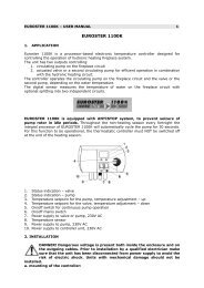
<strong>EUROSTER</strong> <strong>1100</strong>/<strong>1100</strong>C – USER MANUAL 1<br />
<strong>EUROSTER</strong> <strong>1100</strong>/<strong>1100</strong>C<br />
Congratulations on choosing our thermostatic controller <strong>EUROSTER</strong>. It is a technically<br />
advanced product which will serve you and your family for years bringing energy savings and<br />
thermal comfort.<br />
Prior to operating our thermostatic controller, please read this manual carefully.<br />
1. FUNCTION<br />
Euroster <strong>1100</strong> and Euroster <strong>1100</strong>C are electronic thermostatic controllers controlling the<br />
operation of circulation pumps in hydronic heating systems, according to the temperature<br />
settings.<br />
The function of the thermostatic controller/pump assembly is to cause forced circulation of<br />
water in hydronic heating systems supplied by coal or gas-fired boiler(s), which are not<br />
equipped with a pump control unit. The sensor of the thermostatic controller measures the<br />
heating water temperature on the inlet to the hydronic heating system.<br />
In a hydronic heating system supplied by a coal-fired boiler the thermostatic controller will<br />
switch off the pump upon flame failure. Pumping of water upon flame failure should be<br />
avoided, as suction caused by chimney draft will result in quicker lowering the temperature of<br />
water inside the boiler as compared to the radiators. The optimum temperature is preset on<br />
the controller’s scale (40ºC is the most common setting).<br />
In a hydronic heating systems supplied by a gas-fired boiler the temperature preset on the<br />
Euroster <strong>1100</strong>/ <strong>1100</strong>C must be lower than the temperature setting on the thermostatic<br />
controller fitted on the boiler. In order to avoid condensation on the surface of boiler during<br />
heating-up (so-called “sweating”) the temperature set with the knob should be above the dew<br />
point.<br />
<strong>EUROSTER</strong> <strong>1100</strong> C is equipped with ANTISTOP system, to prevent seizure of pump rotor in idle<br />
periods. Throughout the non-heating season every fortnight the integral processor of<br />
<strong>EUROSTER</strong> <strong>1100</strong> C will automatically cycle the pump for 30 seconds. For this function to be<br />
operational, the thermostatic controller must NOT be switched off at the end of the heating<br />
season.<br />
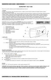
1. Power indication<br />
2. Pump status indication<br />
3. Power switch<br />
4. Continuous operation switch<br />
5. Temperature adjustment<br />
6. 230 V power supply cable<br />
7. Pump output cable<br />
8. Temperature sensor
<strong>EUROSTER</strong> <strong>1100</strong>/<strong>1100</strong>C – USER MANUAL 2<br />
2. INSTALLATION<br />
a) mounting of the thermostatic controller:<br />
− the thermostatic controller is mounted directly to wall or on a bracket with two screws<br />
(expansion plugs c/w screws are part of delivery)<br />
− for fixing the outgoing cables to the wall use cable clips<br />
b) mounting of the temperature sensor:<br />
− the sensor is not intended for immersion in liquids or installation in breechings/ flues<br />
− the temperature sensor should be installed on a bare outlet pipe from the boiler (as<br />
close to the boiler as possible)<br />
− for securing the sensor on the pipe use the supplied fixing clip<br />
− as a recommendation, the outlet pipe should be provided with thermal insulation on the<br />
section between the boiler and the temperature sensor<br />
IMPORTANT:<br />
If a central heating system is supplied from two sources: a coal-fired boiler and a gas-fired<br />
boiler, the temperature sensor should be mounted at the meeting point of the two outlet pipes<br />
and insulated.<br />
c) connection of power supply cable to terminals:<br />
− terminal ( ) - yellow or yellow and green (protective) conductor<br />
− terminal (N) - blue conductor<br />
− terminal (L) - brown conductor<br />
d) check-up of connections:<br />
− make sure that the connections have been made correctly and tighten the cover of the<br />
pump motor terminal box<br />
e) connection of thermostatic controller:<br />
− upon securing the cables against accidental pullout, connect the power supply cable<br />
to a 230V/50Hz grounding socket!<br />
IMPORTANT:<br />
Euroster <strong>1100</strong>/ <strong>1100</strong>C should be installed in a place with ambient temperature not exceeding<br />
40ºC.<br />
Danger! Hazardous voltage is present inside the enclosure. Any tampering with the<br />
unit may result in a life-threatening electrical injury!<br />
3. OPERATION<br />
After switching on the controller allow ca. 30 sec. for the controller to become fully<br />
operational<br />
a) switching on:<br />
− move the toggle switch (~) to position I<br />
− the green LED lights up.<br />
b) operation in the automatic mode:<br />
− move the right-hand toggle switch (►) to position 0<br />
− the pump is turned on and off depending on the temperature preset on the knob<br />
− the pump is turned on when the temperature measured by the sensor is higher than<br />
the preset temperature and it is turned off when the temperature has dropped below<br />
the setpoint.
<strong>EUROSTER</strong> <strong>1100</strong>/<strong>1100</strong>C – USER MANUAL 3<br />
c) continuous operation mode:<br />
− move the toggle switches (~) and (◄) to position I (both green LED and red LED are<br />
on)<br />
− the pump is running continuously irrespective of the setpoint and the ambient<br />
temperature measured by the sensor.<br />
4. DATA SHEET<br />
a. temperature setting range 25ºC – 55ºC<br />
b. hysteresis (turn on / turn off difference) ca. 5ºC<br />
c. supply voltage 230V AC<br />
d. rating of contacts 6A AC<br />
5. SHIPPING LIST<br />
a) controller and sensor 1 No.<br />
b) fixing clip 1 No.<br />
c) wall plugs 2 No.<br />
d) user manual 1 No.<br />
e) installation template 1 No.<br />
WIRING EXAMPLE<br />
It is a simplified diagram and does not show all the components necessary for fully functional<br />
operation of the system.<br />
Legend:<br />
1. gas-fired heating boiler<br />
2. coal-fired heating boiler<br />
2. shutoff valve<br />
3. strainer<br />
4. heating water circulating pump<br />
5. check valve<br />
6. heating unit – radiator<br />
7. temperature sensor<br />
8. central heating controller
<strong>EUROSTER</strong> <strong>1100</strong>/<strong>1100</strong>C – USER MANUAL 4<br />
Our products have been tested by the following certification bodies:<br />
*ELTEST - Centre for Evaluation, Research and Development of Electronic and Electrical<br />
Equipment – for conformity with the EMC Directive No. 89/336/EEC.<br />
Certified for compliance with the requirements of the following harmonised standards:<br />
PN-EN 60730-1:2002, PN-EN 60730-2-9:2000(U)<br />
PN-EN 55022:2000<br />
PN-EN 61000-4-2:1999+A2:2002(U)<br />
PN-EN 61000-4-3:2002<br />
PN-EN 61000-4-4:1999+A1:2001<br />
PN-EN 61000-4-5-1998+A1:2002(U)<br />
PN-EN 61000-4-6:1999+A1:2002<br />
PN-EN 61000-4-11:1997+A1:2002(U)<br />
*BBJ-SEP – Quality Testing Office – for compliance with the requirements of harmonised<br />
standards for the Low Voltage Directive (LVD) No. 73/23/EWG+93/68/EWG.<br />
Certified for compliance with the safety requirements of the following standards:<br />
PN-EN 60730-1:2002<br />
PN-EN 60730-2-9:2002