Miltronics 10139-DA420 User Manual Rev 2.5.pdf - Pacer Instruments
Miltronics 10139-DA420 User Manual Rev 2.5.pdf - Pacer Instruments
Miltronics 10139-DA420 User Manual Rev 2.5.pdf - Pacer Instruments

You also want an ePaper? Increase the reach of your titles
YUMPU automatically turns print PDFs into web optimized ePapers that Google loves.
By <strong>Miltronics</strong> Mfg., Inc. Phone: (603) 352-0187<br />
95 Krif Road Fax: (603) 352-1036<br />
Keene, NH 03431 USA sales@pacer-instruments-usa.com<br />
<br />
By <strong>Miltronics</strong> Mfg., Inc. Phone: (603) 352-0187<br />
95 Krif Road Fax: (603) 352-1036<br />
Keene, NH 03431 USA sales@pacer-instruments-usa.com<br />
<br />
<br />
Model <strong>DA420</strong><br />
THERMO-ANEMOMETER<br />
<br />
<strong>Miltronics</strong> Mfg. Svcs., Inc.<br />
95 Krif Road<br />
Keene, New Hampshire 03431<br />
USA<br />
(800) 283-1141<br />
(603) 352-0187<br />
Fax: (603) 352-1036<br />
sales@pacer-instruments-usa.com<br />
www.pacer-instruments-usa.com<br />
Copyright © 2013, <strong>Miltronics</strong> Mfg. Svcs., Inc.<br />
<strong>User</strong> <strong>Manual</strong><br />
<strong>DA420</strong> <strong>User</strong> <strong>Manual</strong>, PN <strong>10139</strong> <strong>Miltronics</strong> Mfg. Svcs., Inc.<br />
<strong>Rev</strong> 2.5, 04-Sept-2013 www.pacer-instruments-usa.com<br />
Copyright © 2013, <strong>Miltronics</strong> Mfg. Svcs., Inc. Page 24 of 24<br />
<strong>DA420</strong> <strong>User</strong> <strong>Manual</strong>, PN <strong>10139</strong> <strong>Miltronics</strong> Mfg. Svcs., Inc.<br />
<strong>Rev</strong> 2.5, 04-Sept-2013 www.pacer-instruments-usa.com<br />
Copyright © 2013, <strong>Miltronics</strong> Mfg. Svcs., Inc. Page 1 of 24
By <strong>Miltronics</strong> Mfg., Inc. Phone: (603) 352-0187<br />
95 Krif Road Fax: (603) 352-1036<br />
Keene, NH 03431 USA sales@pacer-instruments-usa.com<br />
<br />
By <strong>Miltronics</strong> Mfg., Inc. Phone: (603) 352-0187<br />
95 Krif Road Fax: (603) 352-1036<br />
Keene, NH 03431 USA sales@pacer-instruments-usa.com<br />
CALIBRATION<br />
INTRODUCTION<br />
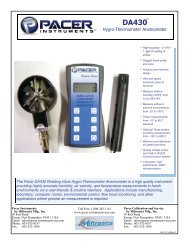
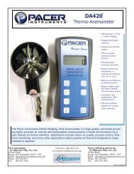
Congratulations on your purchase of a <strong>DA420</strong> Digital Thermo-Anemometer!<br />
You now own one of the most accurate, reliable, and highly regarded airflow<br />
measurement instruments available today.<br />
<strong>Pacer</strong>’s model <strong>DA420</strong> digital thermo-anemometer is a versatile instrument for<br />
measuring air velocity and temperature in various applications such as HVAC,<br />
aerospace development, industrial process airflow, and fluids research.<br />
The rugged yet precise probe can be used for airstreams that have a wide range<br />
of humidity, temperature and contaminants without compromising accuracy.<br />
Features include custom cable lengths, service temperatures up to 212˚F (100˚C)<br />
at the probe, high reliability, and long life.<br />
At the time of receipt, if more than 4 months has elapsed since the date of<br />
the original calibration, <strong>Miltronics</strong> will provide an initial complimentary<br />
calibration at the customer's request. If you elect to utilize this service,<br />
please include a copy of your dated proof of purchase and a copy of the<br />
original calibration certificate included with your unit. Call 603-352-0187<br />
and request a Service/Repair (SR) number prior to shipping your unit.<br />
To maintain your instrument in top working order, we recommend<br />
that you send it back to us for calibration each year, beginning one<br />
year after purchase.<br />
Our NIST-Traceable multi-point calibration services include<br />
ensuring the instrument performs within its accuracy tolerance,<br />
making any necessary adjustments, and inspecting all aspects of<br />
the instrument’s functionality so that you’ll have another year of<br />
dependable service. Calibration also includes a complimentary<br />
firmware upgrade so that you know you’ll have the latest advances<br />
in accuracy and reliability in your instrument.<br />
Additional points other than our standard calibration are also<br />
available from the factory. We can offer precise calibration<br />
tailored to your specific measurement needs using our state-of-theart<br />
facilities and calibration equipment.<br />
Please contact us or visit our website for the latest information on<br />
calibrating your instrument.<br />
<strong>DA420</strong> <strong>User</strong> <strong>Manual</strong>, PN <strong>10139</strong> <strong>Miltronics</strong> Mfg. Svcs., Inc.<br />
<strong>Rev</strong> 2.5, 04-Sept-2013 www.pacer-instruments-usa.com<br />
Copyright © 2013, <strong>Miltronics</strong> Mfg. Svcs., Inc. Page 2 of 24<br />
<strong>DA420</strong> <strong>User</strong> <strong>Manual</strong>, PN <strong>10139</strong> <strong>Miltronics</strong> Mfg. Svcs., Inc.<br />
<strong>Rev</strong> 2.5, 04-Sept-2013 www.pacer-instruments-usa.com<br />
Copyright © 2013, <strong>Miltronics</strong> Mfg. Svcs., Inc. Page 23 of 24
By <strong>Miltronics</strong> Mfg., Inc. Phone: (603) 352-0187<br />
95 Krif Road Fax: (603) 352-1036<br />
Keene, NH 03431 USA sales@pacer-instruments-usa.com<br />
<br />
By <strong>Miltronics</strong> Mfg., Inc. Phone: (603) 352-0187<br />
95 Krif Road Fax: (603) 352-1036<br />
Keene, NH 03431 USA sales@pacer-instruments-usa.com<br />
Exporting and Graphing Data<br />
Exporting serial port instrument data from the <strong>Pacer</strong> Instrument to a<br />
spreadsheet application such as Microsoft Excel or OpenOffice Calc<br />
allows the data to graphed or recorded.<br />
The simplest way to export the instrument data is to use a terminal<br />
emulator program, like Windows HyperTerminal, and either capture the<br />
serial data/text to a file (menu selection) or to manually highlight, copy,<br />
and then paste the instrument data into an editor such as Windows<br />
Notepad.<br />
Once you have the instrument data in a file, save the file as a .CSV type<br />
(e.g., InstrumentData.csv).<br />
Open the file in a spreadsheet application such as Microsoft Excel or<br />
OpenOffice Calc. A graph of the data as shown below can now be<br />
generated.<br />
Warranty<br />
This product is fully warranted against defective materials and/or<br />
workmanship for a period of one year after purchase, provided it was not<br />
improperly used. For your protection, please use this product as soon as<br />
possible. If returned, it must be securely wrapped, sent prepaid and insured<br />
to:<br />
<strong>Miltronics</strong> Mfg. Svcs., Inc.<br />
Attn: <strong>Pacer</strong> instruments<br />
95 Krif Road<br />
Keene, New Hampshire 03431<br />
USA<br />
Please include a note with name, address, telephone number and description<br />
of the problem. Although we provide assistance on <strong>Pacer</strong> products both<br />
personally and through our literature, it is still the total responsibility of the<br />
customer to determine the suitability of the product for use in their<br />
application.<br />
This manual is provided by <strong>Miltronics</strong> Mfg. Svcs., Inc. without any kind of<br />
warranty. Precautions have been taken in accurately preparing this manual;<br />
however, we neither assume responsibility for any omissions or errors that<br />
may appear nor assume liability for any damages that result from the use of<br />
the products in accordance with the information contained in the manual.<br />
<strong>DA420</strong> <strong>User</strong> <strong>Manual</strong>, PN <strong>10139</strong> <strong>Miltronics</strong> Mfg. Svcs., Inc.<br />
<strong>Rev</strong> 2.5, 04-Sept-2013 www.pacer-instruments-usa.com<br />
Copyright © 2013, <strong>Miltronics</strong> Mfg. Svcs., Inc. Page 22 of 24<br />
<strong>DA420</strong> <strong>User</strong> <strong>Manual</strong>, PN <strong>10139</strong> <strong>Miltronics</strong> Mfg. Svcs., Inc.<br />
<strong>Rev</strong> 2.5, 04-Sept-2013 www.pacer-instruments-usa.com<br />
Copyright © 2013, <strong>Miltronics</strong> Mfg. Svcs., Inc. Page 3 of 24
By <strong>Miltronics</strong> Mfg., Inc. Phone: (603) 352-0187<br />
95 Krif Road Fax: (603) 352-1036<br />
Keene, NH 03431 USA sales@pacer-instruments-usa.com<br />
SECTION 1 - SPECIFICATIONS<br />
Ranges:<br />
Probe APT275 Airflow:<br />
50 to 7800 ft/min (feet per minute)<br />
0.2 to 40.00 m/sec (meters per second)<br />
Air Probe APT100: 300 to 6890 ft/min (1.5 to 35.00 m/sec)<br />
Temperature: (using either air velocity probe): -4° to 212°F<br />
(-20° to 100°C)<br />
<br />
By <strong>Miltronics</strong> Mfg., Inc. Phone: (603) 352-0187<br />
95 Krif Road Fax: (603) 352-1036<br />
Keene, NH 03431 USA sales@pacer-instruments-usa.com<br />
Serial Port Settings<br />
Bits per Second (Baud) 9600<br />
Data bit 8<br />
Parity<br />
None<br />
Stop bits 1<br />
Flow Control<br />
None<br />
Serial Port Protocol<br />
Data Output Interval One Second<br />
Data Format<br />
Comma-Separated Values (CSV)<br />
Measurement Units Same as Units shown on LCD Display<br />
Airflow Accuracy: APT275: ±1.0% of reading ±1 digit<br />
APT100: ±0.5% full scale ±0.75% of reading<br />
Temperature Accuracy: ±(0.3°C + 0.2% of reading in °C)<br />
Temperature accuracy examples: ±0.3°C at 20°C<br />
±0.5°F at 68°F<br />
Resolution:<br />
Air Velocity:<br />
Temperature:<br />
Operating Temperature:<br />
Instrument:<br />
Air Probes:<br />
Power Supply:<br />
Battery Life:<br />
1 ft/min or 0.01 m/sec<br />
0.1˚F or 0.1˚C<br />
32˚ to 125˚F (0˚ to 50˚C)<br />
-4˚ to 212˚F (-20˚ to 100˚C)<br />
3 AA alkaline batteries<br />
Approx. 150 hours, without backlight<br />
Battery check: Automatic low battery display<br />
Display:<br />
0.5” LCD, 4 digits, with LED backlight<br />
Below are examples of the formatted output data for <strong>Pacer</strong>’s Premier<br />
Series <strong>Instruments</strong> (units may be different depending on the units<br />
selected on the LCD display):<br />
Model DA400:<br />
Air,47,FPM <br />
Model DA410 displaying in Air Velocity Mode: Air,47,FPM <br />
Model DA410 displaying in Volume Flow Mode: Air,251,CFM <br />
Model <strong>DA420</strong>:<br />
Model DA430:<br />
Model DH500:<br />
Air,47,FPM <br />
Air,47,FPM <br />
NOTE: Units with USB or RS232 communications, output only Air<br />
data at this time. Temperature data is not available on the output.<br />
<strong>DA420</strong> <strong>User</strong> <strong>Manual</strong>, PN <strong>10139</strong> <strong>Miltronics</strong> Mfg. Svcs., Inc.<br />
<strong>Rev</strong> 2.5, 04-Sept-2013 www.pacer-instruments-usa.com<br />
Copyright © 2013, <strong>Miltronics</strong> Mfg. Svcs., Inc. Page 4 of 24<br />
<strong>DA420</strong> <strong>User</strong> <strong>Manual</strong>, PN <strong>10139</strong> <strong>Miltronics</strong> Mfg. Svcs., Inc.<br />
<strong>Rev</strong> 2.5, 04-Sept-2013 www.pacer-instruments-usa.com<br />
Copyright © 2013, <strong>Miltronics</strong> Mfg. Svcs., Inc. Page 21 of 24
By <strong>Miltronics</strong> Mfg., Inc. Phone: (603) 352-0187<br />
95 Krif Road Fax: (603) 352-1036<br />
Keene, NH 03431 USA sales@pacer-instruments-usa.com<br />
<br />
By <strong>Miltronics</strong> Mfg., Inc. Phone: (603) 352-0187<br />
95 Krif Road Fax: (603) 352-1036<br />
Keene, NH 03431 USA sales@pacer-instruments-usa.com<br />
Make sure that “Append line feeds to incoming line ends” is CHECKED<br />
as shown below. Click OK. Options Available:<br />
Protective Boot and Splash-Proof Seal for the Instrument<br />
USB Communications<br />
RS232 Communications<br />
Analog 0-5 Volt Output<br />
Additional Probes, APT275 or APT100<br />
Extra extension and/or flexible rods<br />
Custom cable lengths<br />
You will now receive data from your instrument. The graphic below<br />
shows the serial port output data from Windows HyperTerminal when<br />
connected to a <strong>Pacer</strong> DA400 Instrument.<br />
Included:<br />
<br />
<br />
<br />
<br />
<br />
<br />
<br />
<br />
(1) <strong>DA420</strong> Instrument<br />
(1) Vane-type probe head with RTD temperature sensor, choice of<br />
APT100 or APT275<br />
(3) Rigid extension rods with handle grip<br />
(1) Flexible extension rod<br />
(1) Probe connection cable, 5 ft.<br />
(3) Size AA 1.5V alkaline batteries<br />
(1) Hard-shell carrying case with foam liner<br />
(1) <strong>DA420</strong> operation manual<br />
INSTRUMENT<br />
Dimensions<br />
<strong>DA420</strong> <strong>User</strong> <strong>Manual</strong>, PN <strong>10139</strong> <strong>Miltronics</strong> Mfg. Svcs., Inc.<br />
<strong>Rev</strong> 2.5, 04-Sept-2013 www.pacer-instruments-usa.com<br />
Copyright © 2013, <strong>Miltronics</strong> Mfg. Svcs., Inc. Page 20 of 24<br />
<strong>DA420</strong> <strong>User</strong> <strong>Manual</strong>, PN <strong>10139</strong> <strong>Miltronics</strong> Mfg. Svcs., Inc.<br />
<strong>Rev</strong> 2.5, 04-Sept-2013 www.pacer-instruments-usa.com<br />
Copyright © 2013, <strong>Miltronics</strong> Mfg. Svcs., Inc. Page 5 of 24
By <strong>Miltronics</strong> Mfg., Inc. Phone: (603) 352-0187<br />
95 Krif Road Fax: (603) 352-1036<br />
Keene, NH 03431 USA sales@pacer-instruments-usa.com<br />
<br />
By <strong>Miltronics</strong> Mfg., Inc. Phone: (603) 352-0187<br />
95 Krif Road Fax: (603) 352-1036<br />
Keene, NH 03431 USA sales@pacer-instruments-usa.com<br />
APT275 PROBE<br />
Click on File → Properties. You will see the window shown below. Click<br />
on the Settings tab and then click on ASCII Setup… as shown below.<br />
<strong>DA420</strong> <strong>User</strong> <strong>Manual</strong>, PN <strong>10139</strong> <strong>Miltronics</strong> Mfg. Svcs., Inc.<br />
<strong>Rev</strong> 2.5, 04-Sept-2013 www.pacer-instruments-usa.com<br />
Copyright © 2013, <strong>Miltronics</strong> Mfg. Svcs., Inc. Page 6 of 24<br />
<strong>DA420</strong> <strong>User</strong> <strong>Manual</strong>, PN <strong>10139</strong> <strong>Miltronics</strong> Mfg. Svcs., Inc.<br />
<strong>Rev</strong> 2.5, 04-Sept-2013 www.pacer-instruments-usa.com<br />
Copyright © 2013, <strong>Miltronics</strong> Mfg. Svcs., Inc. Page 19 of 24
By <strong>Miltronics</strong> Mfg., Inc. Phone: (603) 352-0187<br />
95 Krif Road Fax: (603) 352-1036<br />
Keene, NH 03431 USA sales@pacer-instruments-usa.com<br />
<br />
By <strong>Miltronics</strong> Mfg., Inc. Phone: (603) 352-0187<br />
95 Krif Road Fax: (603) 352-1036<br />
Keene, NH 03431 USA sales@pacer-instruments-usa.com<br />
APT100 PROBE<br />
SECTION 2 – SWITCH FUNCTIONS<br />
Click OK.<br />
On the next window, next to “Connect using,” select the COM port you<br />
that you are using with your instrument. Click OK.<br />
In the next window, select the port settings as shown below and click<br />
OK. (The Serial Port settings are also listed at the end of this section).<br />
Pressing the ON/OFF key switches the instrument ON. Hold down the<br />
key for 2 seconds to switch the unit OFF. The unit will automatically<br />
power off after 30 minutes without any key presses. To disable auto<br />
power-off, hold down the power button during turn-on. The unit will<br />
<strong>DA420</strong> <strong>User</strong> <strong>Manual</strong>, PN <strong>10139</strong> <strong>Miltronics</strong> Mfg. Svcs., Inc.<br />
<strong>Rev</strong> 2.5, 04-Sept-2013 www.pacer-instruments-usa.com<br />
Copyright © 2013, <strong>Miltronics</strong> Mfg. Svcs., Inc. Page 18 of 24<br />
<strong>DA420</strong> <strong>User</strong> <strong>Manual</strong>, PN <strong>10139</strong> <strong>Miltronics</strong> Mfg. Svcs., Inc.<br />
<strong>Rev</strong> 2.5, 04-Sept-2013 www.pacer-instruments-usa.com<br />
Copyright © 2013, <strong>Miltronics</strong> Mfg. Svcs., Inc. Page 7 of 24
By <strong>Miltronics</strong> Mfg., Inc. Phone: (603) 352-0187<br />
95 Krif Road Fax: (603) 352-1036<br />
Keene, NH 03431 USA sales@pacer-instruments-usa.com<br />
flash AOFF, which means that the auto power-off has been disabled.<br />
The auto power-off is re-enabled each time the instrument is turned on.<br />
Press the BACKLIGHT key to turn the LCD backlight on for 30<br />
seconds. To turn the backlight on permanently, hold the backlight key<br />
down for 3 seconds. The LCD will flash. The backlight is now<br />
switched on permanently. To switch the backlight off, press the backlight key<br />
again.<br />
<br />
By <strong>Miltronics</strong> Mfg., Inc. Phone: (603) 352-0187<br />
95 Krif Road Fax: (603) 352-1036<br />
Keene, NH 03431 USA sales@pacer-instruments-usa.com<br />
this once). For Windows users, open the Windows Device<br />
Manager (found in Control Panel) and verify that a serial port<br />
exists.<br />
You are now ready to capture the data being measured by<br />
your instrument.<br />
Please refer to Appendix G – Viewing and Capturing Data<br />
for further instructions.<br />
Press the TEMPERATURE key to display the current temperature of<br />
the air stream as measured by the Air Probe. To switch the units<br />
between degrees Fahrenheit (°F) and degrees Celsius (°C), press<br />
the TEMPERATURE key again. Either °C or °F will be displayed along with<br />
the reading.<br />
Press the FPM/MPS key to display the current air velocity as measured<br />
by the air probe. To switch the measurement units from FPM (feet per<br />
minute, 1 FPM resolution) to MPS (meters per second, 0.01 MPS<br />
resolution), press the FPM/MPS key again. Either FPM or MPS will be<br />
displayed along with the reading.<br />
Press the SAMPLE RATE key to change the measurement averaging<br />
rate (“sample rate”) of the instrument for air velocity only.<br />
An average value of airspeed measurements during the<br />
preceding 2 seconds is displayed.<br />
An average value of airspeed measurements during the<br />
preceding 4 seconds is displayed.<br />
<br />
An average value of airspeed measurements during the<br />
preceding 8 seconds is displayed.<br />
<strong>DA420</strong> <strong>User</strong> <strong>Manual</strong>, PN <strong>10139</strong> <strong>Miltronics</strong> Mfg. Svcs., Inc.<br />
<strong>Rev</strong> 2.5, 04-Sept-2013 www.pacer-instruments-usa.com<br />
Copyright © 2013, <strong>Miltronics</strong> Mfg. Svcs., Inc. Page 8 of 24<br />
APPENDIX G – VIEWING AND CAPTURING DATA<br />
(IF EQUIPPED WITH EITHER USB OR RS232 OUTPUTS)<br />
There are many ways to capture the serial port data from the <strong>Pacer</strong><br />
Instrument. The simplest method is to use a terminal emulator program.<br />
Using a terminal emulator allows the serial COM port to be opened, with<br />
the above port settings, and real-time data to be viewed from the<br />
instrument. One such terminal emulator program is Windows<br />
HyperTerminal.<br />
To launch Windows HyperTerminal, go to:<br />
START → All Programs → Accessories → Communications →<br />
HyperTerminal<br />
Enter a name for the Connection, such as “<strong>Pacer</strong> DA400” and choose an<br />
icon.<br />
<strong>DA420</strong> <strong>User</strong> <strong>Manual</strong>, PN <strong>10139</strong> <strong>Miltronics</strong> Mfg. Svcs., Inc.<br />
<strong>Rev</strong> 2.5, 04-Sept-2013 www.pacer-instruments-usa.com<br />
Copyright © 2013, <strong>Miltronics</strong> Mfg. Svcs., Inc. Page 17 of 24
By <strong>Miltronics</strong> Mfg., Inc. Phone: (603) 352-0187<br />
95 Krif Road Fax: (603) 352-1036<br />
Keene, NH 03431 USA sales@pacer-instruments-usa.com<br />
<br />
By <strong>Miltronics</strong> Mfg., Inc. Phone: (603) 352-0187<br />
95 Krif Road Fax: (603) 352-1036<br />
Keene, NH 03431 USA sales@pacer-instruments-usa.com<br />
You are now ready to capture the data being measured by<br />
your instrument.<br />
<br />
An average value of airspeed measurements during the<br />
preceding 16 seconds is displayed.<br />
Please refer to Appendix G – Viewing and Capturing Data<br />
for further instructions.<br />
Note: The sample rate for temperature readings is always 2 seconds.<br />
NOTE: Units with USB or RS232 communications, output only Air<br />
data at this time. Temperature data is not available on the output.<br />
APPENDIX F – RS232 COMMUNICATIONS (IF EQUIPPED)<br />
If the instrument is equipped with the RS232 Communications option,<br />
there will be a three pin male connector on the bottom of the instrument.<br />
Also, an RS232 cable will be included with the instrument. This cable<br />
will have a three pin female connector on one end and a DB9 Female<br />
connector on the other end.<br />
RS232 Data Output – Instructions for Use<br />
STEP 1: Connect the RS232 cable (included) to the female connector<br />
on the bottom of your instrument. Connect the other end to an<br />
RS232 port on your computer.<br />
Press the MAX/MIN key to record and display the maximum reading<br />
for either temperature or air velocity. The maximum reading display<br />
will alternate with the letter “H” displayed with the sample rate. Press<br />
the MAX/MIN key again to record and hold the minimum reading.<br />
The minimum reading display will alternate with the letter “L” displayed with<br />
the sample rate.<br />
For example:<br />
alternating with signifies that 1065 is the highest airspeed<br />
reading since the MAX/MIN key was pressed, and the sample rate is set to 8<br />
seconds.<br />
alternating with signifies that 82 is the lowest airspeed<br />
reading since the MAX/MIN key was pressed, and the sample rate is set to 16<br />
seconds.<br />
To exit MAX/MIN mode, press the SAMPLE RATE key.<br />
STEP 3: Turn the Instrument ON.<br />
STEP 4: Verify that the Instrument has been set up as a RS232 Serial<br />
Port with a unique COM port number. (You only need to do<br />
<strong>DA420</strong> <strong>User</strong> <strong>Manual</strong>, PN <strong>10139</strong> <strong>Miltronics</strong> Mfg. Svcs., Inc.<br />
<strong>Rev</strong> 2.5, 04-Sept-2013 www.pacer-instruments-usa.com<br />
Copyright © 2013, <strong>Miltronics</strong> Mfg. Svcs., Inc. Page 16 of 24<br />
<strong>DA420</strong> <strong>User</strong> <strong>Manual</strong>, PN <strong>10139</strong> <strong>Miltronics</strong> Mfg. Svcs., Inc.<br />
<strong>Rev</strong> 2.5, 04-Sept-2013 www.pacer-instruments-usa.com<br />
Copyright © 2013, <strong>Miltronics</strong> Mfg. Svcs., Inc. Page 9 of 24
By <strong>Miltronics</strong> Mfg., Inc. Phone: (603) 352-0187<br />
95 Krif Road Fax: (603) 352-1036<br />
Keene, NH 03431 USA sales@pacer-instruments-usa.com<br />
Press the HOLD/RESET key to freeze the current reading on the display.<br />
HOLD is displayed on the LCD and the reading is held.<br />
Press the HOLD/RESET key a second time to clear this mode and return the unit<br />
to normal operation.<br />
Press the HOLD/RESET key while in MIN/MAX mode to display BOTH the<br />
minimum and maximum readings since the MAX/MIN key was pressed. Once<br />
the HOLD/RESET key is pressed while in MAX/MIN mode, new readings are<br />
no longer recorded. To return to MAX/MIN mode, press the HOLD/RESET<br />
key again.<br />
APPENDIX A – LCD DISPLAY SYMBOLS<br />
<br />
By <strong>Miltronics</strong> Mfg., Inc. Phone: (603) 352-0187<br />
95 Krif Road Fax: (603) 352-1036<br />
Keene, NH 03431 USA sales@pacer-instruments-usa.com<br />
We recommend downloading the setup executable, which<br />
automatically runs and configures the drivers for you.<br />
STEP 2: Connect the USB cable (included) to the male connector on<br />
the bottom of your instrument. Connect the other end to a<br />
USB port on your computer.<br />
STEP 3: Turn the Instrument ON.<br />
STEP 4: Verify that the Instrument has been set up as a USB Serial<br />
Port with a unique COM port number. (You only need to do<br />
this once)<br />
For Windows users, open the Windows Device Manager<br />
(found in Control Panel) and verify that a USB serial port exists<br />
as shown below.<br />
APPENDIX B – BATTERY REPLACEMENT<br />
<strong>DA420</strong> <strong>User</strong> <strong>Manual</strong>, PN <strong>10139</strong> <strong>Miltronics</strong> Mfg. Svcs., Inc.<br />
<strong>Rev</strong> 2.5, 04-Sept-2013 www.pacer-instruments-usa.com<br />
Copyright © 2013, <strong>Miltronics</strong> Mfg. Svcs., Inc. Page 10 of 24<br />
<strong>DA420</strong> <strong>User</strong> <strong>Manual</strong>, PN <strong>10139</strong> <strong>Miltronics</strong> Mfg. Svcs., Inc.<br />
<strong>Rev</strong> 2.5, 04-Sept-2013 www.pacer-instruments-usa.com<br />
Copyright © 2013, <strong>Miltronics</strong> Mfg. Svcs., Inc. Page 15 of 24
By <strong>Miltronics</strong> Mfg., Inc. Phone: (603) 352-0187<br />
95 Krif Road Fax: (603) 352-1036<br />
Keene, NH 03431 USA sales@pacer-instruments-usa.com<br />
<br />
By <strong>Miltronics</strong> Mfg., Inc. Phone: (603) 352-0187<br />
95 Krif Road Fax: (603) 352-1036<br />
Keene, NH 03431 USA sales@pacer-instruments-usa.com<br />
Mating Cable Connector:<br />
Binder Part No. 99-0413-00-05<br />
APPENDIX C – AIRFLOW VOLUME CALCULATIONS<br />
APPENDIX E - USB DATA OUTPUT (IF EQUIPPED)<br />
If the instrument is equipped with the USB Communications option, there<br />
will be a four pin male connector on the bottom of the instrument. Also, a<br />
USB cable will be included with the instrument. This cable will have a<br />
four pin female connector on one end and a USB Type-A connector on<br />
the other end.<br />
To calculate cubic feet per minute (CFM) from a measured air velocity (FPM),<br />
you need the calculated cross-sectional area of the air flow stream:<br />
Volume Flow (CFM) = Velocity (FPM) X Area (sq ft).<br />
In a rectangular duct this cross sectional area equals the Width times the Height.<br />
USB Data Output – Instructions for Use<br />
STEP 1: Install a Virtual COM Port (VCP) Driver on your computer.<br />
Free VCP drivers can be downloaded for Windows, Linux, and<br />
MAC from FTDI Ltd on their website:<br />
http://www.ftdichip.com/Drivers/VCP.htm<br />
W x H=A (cross-sectional area)<br />
In a circular duct this cross section area equals the radius squared times π (3.14).<br />
<strong>DA420</strong> <strong>User</strong> <strong>Manual</strong>, PN <strong>10139</strong> <strong>Miltronics</strong> Mfg. Svcs., Inc.<br />
<strong>Rev</strong> 2.5, 04-Sept-2013 www.pacer-instruments-usa.com<br />
Copyright © 2013, <strong>Miltronics</strong> Mfg. Svcs., Inc. Page 14 of 24<br />
<strong>DA420</strong> <strong>User</strong> <strong>Manual</strong>, PN <strong>10139</strong> <strong>Miltronics</strong> Mfg. Svcs., Inc.<br />
<strong>Rev</strong> 2.5, 04-Sept-2013 www.pacer-instruments-usa.com<br />
Copyright © 2013, <strong>Miltronics</strong> Mfg. Svcs., Inc. Page 11 of 24
By <strong>Miltronics</strong> Mfg., Inc. Phone: (603) 352-0187<br />
95 Krif Road Fax: (603) 352-1036<br />
Keene, NH 03431 USA sales@pacer-instruments-usa.com<br />
<br />
By <strong>Miltronics</strong> Mfg., Inc. Phone: (603) 352-0187<br />
95 Krif Road Fax: (603) 352-1036<br />
Keene, NH 03431 USA sales@pacer-instruments-usa.com<br />
GRY 3 --- Not Used --- --- N/A --- --- N/A --- --- N/A ---<br />
WHT 4 Temperature 0 to 5 Volts -20°C to 80°C Temperature [°C] = 20×V - 20<br />
R x R x 3.14=A (cross-sectional area)<br />
To convert an area calculated in square inches to an area calculated in square<br />
feet (which is required for the Volume Flow equation above) divide by 144:<br />
(area in sq in.)/144 = (area in sq ft.).<br />
Example: The air duct is rectangular, the width is 24 in. and the height is<br />
12 in. The air velocity reading through the duct is 450 FPM.<br />
Calculate the Volume Flow.<br />
*To convert from Volts to Air Velocity in Feet per Minute, multiply by 2000.<br />
► For example, an analog output of 2.375 Volts on the green wire means that<br />
the instrument is measuring an air velocity of 4750 feet per minute (FPM).<br />
► 2.375 Volts × 2000 = 4750 FPM<br />
*To convert from Volts to Temperature in degrees Celsius (°C), multiply by 20<br />
and subtract 20.<br />
► For example, an analog output of 3.458 Volts on the white wire means that<br />
the instrument is measuring a temperature of 49.16 °C.<br />
► 3.458 Volts × 20 – 20 = 49.16 °C<br />
Step 1: Cross-sectional area = 24 in. x 12 in. = 288 sq in.<br />
Step 2: 288 sq in /144 = 2 sq ft.<br />
Step 3: Volume flow = Air Velocity x Area, therefore,<br />
Volume flow rate = 450 FPM x 2 sq ft. = 900 CFM.<br />
APPENDIX D – ANALOG OUTPUTS (IF EQUIPPED)<br />
If the instrument is equipped with the analog output option, there will be a fivepin<br />
connector on the bottom of the instrument. Also, an analog output cable will<br />
be included with the instrument. This cable will have a five-pin connector on<br />
one end and four tinned wires on the other end.<br />
The instrument will output a Voltage between 0 and 5 Volts that corresponds to<br />
the Air Velocity and Temperature measured by the instrument. The output<br />
range, pin assignments, and wire colors are given in the table below. Also<br />
shown is a block diagram of the analog output circuit.<br />
Corresponding<br />
Wire Analog Output Measurement Equation* to convert from<br />
Color Pin # Function Voltage Range Range Volts (V) to Measurement Value<br />
BLK 1 Ground --- N/A --- --- N/A --- --- N/A ---<br />
GRN 2 Air Velocity 0 to 5 Volts 0 to 10,000 FPM Air Velocity = 2000×V<br />
Note: When using analog outputs, there is an additional ±1% error in the<br />
analog output voltage. This is in addition to the normal measurement error.<br />
► For example, an air velocity reading of 500 FPM would normally have an<br />
accuracy of ±1% of reading ±1 digit (±6 FPM) when the data is viewed<br />
on the LCD display.<br />
► With the additional error associated with the analog output voltage, the<br />
effective accuracy of the analog output for this air velocity measurement<br />
will be ±2% of reading ±1 digit (±11 FPM).<br />
Custom Analog Voltage Outputs are also available – contact <strong>Pacer</strong> for details.<br />
Analog Output circuit block diagram and connector pin assignment<br />
<strong>DA420</strong> <strong>User</strong> <strong>Manual</strong>, PN <strong>10139</strong> <strong>Miltronics</strong> Mfg. Svcs., Inc.<br />
<strong>Rev</strong> 2.5, 04-Sept-2013 www.pacer-instruments-usa.com<br />
Copyright © 2013, <strong>Miltronics</strong> Mfg. Svcs., Inc. Page 12 of 24<br />
<strong>DA420</strong> <strong>User</strong> <strong>Manual</strong>, PN <strong>10139</strong> <strong>Miltronics</strong> Mfg. Svcs., Inc.<br />
<strong>Rev</strong> 2.5, 04-Sept-2013 www.pacer-instruments-usa.com<br />
Copyright © 2013, <strong>Miltronics</strong> Mfg. Svcs., Inc. Page 13 of 24