Pacer DA40 User Manual - Pacer Instruments
Pacer DA40 User Manual - Pacer Instruments
Pacer DA40 User Manual - Pacer Instruments

Create successful ePaper yourself
Turn your PDF publications into a flip-book with our unique Google optimized e-Paper software.
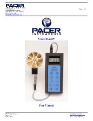
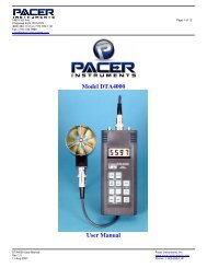
TM95 Krif Road Page 12 of 12Keene, NH 03431(800) 283-1141 or (800) 828-9089 Fax: (603) 352-4444 or (603-352-1036)sales@pacer-instruments-usa.com or sales@miltronics.comTM95 Krif Road Page 1 of 12Keene, NH 03431(800) 283-1141 or (800) 828-9089 Fax: (603) 352-4444 or (603-352-1036)sales@pacer-instruments-usa.com or sales@miltronics.comMiltronics Mfg., Inc.95 Krif RoadKeene, New Hampshire 03431USA(800) 283-1141(603) 352-0187Fax: (603) 352-1036sales@miltronics.comModel THT500www.miltronics.comwww.pacer-instruments-usa.comCopyright © 2009-2013, Miltronics Mfg., Inc.Miltronics, AT400, TAT420, THT500 and theMiltronics Mfg., Inc. logo are trademarks of Miltronics Mfg., Inc.<strong>User</strong> <strong>Manual</strong>THT500 <strong>User</strong> <strong>Manual</strong> Miltronics Mfg. Svcs., Inc.Rev 1.2 www.pacer-instruments-usa.com06-Sept-2013 www.miltronics.comTHT500 <strong>User</strong> <strong>Manual</strong> Miltronics Mfg. Svcs., Inc.Rev 1.2 www.pacer-instruments-usa.com06-Sept-2013 www.miltronics.com
TM95 Krif Road Page 2 of 12Keene, NH 03431(800) 283-1141 or (800) 828-9089 Fax: (603) 352-4444 or (603-352-1036)sales@pacer-instruments-usa.com or sales@miltronics.comTM95 Krif Road Page 11 of 12Keene, NH 03431(800) 283-1141 or (800) 828-9089 Fax: (603) 352-4444 or (603-352-1036)sales@pacer-instruments-usa.com or sales@miltronics.comNotes:WarrantyThis product is fully warranted against defective materialsand/or workmanship for a period of one year after purchase,provided it was not improperly used. For your protection,please use this product as soon as possible. If returned, it mustbe securely wrapped, sent prepaid and insured to:Miltronics Mfg., Inc.95 Krif RoadKeene, NH 03431PH: 603-352-3333FX: 603-352-4444Please include a note with name, address, telephone numberand description of the problem. Although we provideassistance on <strong>Pacer</strong> <strong>Instruments</strong> & Miltronics products bothpersonally and through our literature, it is still the totalresponsibility of the customer to determine the suitability of theproduct for use in their application.This manual is provided by Miltronics Mfg., Inc. without anykind of warranty. Precautions have been taken in accuratelypreparing this manual; however, we neither assumeresponsibility for any omissions or errors that may appear norassume liability for any damages that result from the use of theproducts in accordance with the information contained in themanual.THT500 <strong>User</strong> <strong>Manual</strong> Miltronics Mfg. Svcs., Inc.Rev 1.2 www.pacer-instruments-usa.com06-Sept-2013 www.miltronics.comTHT500 <strong>User</strong> <strong>Manual</strong> Miltronics Mfg. Svcs., Inc.Rev 1.2 www.pacer-instruments-usa.com06-Sept-2013 www.miltronics.com
TM95 Krif Road Page 10 of 12Keene, NH 03431(800) 283-1141 or (800) 828-9089 Fax: (603) 352-4444 or (603-352-1036)sales@pacer-instruments-usa.com or sales@miltronics.comTM95 Krif Road Page 3 of 12Keene, NH 03431(800) 283-1141 or (800) 828-9089 Fax: (603) 352-4444 or (603-352-1036)sales@pacer-instruments-usa.com or sales@miltronics.comNotes:INTRODUCTIONThe THT500 humidity-temperature transmitters supply accuratehumidity and temperature (THT500) data from a room or processair source on a continuous basis to a computer, chart recorder,printer, meter or control circuit.The AT400 and TAT420 air velocity transmitters supply accurateair velocity and (TAT420) temperature data from a building orprocess airflow on a continuous basis to a computer, chartrecorder, printer, and meter or control circuit.Every instrument has terminals for both DC and AC power, and0-1V, 0-5V and 4-20mA outputs. The outputs are concurrent andcan accept multiple wires (depending on the gauge used).The humidity or humidity-temperature probe can be mounted onthe instrument enclosure or at a remote location; that choice mustbe made at the time of purchase. The probe can be fitted with aoptional sintered-metal filter for dusty or harsh environments.THT500 <strong>User</strong> <strong>Manual</strong> Miltronics Mfg. Svcs., Inc.Rev 1.2 www.pacer-instruments-usa.com06-Sept-2013 www.miltronics.comTHT500 <strong>User</strong> <strong>Manual</strong> Miltronics Mfg. Svcs., Inc.Rev 1.2 www.pacer-instruments-usa.com06-Sept-2013 www.miltronics.com
TM95 Krif Road Page 4 of 12Keene, NH 03431(800) 283-1141 or (800) 828-9089 Fax: (603) 352-4444 or (603-352-1036)sales@pacer-instruments-usa.com or sales@miltronics.comSPECIFICATIONSSensors:Humidity sensor:Temperature:Range:Relative Humidity:Temperature:Accuracy:Relative Humidity:Temperature:Resolution (optional display):Relative Humidity:Temperature:Response Time:Relative Humidity:Capacitive (Thin Film)PT100 RTD5% to 95% RH-4˚ to 176˚F (-20˚ to 80˚C)±2% RH±0.5˚C0.1%RH0.1˚F or ˚C90% of final value in 15 sec.Approximately 60 secondsTemperature:Analog Outputs (separate and concurrent):Relative Humidity:0-1V, 0-5V and 4-20mA represent 0-100%RHTemperature:0-1V, 0-5V and 4-20mA represent -4 to 176˚F (-20 to 80˚C)Operating Range:Power Supply:-4˚ to 176˚F (-20˚ to 80˚C)120 or 220VAC, 50-60Hz, also10-30 VDCInput Current (with all options):10-30VDC:38mA110VAC:18mA220VAC:9mAOutput Impedance (0-1V and 0-5V outputs): 1KΩEnclosure: ABS plastic, NEMA Class 4TM95 Krif Road Page 9 of 12Keene, NH 03431(800) 283-1141 or (800) 828-9089 Fax: (603) 352-4444 or (603-352-1036)sales@pacer-instruments-usa.com or sales@miltronics.com_____________________________1 In order to insure the proper calibration, all custom-length cablesfor the THT500 must be ordered at the time the transmitter ispurchased; or the unit must be returned for calibration.2 The maximum length for probe cables is 150 ft.; please consultmanufacturer if longer cable is required.3 Cable grips will seal on round cables from 2.5 to 6.5mm diameter.For wire bundles, if you wish to insure water tightness, use RTVsilicon or other sealant safe for electronics at end of cable grip.Notes:Dimensions:Housing: 4.8” x 4.8” x 2.2”Probe:4.5” x 1” diameterWeight:18 ouncesOptions:Sintered-metal filter: Harsh environmentsTHT500 <strong>User</strong> <strong>Manual</strong> Miltronics Mfg. Svcs., Inc.Rev 1.2 www.pacer-instruments-usa.com06-Sept-2013 www.miltronics.comTHT500 <strong>User</strong> <strong>Manual</strong> Miltronics Mfg. Svcs., Inc.Rev 1.2 www.pacer-instruments-usa.com06-Sept-2013 www.miltronics.com
TM95 Krif Road Page 8 of 12Keene, NH 03431(800) 283-1141 or (800) 828-9089 Fax: (603) 352-4444 or (603-352-1036)sales@pacer-instruments-usa.com or sales@miltronics.comAPPENDIX A – No Longer AvailableAPPENDIX B – Collecting data by means of resident “Hyper-Terminal” program on Win 95, 98, NT4, and Win 2000 PC’sA. Set up Communication Port.1) Find and open “HyperTerminal” under “Accessories” and“Communications”2) Type a name like “Humidity Transmitter” and select anicon, then click “OK”3) In the “Connect using:” box, select a COM port - probably“COM 1”. Click “OK”B. Set up “COM 1 Properties”1) Set “Bits per second:” to “1200”2) Set “Data bits:” to “8”3) Set “Parity:” to “None”4) Set “Stop bits:” to “1”5) Set “Flow control:” to “None”6) Click “OK”, the select “Save”C. Connect cable and transfer data1) Connect the RS-232 cable to “COM 1” port2) Power up transmitter3) Select “Call” from “Call” menu. Data will fill window4) To stop, select “Disconnect” from “Call” menu5) To save data, select “Save As…” and give file a nameD. To transfer to Excel1) Select data file from C5 above and open with “Notepad”2) Select data to be transferred and “Copy”3) Open a new blank Excel worksheet, select “Paste”4) Select entire Column “A”. Under “Data” menu, select“Text to columns…” and click “Next”5) Follow directions to separate data, then click “Finish”THT500 <strong>User</strong> <strong>Manual</strong> Miltronics Mfg. Svcs., Inc.Rev 1.2 www.pacer-instruments-usa.com06-Sept-2013 www.miltronics.comTM95 Krif Road Page 5 of 12Keene, NH 03431(800) 283-1141 or (800) 828-9089 Fax: (603) 352-4444 or (603-352-1036)sales@pacer-instruments-usa.com or sales@miltronics.comINSTALLATION AND SETUP FOR THT500Note: Make all connections with Power Off. Remove cover toattach Transmitter to mounting area and to attachpower and signal cables. Attach in location free ofphysical dangers such as excessive heat or continuouscondensing moisture. 3Note: Terminals 13-15 are not installed on any transmitter.TERMINAL CONNECTIONS1. 4-20 mA temp 9. 220 VAC2. 0-1 Volt temp THT500 10. 110 VAC3. 0-5 Volt temp 11. 220/110 VAC4. 4-20 mA air velocity 12. No Connection5. 0-5 Volt air velocity 13. No Connection6. 0-1 Volt air velocity 14. No Connection7. Ground 15. No Connection8. V+ (10-30 VDC)POWER HOOKUP*1a) If using 110VAC power, hook white (neutral) wire into slot10. Then hook black (hot) wire into slot 11.1b) If using 220VAC power, hook either hot wire into slot 11.Then hook the other hot wire into slot 9.1c) If using 10-30VDC, first hook ground wire into slot 7.Then hook V+ wire into slot 8.THT500 <strong>User</strong> <strong>Manual</strong> Miltronics Mfg. Svcs., Inc.Rev 1.2 www.pacer-instruments-usa.com06-Sept-2013 www.miltronics.com
TM95 Krif Road Page 6 of 12Keene, NH 03431(800) 283-1141 or (800) 828-9089 Fax: (603) 352-4444 or (603-352-1036)sales@pacer-instruments-usa.com or sales@miltronics.com%RH OUTPUT*2a) If you want 0-1V FS, hook output ground reference to slot7. Then hook %RH output wire to slot 6.2b) If you want 0-5V FS, hook output ground reference to slot7. Then hook %RH output wire to slot 5.2c) If you want 4-20mA FS, hook output ground reference toslot 7. Then hook %RH wire to slot 4.TM95 Krif Road Page 7 of 12Keene, NH 03431(800) 283-1141 or (800) 828-9089 Fax: (603) 352-4444 or (603-352-1036)sales@pacer-instruments-usa.com or sales@miltronics.comDiagram 1: Location and Polarity of Connectors andSwitches.3.515”8.93 cmTEMPERATURE OUTPUT*3a) If you want 0-1V FS, hook output ground reference to slot7. Then hook temperature output wire to slot 3.3b) If you want 0-5V FS, hook output ground reference to slot7. Then hook temperature output wire to slot 2.3c) If you want 4-20mA FS, hook output ground reference toslot 7. Then hook temperature output wire to slot 1.MOUNTING THE PROBEMount at location where measurements are to be made. Do notchange the length of the cable supplied at purchase, as doing sowill change the calibration. Protect the probe with a sinteredmetalfilter (optional) if dust or spray is present.DisplayConnector12 3 4Temperatureand humidityConnections4.330”11 cmMETRIC OR ENGLISH UNITSShown on the diagram but no longer availableREPLACING COVERUse care not to damage the seal; if the cover has a display, useproper polarity when reinstalling connectors (see Diagram 1).5DISPLAY SWITCHShown on the diagram but no longer available*NOTE: Be sure to tighten screws above slots when finished.Metric orEnglishUnitsSwitchFront coverSwitchConnectorNote: Processor, switch and otheritems on left of board are presentonly when RS-232 and/or displayoptions are present.THT500 <strong>User</strong> <strong>Manual</strong> Miltronics Mfg. Svcs., Inc.Rev 1.2 www.pacer-instruments-usa.com06-Sept-2013 www.miltronics.comTHT500 <strong>User</strong> <strong>Manual</strong> Miltronics Mfg. Svcs., Inc.Rev 1.2 www.pacer-instruments-usa.com06-Sept-2013 www.miltronics.com