Miltronics 10075-DA400 User Manual Rev 2.7.pdf - Pacer Instruments
Miltronics 10075-DA400 User Manual Rev 2.7.pdf - Pacer Instruments
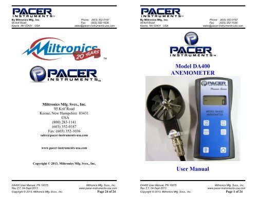
Miltronics 10075-DA400 User Manual Rev 2.7.pdf - Pacer Instruments

Create successful ePaper yourself
Turn your PDF publications into a flip-book with our unique Google optimized e-Paper software.
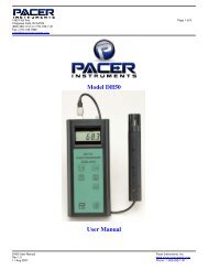
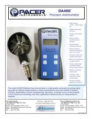
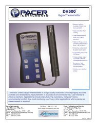
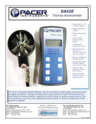
By <strong>Miltronics</strong> Mfg., Inc. Phone: (603) 352-018795 Krif Road Fax: (603) 352-1036Keene, NH 03431 USA sales@pacer-instruments-usa.comBy <strong>Miltronics</strong> Mfg., Inc. Phone: (603) 352-018795 Krif Road Fax: (603) 352-1036Keene, NH 03431 USA sales@pacer-instruments-usa.comSECTION 1 - SPECIFICATIONSRanges:Probe AP275:50 to 7800 ft/min (feet per minute)0.2 to 40.00 m/sec (meters per second)Air Probe AP100: 300 to 6890 ft/min (1.5 to 35.00 m/sec)Accuracy: AP275: ±1.0% of reading ±1 digitAP100: ±0.5% full scale ±0.75% of readingBelow are examples of the formatted output data for <strong>Pacer</strong>’s PremierSeries <strong>Instruments</strong> (units may be different depending on the unitsselected on the LCD display):Model <strong>DA400</strong>:Air,47,FPM Model DA410 displaying in Air Velocity Mode: Air,47,FPM Model DA410 displaying in Volume Flow Mode: Air,251,CFM Model DA420:Air,47,FPM Resolution:1 ft/min or 0.01 m/secModel DA430:Air,47,FPM Operating Temperature:Instrument:32˚ to 125˚F (0˚ to 50˚C)Probes: -4˚ to 212˚F (-20˚ to 100˚C)Model DH500:Power Supply:Battery Life:3 AA alkaline batteriesApprox. 150 hours, without backlightNOTE: Units with USB or RS232 communications, output only Airdata at this time. Temperature & Humidity data is not available onthe output.Battery check: Automatic low battery displayDisplay:0.5” LCD, 4 digits, with LED backlight<strong>DA400</strong> <strong>User</strong> <strong>Manual</strong>, PN <strong>10075</strong> <strong>Miltronics</strong> Mfg. Svcs., Inc.<strong>Rev</strong> 2.7, 04-Sept-2013 www.pacer-instruments-usa.comCopyright © 2013, <strong>Miltronics</strong> Mfg. Svcs., Inc. Page 4 of 24<strong>DA400</strong> <strong>User</strong> <strong>Manual</strong>, PN <strong>10075</strong> <strong>Miltronics</strong> Mfg. Svcs., Inc.<strong>Rev</strong> 2.7, 04-Sept-2013 www.pacer-instruments-usa.comCopyright © 2013, <strong>Miltronics</strong> Mfg. Svcs., Inc. Page 21 of 24
By <strong>Miltronics</strong> Mfg., Inc. Phone: (603) 352-018795 Krif Road Fax: (603) 352-1036Keene, NH 03431 USA sales@pacer-instruments-usa.comBy <strong>Miltronics</strong> Mfg., Inc. Phone: (603) 352-018795 Krif Road Fax: (603) 352-1036Keene, NH 03431 USA sales@pacer-instruments-usa.comClick on File → Properties. You will see the window shown below. Clickon the Settings tab and then click on ASCII Setup… as shown below.AP275 PROBEMake sure that “Append line feeds to incoming line ends” is CHECKEDas shown below. Click OK.AP100 PROBE<strong>DA400</strong> <strong>User</strong> <strong>Manual</strong>, PN <strong>10075</strong> <strong>Miltronics</strong> Mfg. Svcs., Inc.<strong>Rev</strong> 2.7, 04-Sept-2013 www.pacer-instruments-usa.comCopyright © 2013, <strong>Miltronics</strong> Mfg. Svcs., Inc. Page 6 of 24<strong>DA400</strong> <strong>User</strong> <strong>Manual</strong>, PN <strong>10075</strong> <strong>Miltronics</strong> Mfg. Svcs., Inc.<strong>Rev</strong> 2.7, 04-Sept-2013 www.pacer-instruments-usa.comCopyright © 2013, <strong>Miltronics</strong> Mfg. Svcs., Inc. Page 19 of 24
By <strong>Miltronics</strong> Mfg., Inc. Phone: (603) 352-018795 Krif Road Fax: (603) 352-1036Keene, NH 03431 USA sales@pacer-instruments-usa.comPress the SAMPLE RATE key to change the measurement averagingrate (“sample rate”) of the unit: An average value of airspeed measurements during thepreceding 2 seconds is displayed. An average value of airspeed measurements during thepreceding 4 seconds is displayed. An average value of airspeed measurements during thepreceding 8 seconds is displayed. An average value of airspeed measurements during thepreceding 16 seconds is displayed.By <strong>Miltronics</strong> Mfg., Inc. Phone: (603) 352-018795 Krif Road Fax: (603) 352-1036Keene, NH 03431 USA sales@pacer-instruments-usa.comAPPENDIX G – VIEWING AND CAPTURING DATA(IF EQUIPPED WITH EITHER USB OR RS232 OUTPUTS)There are many ways to capture the serial port data from the <strong>Pacer</strong>Instrument. The simplest method is to use a terminal emulator program.Using a terminal emulator allows the serial COM port to be opened, withthe above port settings, and real-time data to be viewed from theinstrument. One such terminal emulator program is WindowsHyperTerminal.To launch Windows HyperTerminal, go to:START → All Programs → Accessories → Communications →HyperTerminalEnter a name for the Connection, such as “<strong>Pacer</strong> <strong>DA400</strong>” and choose anicon.Press the MAX/MIN key to record and display the maximum airspeedreading. The maximum airspeed reading display will alternate with theletter “H” displayed with the sample rate. Press the MAX/MIN keyagain to record an d hold the minimum airspeed reading. The minimum airspeedreading display will alternate with the letter “L” displayed with the sample rate.For example: alternating with signifies that 1065 is the highest airspeedreading since the MAX/MIN key was pressed, and the sample rate is set to 8seconds. alternating with signifies that 82 is the lowest airspeedreading since the MAX/MIN key was pressed, and the sample rate is set to 16seconds.To exit MAX/MIN mode, press the SAMPLE RATE key.Click OK.<strong>DA400</strong> <strong>User</strong> <strong>Manual</strong>, PN <strong>10075</strong> <strong>Miltronics</strong> Mfg. Svcs., Inc.<strong>Rev</strong> 2.7, 04-Sept-2013 www.pacer-instruments-usa.comCopyright © 2013, <strong>Miltronics</strong> Mfg. Svcs., Inc. Page 8 of 24<strong>DA400</strong> <strong>User</strong> <strong>Manual</strong>, PN <strong>10075</strong> <strong>Miltronics</strong> Mfg. Svcs., Inc.<strong>Rev</strong> 2.7, 04-Sept-2013 www.pacer-instruments-usa.comCopyright © 2013, <strong>Miltronics</strong> Mfg. Svcs., Inc. Page 17 of 24
By <strong>Miltronics</strong> Mfg., Inc. Phone: (603) 352-018795 Krif Road Fax: (603) 352-1036Keene, NH 03431 USA sales@pacer-instruments-usa.comBy <strong>Miltronics</strong> Mfg., Inc. Phone: (603) 352-018795 Krif Road Fax: (603) 352-1036Keene, NH 03431 USA sales@pacer-instruments-usa.comAPPENDIX B – BATTERY REPLACEMENTYou are now ready to capture the data being measured byyour instrument.Please refer to Appendix G – Viewing and Capturing Datafor further instructions.<strong>DA400</strong> <strong>User</strong> <strong>Manual</strong>, PN <strong>10075</strong> <strong>Miltronics</strong> Mfg. Svcs., Inc.<strong>Rev</strong> 2.7, 04-Sept-2013 www.pacer-instruments-usa.comCopyright © 2013, <strong>Miltronics</strong> Mfg. Svcs., Inc. Page 10 of 24<strong>DA400</strong> <strong>User</strong> <strong>Manual</strong>, PN <strong>10075</strong> <strong>Miltronics</strong> Mfg. Svcs., Inc.<strong>Rev</strong> 2.7, 04-Sept-2013 www.pacer-instruments-usa.comCopyright © 2013, <strong>Miltronics</strong> Mfg. Svcs., Inc. Page 15 of 24
By <strong>Miltronics</strong> Mfg., Inc. Phone: (603) 352-018795 Krif Road Fax: (603) 352-1036Keene, NH 03431 USA sales@pacer-instruments-usa.comBy <strong>Miltronics</strong> Mfg., Inc. Phone: (603) 352-018795 Krif Road Fax: (603) 352-1036Keene, NH 03431 USA sales@pacer-instruments-usa.comAPPENDIX D – ANALOG OUTPUTS (IF EQUIPPED)If the instrument is equipped with the analog output option, there will be a fivepinconnector on the bottom of the instrument. Also, an analog output cable willbe included with the instrument. This cable will have a five-pin connector onone end and four tinned wires on the other end.The instrument will output a Voltage between 0 and 5 Volts that corresponds tothe Air Velocity measured by the instrument. The output range, pinassignments, and wire colors are given in the table below. Also shown is ablock diagram of the analog output circuit.Analog Output circuit block diagram and connector pin assignmentCorrespondingWire Analog Output Measurement Equation* to convert fromColor Pin # Function Voltage Range Range Volts (V) to Measurement ValueBLK 1 Ground --- N/A --- --- N/A --- --- N/A ---GRN 2 Air Velocity 0 to 5 Volts 0 to 10,000 FPM Air Velocity = 2000×VGRY 3 --- Not Used --- --- N/A --- --- N/A --- --- N/A ---WHT 4 --- Not Used --- --- N/A --- --- N/A --- --- N/A ---*To convert from Volts to Air Velocity in Feet per Minute, multiply by 2000.► For example, an analog output of 2.375 Volts means that the instrument ismeasuring an air velocity of 4750 feet per minute (FPM).► 2.375 Volts × 2000 = 4750 FPMMating Cable Connector:Binder Part No. 99-0413-00-05Note: When using analog outputs, there is an additional ±1% error in theanalog output voltage. This is in addition to the normal measurement error.► For example, an air velocity reading of 500 FPM would normally have anaccuracy of ±1% of reading ±1 digit (±6 FPM) when the data is viewedon the LCD display.► With the additional error associated with the analog output voltage, theeffective accuracy of the analog output for this air velocity measurementwill be ±2% of reading ±1 digit (±11 FPM).Custom Analog Voltage Outputs are also available – contact <strong>Pacer</strong> for details.<strong>DA400</strong> <strong>User</strong> <strong>Manual</strong>, PN <strong>10075</strong> <strong>Miltronics</strong> Mfg. Svcs., Inc.<strong>Rev</strong> 2.7, 04-Sept-2013 www.pacer-instruments-usa.comCopyright © 2013, <strong>Miltronics</strong> Mfg. Svcs., Inc. Page 12 of 24<strong>DA400</strong> <strong>User</strong> <strong>Manual</strong>, PN <strong>10075</strong> <strong>Miltronics</strong> Mfg. Svcs., Inc.<strong>Rev</strong> 2.7, 04-Sept-2013 www.pacer-instruments-usa.comCopyright © 2013, <strong>Miltronics</strong> Mfg. Svcs., Inc. Page 13 of 24